Nibe PCS 44 User guide

LEK
LEK
LEK
PCS 44
Installatörshandbok Passiv kyla
för NIBE F1145, F1245
SE
Installer manual Passive cooling
for NIBE F1145, F1245
GB
Installateurhandbuch Passive Kühlung
für NIBE F1145, F1245
DE
Asentajan käsikirja Passiivinen jäähdytys
NIBE F1145, F1245
FI
IHB 1301-1
231409


Allmänt
Detta tillbehör används då NIBE F1145/F1245 installeras
i en anläggning med frikyla.
Innehåll
Pump1st
Pumpisolering1st
Avstängningsventil2st
Backventil1st
Shuntventil med ställdon1st
Temperaturgivare2st
Isoleringstejp1st
Buntband4st
Utbytespackning2st
Värmeledningspasta2st
Aluminiumtejp1st
Kit för tillbehörskort1st
Tekniska data
PCS44
DN25Dimension på shuntventilen
9 (0,09)kPa
(bar)
Tryckfall vid 2,0 l/s
11KV-värde på shuntventilen
1 1/4'' G32Dimension på backventilen
Ø15mmDimension på avstängningsventilen
inlopp
Ø22mmDimension på avstängningsventilen
utlopp
Komponentplacering
LEK
AA5-X4
AA5-S2
AA5-X2 AA5-X9 X1
FA1
AA5-F1AA5
Elkomponenter
Automatsäkring, 10AFA1
Anslutningsplint, spänningsmatningX1
TillbehörskortAA5
Anslutningsplint, givare och extern blocke-
ring
AA5-X2
Anslutningsplint, kommunikationAA5-X4
Anslutningsplint, cirkulationspump, shunt
och hjälprelä
AA5-X9
DIP-switchAA5-S2
Finsäkring, T4AH250VAA5-F1
Beteckningar i komponentplacering enligt standard IEC
81346-1 och 81346-2.
3
Svenska, Installatörshandbok - PCS 44
SE

Röranslutning
Allmänt
För att undvika kondensbildning måste rörledningar och
övriga kalla ytor isoleras med diffusionstätt material. Vid
stort kylbehov krävs fläktkonvektor med droppskål och
avloppsanslutning.
Köldbärarkretsen skall förses med tryckexpansionskärl.
Eventuellt befintligt nivåkärl byts ut.
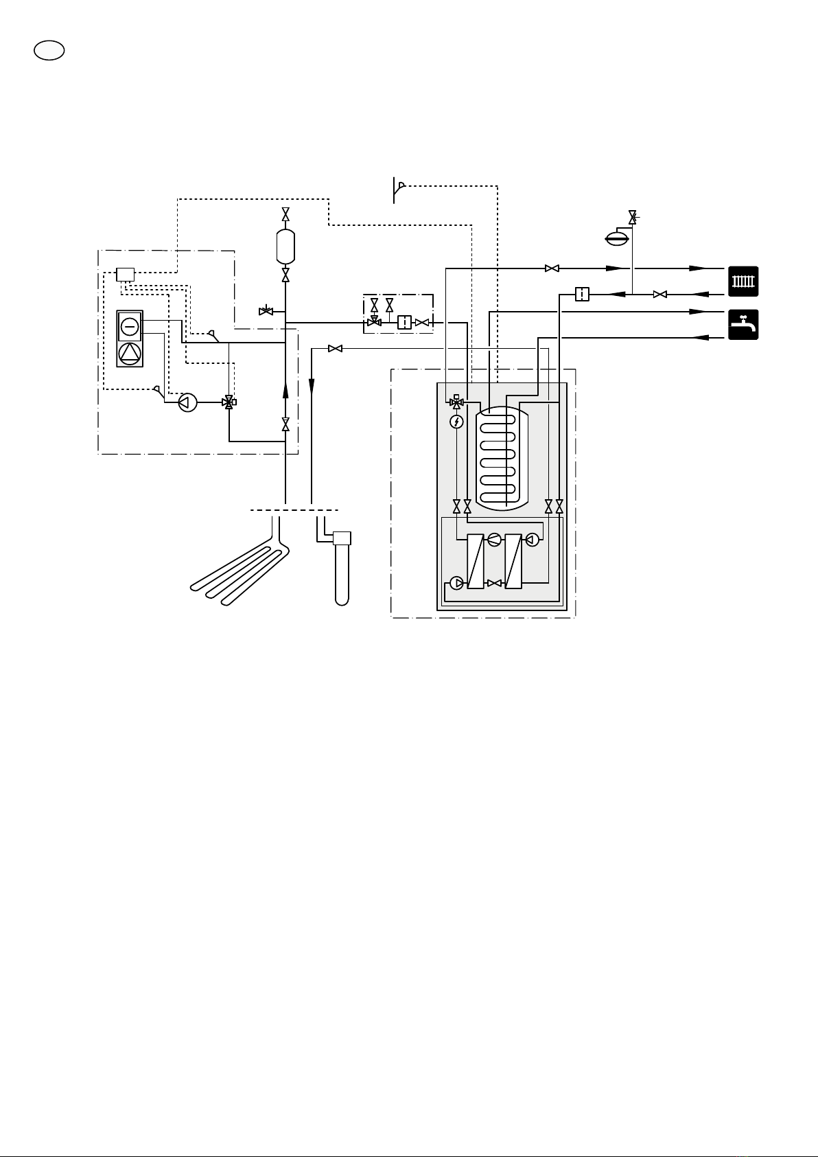
Backventil, shuntventil och cirkulationspump
႑Montera den bipackade backventilen mellan de två T-
rörsanslutningarna till PCS 44 närmast värmepumpen
på köldbärare in (se principschema).
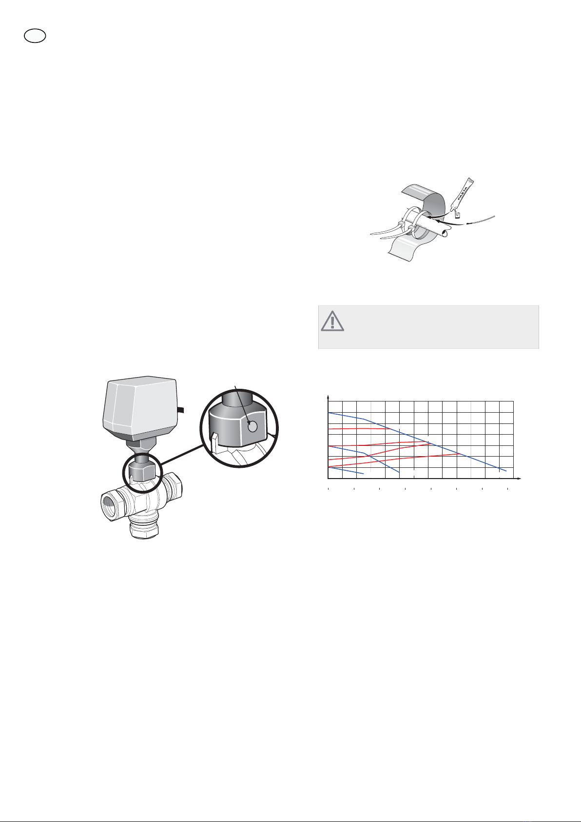
႑Montera shuntventilen (QN18) på framledningen till
fläktkonvektorn (port 1) så att port 1 är öppen mot
port 2 (blå färgmarkering) när motorn är i viloläge. Vid
signal öppnar port 1 mot port 3 (röd färgmarkering).
Returledningen från fläktkonvektorn kopplas till
shuntventilen (port 2) samt köldbärare in närmast vär-
mepumpen.
႑Den extra cirkulationspumpen (GP13) monteras efter
shuntventilen (QN18) på framledningen till fläktkonvek-
torn.
LEK
Färgmarkering
1
2
3
Temperaturgivare
႑Framledningsgivaren för kylsystemet (BT64) monteras
på röret efter cirkulationspumpen (GP13) i flödesrikt-
ningen.
႑Returledningsgivaren för kylsystemet (BT65) monteras
på röret från kylsystemet.
K
Temperaturgivarna monteras med buntband tillsammans
med värmeledningspasta och aluminiumtejp. Därefter
skall de isoleras med medföljande isolertejp.
OBS!
Givar- och kommunikationskablar får ej förläggas
i närheten av starkströmsledning.
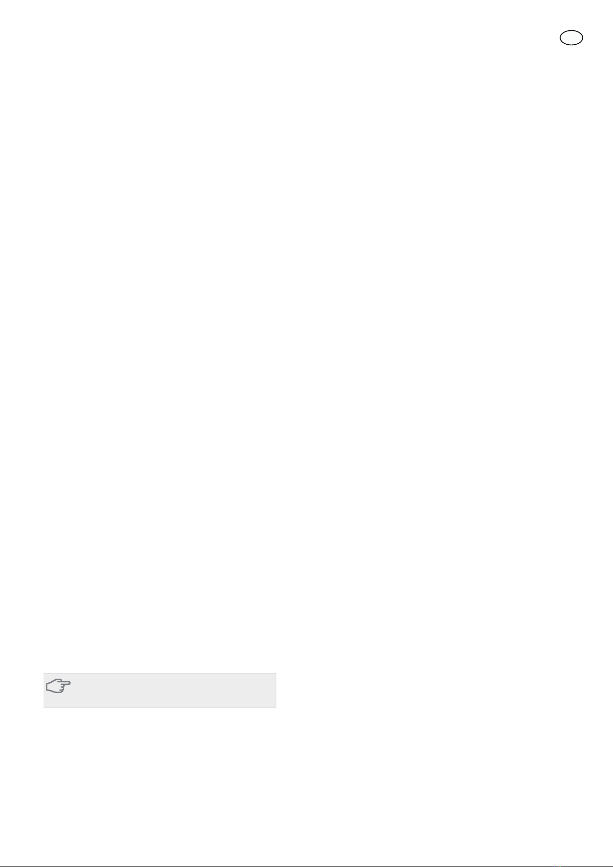
Pump- och tryckfallsdiagram
0 200 400 600 800 1000 1200 1400 1600 1800 2000 2200 2400 2600
0
10
20
30
40
50
60
70
Tillgängligt tryck
kPa
Flöde
l/h
l/s
0,40,30,20,10 0,5 0,6 0,7
Speed I
PP1
CP1PP2
Speed II Speed III
CP2
Tillgängligt tryck
kPa
Flöde
Välj mellan sju inställningar på pumpen. Du kan välja
mellan tre olika konstanta hastigheter (I, II eller III) alter-
nativt två olika proportionella (PP) respektive konstanta
tryckkurvor (CP) där 1 är lägsta och 2 högsta.
4
SE

Principschema
Förklaring
VärmepumpsystemEB100
Temperaturgivare, utomhusBT1
Temperaturgivare, varmvattenBT6
VärmepumpEB100
SmutsfilterHQ1
KylsystemEQ1
Apparatlåda med tillbehörskort (AA5)AA25
Framledningsgivare, kylaBT64
Returledningsgivare, kylaBT65
FläktkonvektorEP13
Cirkulationspump, kylaGP13
Shuntventil, kylaQN18
BackventilRM5
Övrigt
Expansionskärl, värmebärarsidaCM1
NivåkärlCM2
AckumulatortankCP10
Bergvärme/JordkollektorEP12
Säkerhetsventil, värmebärareFL2
Säkerhetsventil, köldbärareFL3
Påfyllningsventil, köldbärareQM12
Avstängningsventil, värmebärare framQM31
Avstängningsventil, värmebärare returQM32
Avstängningsventil, köldbärare framQM34
AvstängningsventilQM42
Påfyllnadsventilsats, köldbärareXL15
Beteckningar i komponentplacering enligt standard IEC 81346-1 och 81346-2.
Principschema F1145 med PCS 44
-FL3
-QM42
-QM12
-CM2
-QM34
-HQ1
-CP10
-XL15
-EB100-BT1
-EB100-BT6
-EB100
-QM31
-QM32
-FL2
-CM1
-RM5
-EP13
-QN18
-GP13
-BT64
-BT65
-AA25
1
2
3
-EB100
-EQ1
-EP12
5
SE

Principschema F1245 med PCS 44
-FL3
-QM42
-QM12
-CM2
-QM34
-XL15
-EB100-BT1
-EB100
-EB100-HQ1
-QM31
-QM32
-RM5
-EP13
-QN18
1
2
3
-GP13
-BT64
-BT65
-AA25
-EQ1
-EB100
-FL2
-CM1
-EP12
6
SE

Elinkoppling
OBS!
All elektrisk inkoppling skall ske av behörig
elektriker.
Elektrisk installation och ledningsdragning skall
utföras enligt gällande bestämmelser.
Värmepumpen ska vara spänningslös vid instal-
lation av PCS 44.
Elschema finns i slutet av denna installatörshandbok.
Anslutning av kommunikation
Detta tillbehör innehåller ett tillbehörskort (AA5) som ska
anslutas direkt till värmepumpen på ingångskortet (plint
AA3-X4).
Om flera tillbehör ska anslutas eller redan finns installera-
de måste nedanstående instruktion följas.
Det första tillbehörskortet ska anslutas direkt till värme-
pumpens plint AA3-X4. De efterföljande korten ansluts
i serie med föregående kort.
Använd kabeltyp LiYY, EKKX eller likvärdig.
1
2
3
4
5
6
7
8
AA5-X4
15
A
B
GND
A
B
GND
A
B
GND
A
B
GND
A
B
GND
14
13
AA3-X4
1
2
3
4
5
6
7
8
AA5-X4
)
)
$$;
7LOOEHK¸UVNRUW
7LOOEHK¸UVNRUW
ON
12345678
-X9
-X2
24 20212223 1516171819 1011121314 567891
1
N
L
PE
PE
1
2
3
4
5
6
7
8
2
3
4
5
6
7
8
9
234
-X8
-X4
-X10
-X1
$$;
ON
12345678
-X9
-X2
24 20212223 1516171819 1011121314 567891
1
N
L
PE
PE
1
2
3
4
5
6
7
8
2
3
4
5
6
7
8
9
234
-X8
-X4
-X10
-X1
$$;
$$;
(%
Anslutning av matning
Anslut spänningsmatningen till plint X1 enligt bild.
3
2
1N
230V 50Hz-X1
L
PE
$SSDUDWO§GD ([WHUQW
7
SE

ON
12345678
-X9
-X2
24 20212223 1516171819 1011121314 567891
1
N
L
PE
PE
1
2
3
4
5
6
7
8
2
3
4
5
6
7
8
9
234
-X8
-X4
-X10
-X1
$$; $$;$$6
Anslutning av givare
Använd kabeltyp LiYY, EKKX eller likvärdig.
Framledningsgivare, kyla (BT64)
Anslut framledningsgivaren till AA5-X2:21-22.
Returledningsgivare, kyla (BT65)
Anslut returledningsgivaren till AA5-X2:19-20.
Extern blockering
En kontakt (NO) kan anslutas till AA5-X2:23-24 för att
kunna blockera kyldriften. När kontakten sluts blockeras
kyldriften.
24 20212223 1516171819 1314
$$;
%7
([WHUQW
$SSDUDWO§GD
([WHUQ EORFNHULQJ
%7
TÄNK PÅ!
Reläutgångarna på tillbehörskortet får max be-
lastas med 2 A (230 V) totalt.
Anslutning av cirkulationspump (GP13)
Anslut cirkulationspumpen (GP13) till AA5-X9:2 (230 V),
AA5-X9:1 (N) och X1:3 (PE).
1
2
3
4
L
N
PE
3
2
1
$SSDUDWO§GD ([WHUQW
*3
$$;
;
Anslutning av shuntmotor (QN18)
Anslut shuntmotorn (QN18) till AA5-X9:6 (230 V, öppna),
AA5-X9:5 (N) och AA5-X9:4 (230 V, stäng).
1
2
3
4
5
6
7
8
9
3
2
1
5¸G
%O§
6YDUW
SSQD
6W¦QJ
*XO*U¸Q 41
$SSDUDWO§GD ([WHUQW
$$;
;
1
DIP-switch
DIP-switchen på tillbehörskortet ska ställas in enligt ne-
dan.
ON
12345678
ON
12345678
-X9
-X2
24 20212223 1516171819 1011121314 567891
1
N
L
PE
PE
1
2
3
4
5
6
7
8
2
3
4
5
6
7
8
9
234
-X8
-X4
-X10
-X1
AA5-S2
Reläutgång för kyllägesindikering
Möjlighet finns till extern indikering av kyllägesindikering
genom reläfunktion via ett potentialfritt växlande relä
(max 2 A) på ingångskortet (AA3), plint X7.
Ansluts kyllägesindikering till plint X7 måste det väljas i
meny 5.4.
Programinställningar
Programinställningen av PCS 44 kan göras via startguiden
eller direkt i menysystemet.
8
SE

Startguiden
Startguiden visas vid första uppstart efter värmepumpsin-
stallationen, men finns även i meny 5.7.
Menysystemet
Om du inte gör alla inställningar via startguiden eller be-
höver ändra någon inställning kan du göra detta i meny-
systemet.
Meny 5.2 - systeminställningar
Aktivering/avaktivering av tillbehör.
Välj: "passiv kyla 4-rör"
Meny 1.1 - temperatur
Inställning av inomhustemperatur (kräver rumstempera-
turgivare).
Meny 1.9.5 - kylinställningar
Här kan du exempelvis göra följande inställningar:
႑Lägsta framledningstemperatur vid kyla.
႑Önskad framledningstemperatur vid utomhustempera-
turen +20 och +40 °C.
႑Tid mellan kyla och värmedrift eller tvärt om.
႑Val om rumsgivare ska styra kylan.
႑Hur mycket rumstemperaturen får sjunka respektive
öka jämfört med önskad temperatur innan övergång
till värme respektive kyldrift (kräver rumsgivare).
႑Diverse shuntinställningar.
Meny 4.9.2 - autolägesinställning
Om värmepumpens driftläge är satt till "auto" väljer den
själv, beroende på medelutetemperatur, när start och
stopp av tillsats samt värmeproduktion respektive kyldrift
ska tillåtas.
I denna meny väljer du dessa medelutetemperaturer.
Du kan även ställa in under hur lång tid (filtreringstid)
medeltemperaturen räknas. Väljer du 0 innebär det att
aktuell utetemperatur används.
Meny 5.6 - tvångsstyrning
Tvångsstyrning av de olika komponenterna i värmepum-
pen samt i de olika tillbehören som eventuellt är anslutna.
EQ1-AA5-K1: Aktivering av cirkulationspump (GP13).
EQ1-AA5-K2: Signal (stäng) till shunt (QN18).
EQ1-AA5-K3: Signal (öppna) till shunt (QN18).
EQ1-AA5-K4: Ingen funktion.
TÄNK PÅ!
Se även Installatörshandboken för F1145/F1245.
9
SE

General
This accessory is used when NIBE F1145/F1245 is installed
in an installation with passive cooling.
Contents
Pump1x
Pump insulation1x
Shut-off valve2x
Non-return valve1x
Shunt valve with actuator1x
Temperature sensor2x
Insulation tape1x
Cable ties4x
Replacement gasket2x
Heating pipe paste2x
Aluminium tape1x
Kit for accessory card1x
Technical specifications
PCS44
DN25Dimension of shunt valve
9 (0,09)kPa
(bar)
Pressure drop at 2,0 l/s
11KV value on shunt valve
1 1/4'' G32Dimension of non-return valve
Ø15mmDimension of the shut-off valve inlet
Ø22mmDimension of the shut-off valve outlet
Component positions
LEK
AA5-X4
AA5-S2
AA5-X2 AA5-X9 X1
FA1
AA5-F1AA5
Electrical components
Miniature circuit-breaker. 10AFA1
Terminal block, power supplyX1
Accessory cardAA5
Terminal block, sensors and external
blocking
AA5-X2
Terminal block, communicationAA5-X4
Terminal block, circulation pump, mixing
valve and auxiliary relay
AA5-X9
DIP switchAA5-S2
Fine wire fuse, T4AH250VAA5-F1
Designations in component locations according to
standard IEC 81346-1 and 81346-2.
10
English, Installer manual - PCS 44
GB

Pipe connections
General
Pipes and other cold surfaces must be insulated with dif-
fusion-proof material to prevent condensation. Where
the cooling demand is high, fan convectors with drip trays
and drain connection are needed.
The brine circuit must be supplied with a pressure expan-
sion vessel. If there is already a level vessel installed this
should be replaced.
Check valve, mixing valve and circulation
pump
႑Install the supplied check valve between two T-pipe
connections to PCS 44 nearest the heat pump on brine
in (see the outline diagram).
႑Install the mixing valve (QN18) on the flow line to the
fan convector (port 1) so that port 1 is open towards
port 2 (blue coloured) when the motor is in idle mode.
In the event of a signal, port 1 opens towards port 3
(red coloured). The return line from the fan convector
is connected to the mixing valve (port 2) as well as brine
in closest to the heat pump.
႑Install the extra circulation pump (GP13) after the mix-
ing valve (QN18) on the flow line to the fan convector.
LEK
Colour marking
1
2
3
Temperature sensor
႑Install the flow temperature sensor for the cooling sys-
tem (BT64) on the pipe after the circulation pump
(GP13) in the direction of flow.
႑Install the return line sensor for the cooling system
(BT65) on the pipe from the cooling system.
K
Install the temperature sensors with cable ties with the
heat conducting paste and aluminium tape. Then insulate
with supplied insulation tape.
NOTE
Sensor and communication cables must not be
placed near power cables.
Pump and pressure drop diagrams
0 200 400 600 800 1000 1200 1400 1600 1800 2000 2200 2400 2600
0
10
20
30
40
50
60
70
Tillgängligt tryck
kPa
Flöde
l/h
l/s
0,40,30,20,10 0,5 0,6 0,7
Speed I
PP1
CP1PP2
Speed II Speed III
CP2
Available pressure
kPa
Flow
Choose between seven settings on the pump. You can
choose between three different constant speeds (I, II or
III) or two different curve types, one proportional pressure
(PP) and one constant pressure (CP), where 1 is lowest
and 2 highest.
11
GB

Outline diagram
Explanation
Heat pump systemEB100
Temperature sensor, outdoorBT1
Temperature sensor, hot waterBT6
Heat pumpEB100
Particle filterHQ1
Cooling systemEQ1
Unit box with accessory card (AA5)AA25
Flow temperature sensor, coolingBT64
Return line sensor, coolingBT65
Fan convectorsEP13
Circulation pump, coolingGP13
Mixing valve, coolingQN18
Non-return valveRM5
Miscella-
neous
Expansion vessel, heating medium sideCM1
Level vesselCM2
Accumulator tankCP10
Ground-source heating/Ground collectorEP12
Safety valve, heating mediumFL2
Safety valve, brineFL3
Filler valve, brineQM12
Shut-off valve, heating medium flowQM31
Shut off valve, heating medium returnQM32
Shut off valve, brine flowQM34
Shut-off valveQM42
Filling set, brineXL15
Designations in component locations according to standard IEC 81346-1 and 81346-2.
Outline diagram F1145 with PCS 44
-FL3
-QM42
-QM12
-CM2
-QM34
-HQ1
-CP10
-XL15
-EB100-BT1
-EB100-BT6
-EB100
-QM31
-QM32
-FL2
-CM1
-RM5
-EP13
-QN18
-GP13
-BT64
-BT65
-AA25
1
2
3
-EB100
-EQ1
-EP12
12
GB

Outline diagram F1245 with PCS 44
-FL3
-QM42
-QM12
-CM2
-QM34
-XL15
-EB100-BT1
-EB100
-EB100-HQ1
-QM31
-QM32
-RM5
-EP13
-QN18
1
2
3
-GP13
-BT64
-BT65
-AA25
-EQ1
-EB100
-FL2
-CM1
-EP12
13
GB

Electrical connection
NOTE
All electrical connections must be carried out by
an authorised electrician.
Electrical installation and wiring must be carried
out in accordance with the stipulations in force.
The heat pump must not be powered when in-
stalling PCS 44.
The electrical circuit diagram is at the end of this Installer
handbook.
Connecting communication
This accessory contains an accessories card (AA5) that
must be connected directly to the heat pump on the input
card (terminal block AA3-X4).
If several accessories are to be connected or are already
installed, the following instructions must be followed.
The first accessory card must be connected directly to the
heat pump's terminal block AA3-X4. The following cards
must be connected in series with the previous card.
Use cable type LiYY, EKKX or similar.
1
2
3
4
5
6
7
8
AA5-X4
15
A
B
GND
A
B
GND
A
B
GND
A
B
GND
A
B
GND
14
13
AA3-X4
1
2
3
4
5
6
7
8
AA5-X4
)
)
$$;
$FFHVVRU\ FDUG
$FFHVVRU\ FDUG
ON
12345678
-X9
-X2
24 20212223 1516171819 1011121314 567891
1
N
L
PE
PE
1
2
3
4
5
6
7
8
2
3
4
5
6
7
8
9
234
-X8
-X4
-X10
-X1
$$;
ON
12345678
-X9
-X2
24 20212223 1516171819 1011121314 567891
1
N
L
PE
PE
1
2
3
4
5
6
7
8
2
3
4
5
6
7
8
9
234
-X8
-X4
-X10
-X1
$$;
$$;
(%
Connecting the supply
Connect the power supply to terminal block X1 as illus-
trated.
3
2
1N
230V 50Hz-X1
L
PE
8QLW ER[ ([WHUQDO
14
GB

ON
12345678
-X9
-X2
24 20212223 1516171819 1011121314 567891
1
N
L
PE
PE
1
2
3
4
5
6
7
8
2
3
4
5
6
7
8
9
234
-X8
-X4
-X10
-X1
$$; $$;$$6
Connecting sensors
Use cable type LiYY, EKKX or similar.
Flow temperature sensor, cooling (BT64)
Connect the flow temperature sensor to AA5-X2:21-22.
Return line sensor, cooling (BT65)
Connect the return line sensor to AA5-X2:19-20.
External blocking
A contact (NO) can be connected to AA5-X2:23-24 to
block cooling operation. When the contact closes, cooling
operation is blocked.
24 20212223 1516171819 1314
$$;
%7
([WHUQDO
8QLW ER[
([WHUQDO EORFNLQJ
%7
Caution
The relay outputs on the accessory card can have
a max load of 2 A (230 V) in total.
Connection of the circulation pump (GP13)
Connect the circulation pump (GP13) to AA5-X9:2 (230
V), AA5-X9:1 (N) and X1:3 (PE).
1
2
3
4
L
N
PE
3
2
1
8QLW ER[ ([WHUQDO
*3
$$;
;
Connection of the mixing valve motor (QN18)
Connect the mixing valve motor (QN18) to AA5-X9:6
(230 V, open), AA5-X9:5 (N) and AA5-X9:4 (230 V, close).
1
2
3
4
5
6
7
8
9
3
2
1
5HG
%OXH
%ODFN
2SHQ
&ORVH
<HOORZ*UHHQ 41
8QLW ER[ ([WHUQDO
$$;
;
1
DIP switch
The DIP switch on the accessory card must be set as fol-
lows.
ON
12345678
ON
12345678
-X9
-X2
24 20212223 1516171819 1011121314 567891
1
N
L
PE
PE
1
2
3
4
5
6
7
8
2
3
4
5
6
7
8
9
234
-X8
-X4
-X10
-X1
AA5-S2
Relay output for cooling mode indication
It is possible to have an external indication of the cooling
mode through relay function via a potential free variable
relay (max 2 A) on the input circuit board (AA3), terminal
block X7.
If cooling mode indication is connected to terminal block
X7 it must be selected in menu 5.4, see
Program settings
Program setting of PCS 44 can be performed via the start
guide or directly in the menu system.
15
GB

Start guide
The start guide appears upon first start-up after heat
pump installation, but is also found in menu 5.7.
Menu system
If you do not make all settings via the start guide or need
to change any of the settings, this can be done in the
menu system.
Menu 5.2 - system settings
Activating/deactivating of accessories.
Select: "passive cooling 4-pipe"
Menu 1.1 - temperature
Setting indoor temperature (room temperature sensor is
required).
Menu 1.9.5 - cooling settings
Here you can perform the following settings:
႑Lowest flow line temperature when cooling.
႑Desired flow temperature at an outdoor air temperature
of +20 and +40 °C.
႑Time between cooling and heating or vice versa.
႑Selection of room sensor can control cooling.
႑How much the room temperature may decrease or in-
crease compared to the desired temperature before
switching to heating respectively cooling (requires room
sensor).
႑Misc. shunt settings.
Menu 4.9.2 - auto mode setting
When heat pump operating mode is set to "auto“ it se-
lects when start and stop of additional heat, heat produc-
tion and cooling is permitted, dependent on the average
outdoor temperature.
Select the average outdoor temperatures in this menu.
You can also set the time over which (filtering time) the
average temperature is calculated. If you select 0, the
present outdoor temperature is used.
Menu 5.6 - forced control
Forced control of the different components in the heat
pump as well as in the different accessories that may be
connected.
EQ1-AA5-K1: Activating the circulation pump (GP13).
EQ1-AA5-K2: Signal (close) to mixing valve (QN18).
EQ1-AA5-K3: Signal (open) to mixing valve (QN18).
EQ1-AA5-K4: No function.
Caution
Also see the Installer manual for F1145/F1245.
16
GB

Allgemeines
Dieses Zubehör wird benötigt, wenn NIBE F1145/F1245
in einer Anlage mit passiver Kühlung installiert wird.
Inhalt
Pumpe1 St.
Isolierkappe Umwälzpumpe1 St.
Absperrventil2 St.
Rückschlagventil1 St.
Mischventil mit Stellvorrichtung1 St.
Fühler2 St.
Isolierband1 St.
Kabelbinder4 St.
Dichtung2 St.
Wärmeleitpaste2 St.
Aluminiumklebeband1 St.
Satz für Zusatzplatine1 St.
Technische Daten
PCS44
DN25Abmessung Mischventil
9 (0,09)kPa
(Bar)
Druckverlust bei 2,0 l/s
11KV-Wert des Mischventils
1 1/4'' G32Größe des Rückschlagventils
Ø15mmEinlassgröße des Absperrventils
Ø22mmAuslassgröße des Absperrventils
Position der Komponenten
LEK
AA5-X4
AA5-S2
AA5-X2 AA5-X9 X1
FA1
AA5-F1AA5
Elektrische Komponenten
Sicherungsautomat, 10 AFA1
Anschlussklemme, SpannungsversorgungX1
ZubehörplatineAA5
Anschlussklemme für Fühler und extern
geschaltete Blockierung
AA5-X2
Anschlussklemme für Kommunikationslei-
tung
AA5-X4
Anschlussklemme für Umwälzpumpe,
Mischventil und Hilfsrelais
AA5-X9
DIP-SchalterAA5-S2
Feinsicherung, T4AH250VAA5-F1
Bezeichnungen der Komponentenpositionen gemäß
Standard IEC 81346-1 und 81346-2.
17
Deutsch, Installateurhandbuch - PCS 44
DE

Rohranschluss/Durchflussmes-
ser
Allgemeines
Um eine Kondensatbildung zu vermeiden, müssen Rohr-
leitungen und andere kalte Oberflächen mit diffusions-
dichtem Material isoliert werden. Liegt ein hoher Kühlbe-
darf vor, sind Gebläsekonvektoren mit Tropfschale und
Kondensatanschluss erforderlich.
Der Kälteträgerkreis ist mit einem Druckausdehnungsge-
fäß auszustatten. Ein eventuell vorhandenes Niveaugefäß
ist im Zuge der Installationsarbeiten zur ersetzen.
Rückschlagventil, Mischventil und Umwälz-
pumpe
႑Montieren Sie das beiliegende Rückschlagventil zwi-
schen den beiden T-Rohranschlüssen für PCS 44 an der
Wärmepumpe am Wärmequelleneingang (siehe Prin-
zipskizze).
႑Montieren Sie das Mischventil (QN18) am Vorlauf zum
Gebläsekonvektor (Anschluss 1), sodass Anschluss 1
zu Anschluss 2 (blaue Farbkennzeichnung) geöffnet
ist, wenn sich der Motor im Ruhezustand befindet. Bei
einem Signal öffnet sich Anschluss 1 zu Anschluss 3
(rote Farbkennzeichnung). Der Rücklauf vom Gebläse-
konvektor wird mit dem Mischventil (Anschluss 2) sowie
dem Wärmequelleneingang an der Wärmepumpe ver-
bunden.
႑Die zusätzliche Umwälzpumpe (GP13) wird nach dem
Mischventil (QN18) am Vorlauf zum Gebläsekonvektor
angebracht.
LEK
Farbkennzeichnung
1
2
3
Fühler
႑Der Vorlauffühler für das Kühlsystem (BT64) wird am
Rohr nach der Umwälzpumpe (GP13) in Strömungsrich-
tung montiert.
႑Der Rücklauffühler für das Kühlsystem (BT65) wird am
Rohr vom Kühlsystem montiert.
K
Die Fühler werden mit Kabelbinder, Wärmeleitpaste und
Aluminiumband angebracht. Anschließend sind sie mit
dem beiliegenden Isolierband zu umwickeln.
HINWEIS!
Fühler- und Kommunikationskabel dürfen nicht
in der Nähe von Starkstromleitungen verlegt
werden.
Pumpenkennliniendiagramm
0 200 400 600 800 1000 1200 1400 1600 1800 2000 2200 2400 2600
0
10
20
30
40
50
60
70
Tillgängligt tryck
kPa
Flöde
l/h
l/s
0,40,30,20,10 0,5 0,6 0,7
Speed I
PP1
CP1PP2
Speed II Speed III
CP2
Verfügbarer Druck
kPa
Fluss
Es stehen sieben Pumpeneinstellungen zur Auswahl. Sie
können zwischen drei verschiedenen konstanten Drehzah-
len (I, II oder III) bzw. zwei unterschiedlichen proportiona-
len (PP) oder konstanten Druckkurven (CP) wählen, wobei
1 die niedrigste und 2 die höchste Einstellung ist.
18
DE

Prinzipskizze
Erklärung
WärmepumpensystemEB100
AußentemperaturfühlerBT1
Fühler, BrauchwasserBT6
WärmepumpeEB100
SchmutzfilterHQ1
KühlsystemEQ1
Gerätegehäuse mit Zubehörplatine (AA5)AA25
Vorlauffühler, KühlungBT64
Rücklauffühler, KühlungBT65
KälteverbraucherEP13
Umwälzpumpe, KühlungGP13
Mischventil, KühlungQN18
RückschlagventilRM5
Sonsti-
ges
Ausdehnungsgefäß, HeizungsseiteCM1
NiveaugefäßCM2
SpeichertankCP10
Felswärme/ErdkollektorEP12
Sicherheitsventil, HeizungsmediumFL2
Sicherheitsventil, WärmequellenmediumFL3
Einfüllventil, WärmequellenmediumQM12
Absperrventil, HeizungsvorlaufQM31
Absperrventil, HeizungsrücklaufQM32
Absperrventil, WärmequellenmediumvorlaufQM34
AbsperrventilQM42
Einfüllventilset, WärmequellenmediumXL15
Bezeichnungen der Komponentenpositionen gemäß Standard IEC 81346-1 und 81346-2.
Prinzipskizze F1145 mit PCS 44
-FL3
-QM42
-QM12
-CM2
-QM34
-HQ1
-CP10
-XL15
-EB100-BT1
-EB100-BT6
-EB100
-QM31
-QM32
-FL2
-CM1
-RM5
-EP13
-QN18
-GP13
-BT64
-BT65
-AA25
1
2
3
-EB100
-EQ1
-EP12
19
DE

Prinzipskizze F1245 mit PCS 44
-FL3
-QM42
-QM12
-CM2
-QM34
-XL15
-EB100-BT1
-EB100
-EB100-HQ1
-QM31
-QM32
-RM5
-EP13
-QN18
1
2
3
-GP13
-BT64
-BT65
-AA25
-EQ1
-EB100
-FL2
-CM1
-EP12
20
DE
Other manuals for PCS 44
4
Table of contents
Languages:
Other Nibe Freezer manuals
Popular Freezer manuals by other brands

Electrolux
Electrolux EUCP2245AW user manual

Electrolux
Electrolux SG245N10 user manual

Electrolux
Electrolux ERB 2522 Instruction booklet

Signature
Signature SCA2602A+XNF Instructions for use

Russell Hobbs
Russell Hobbs RHCF60 instruction manual

Nostalgia Electrics
Nostalgia Electrics Retro BPC700 instruction manual