Nice TTDRGB Technical specifications

TTDRGB
LED control range
EN - Instructions and warnings for installation and use

2 – ENGLISH
ENGLISH
Translation of the original instructions in full
CONTENTS
GENERAL SAFETY WARNINGS AND
PRECAUTIONS
1
1 GENERALSAFETYWARNINGSANDPRECAUTIONS
a
WARNING! Important safety instructions. Observe all the
instructions as improper installation may cause serious
damages.
a
WARNING! Important safety instructions. It is important
to comply with these instructions to ensure personal
safety. Store these instructions carefully.
a
According to the latest European legislation, an automat-
ed device must be constructed in conformity to the har-
monised rules specied in the current Machinery Direc-
tive, which allow for declaring the presumed conformity
of the automation. Consequently, all the operations for
connecting the product to the mains electricity, its com-
missioning and maintenance must be carried out exclu-
sively by a qualied and expert technician.
a
In order to avoid any danger from inadvertent resetting
of the thermal cut-off device, this appliance must not be
powered through an external switching device, such as a
timer, or connected to a supply that is regularly powered
or switched off by the circuit.
WARNING! Please abide by the following warnings:
–Before commencing the installation, check the “Product techni-
cal specications”, in particular whether this product is suitable
for automating your guided part. Should it not be suitable, do
NOT proceed with the installation.
–The product cannot be used before it has been commissioned
as specied in the “Testing and commissioning” chapter.
–Before proceeding with the product’s installation, check that all
the materials are in good working order and suited to the intend-
ed applications.
–The product is not intended for use by persons (including chil-
dren) with reduced physical, sensory or mental capacities, nor
by anyone lacking sufcient experience or familiarity with the
product.
–Children must not play with the appliance.
–Do not allow children to play with the product’s control devices.
Keep the remote controls out of reach of children.
–The system’s power supply network must include a disconnec-
tion device (not supplied) with a contact opening gap permit-
ting complete disconnection under the conditions envisaged by
Overvoltage Category III.
–Handle the product with care during installation, taking care to
avoid crushing, denting or dropping it, or allowing contact with
liquids of any kind. Keep the product away from sources of heat
and naked ames. Failure to observe the above can damage the
product, and increase the risk of danger or malfunction. Should
this happen, stop installation immediately and contact Custom-
er Service.
–The manufacturer declines all liability for damages to property,
objects or people resulting from failure to observe the assem-
bly instructions. In such cases, the warranty for material defects
shall not apply.
1 GENERAL SAFETY WARNINGS AND PRECAUTIONS . . . . . 2
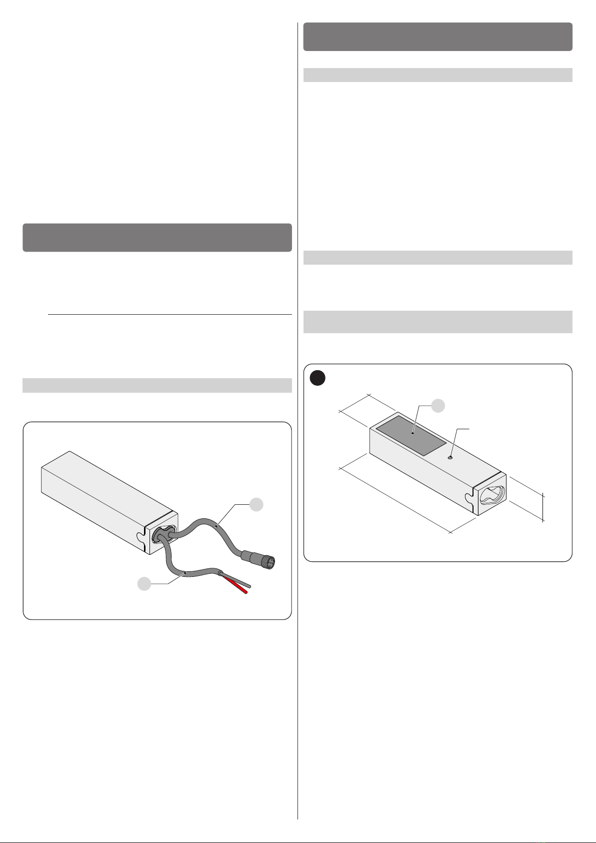
2 PRODUCT DESCRIPTION AND INTENDED USE . . . . . . . . . 3
2.1 List of constituent parts. . . . . . . . . . . . . . . . . . . . . . . . . . . . . . . . . . .3
3 INSTALLATION . . . . . . . . . . . . . . . . . . . . . . . . . . . . . . . . . . . . . 3
3.1 Pre-installation checks. . . . . . . . . . . . . . . . . . . . . . . . . . . . . . . . . . . .3
3.2 Product usage limits . . . . . . . . . . . . . . . . . . . . . . . . . . . . . . . . . . . . .3
3.3 Product identification and overall dimensions . . . . . . . . . . . . . . . . . .3
3.4 Product installation . . . . . . . . . . . . . . . . . . . . . . . . . . . . . . . . . . . . . .4
4 ELECTRICAL CONNECTIONS . . . . . . . . . . . . . . . . . . . . . . . . 4
4.1 Preliminary checks . . . . . . . . . . . . . . . . . . . . . . . . . . . . . . . . . . . . . .4
4.2 Electrical connections . . . . . . . . . . . . . . . . . . . . . . . . . . . . . . . . . . . .4
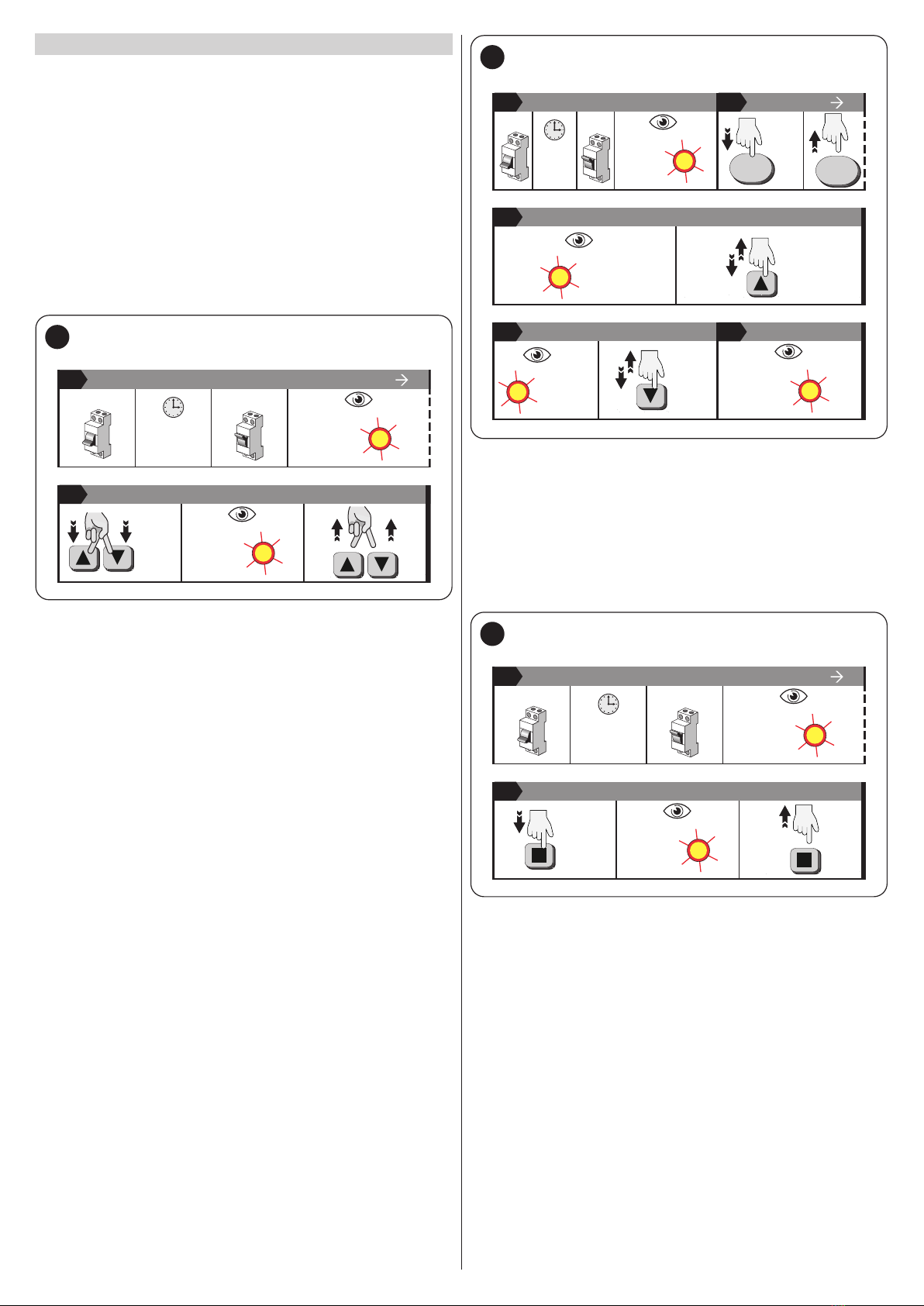
5 PROGRAMMING . . . . . . . . . . . . . . . . . . . . . . . . . . . . . . . . . . . 4
5.1 TWO-WAY and ONE-WAY operation . . . . . . . . . . . . . . . . . . . . . . . . .4
5.2 Transmitter pairings . . . . . . . . . . . . . . . . . . . . . . . . . . . . . . . . . . . . . .5
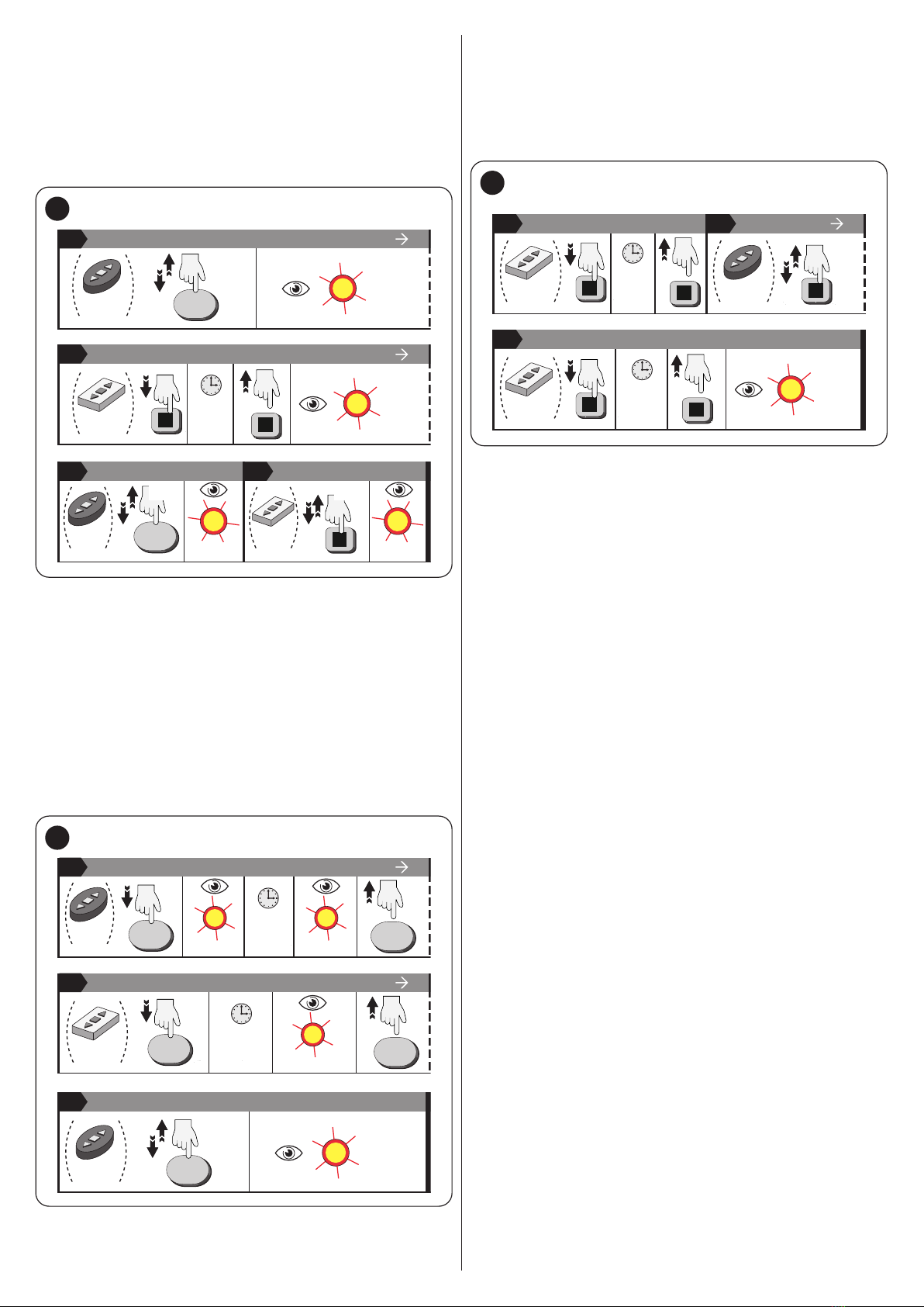
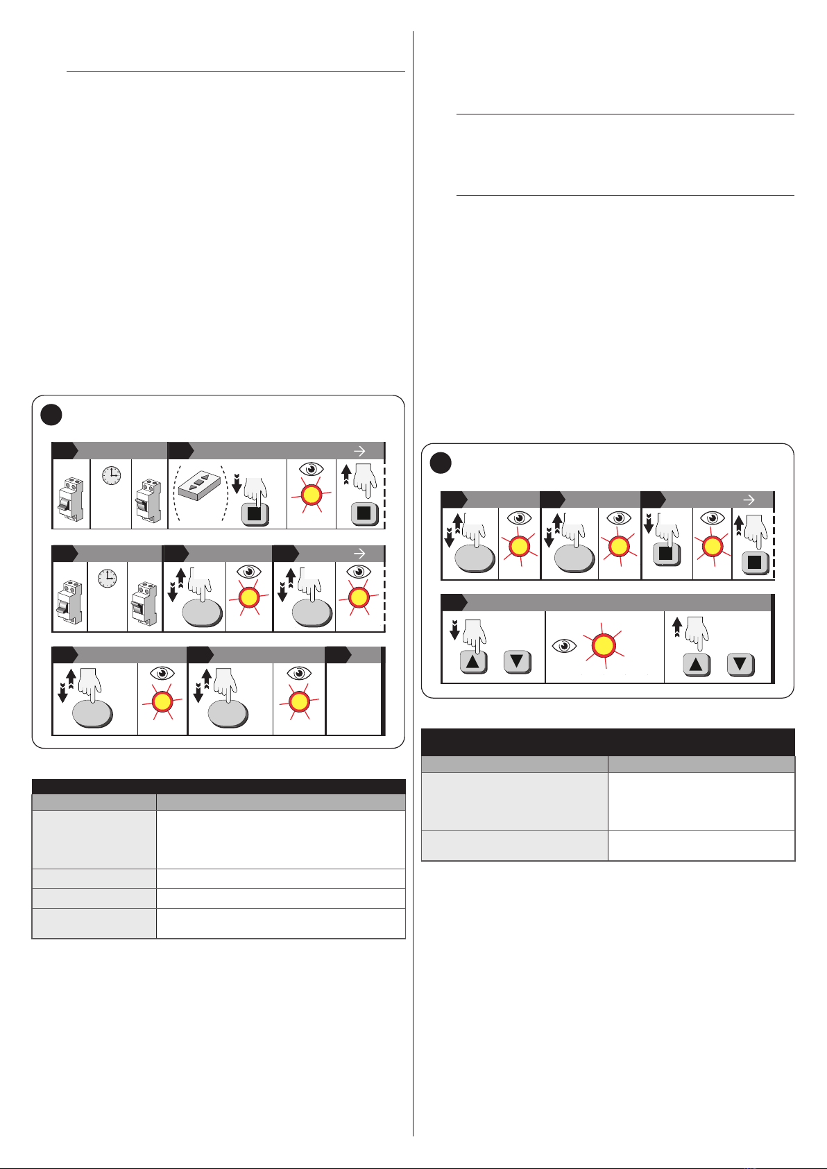
5.2.1 Memorising the FIRST TRANSMITTER. . . . . . . . . . . . . . . . . . . . .5
5.2.2 MEMORISING AN ADDITIONAL TRANSMITTER . . . . . . . . . . . . .5
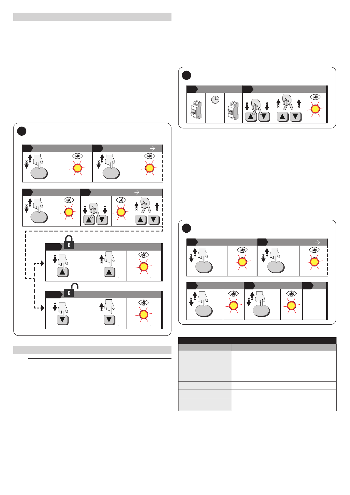
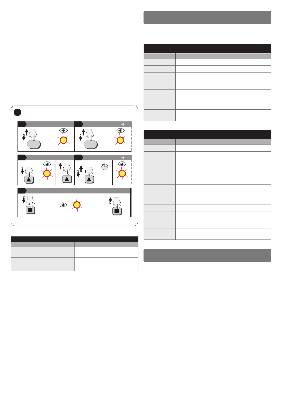
5.3 LOCKING AND UNLOCKING THE MEMORY . . . . . . . . . . . . . . . . . .7
5.4 DELETION PROCEDURES . . . . . . . . . . . . . . . . . . . . . . . . . . . . . . . .7
5.4.1 DELETION procedures (with MEMORISED transmitter) . . . . . . . .7
5.4.2 DELETION procedures (with NON-MEMORISED transmitter in
ONE-WAY mode) . . . . . . . . . . . . . . . . . . . . . . . . . . . . . . . . . . . . .8
5.4.3 Pre-defined (PRESET) or personalised (CUSTOM) colours . . . . . .8
5.4.4 Rotation speed of the RGB colours . . . . . . . . . . . . . . . . . . . . . . .9
6 COMMANDS FROM THE TRANSMITTER . . . . . . . . . . . . . . . 9
7 TESTING AND COMMISSIONING. . . . . . . . . . . . . . . . . . . . . . 9
8 PRODUCT MAINTENANCE. . . . . . . . . . . . . . . . . . . . . . . . . . 10
9 PRODUCT DISPOSAL . . . . . . . . . . . . . . . . . . . . . . . . . . . . . . 10
10 TECHNICAL SPECIFICATIONS. . . . . . . . . . . . . . . . . . . . . . . 10
10.1 Technical specifications . . . . . . . . . . . . . . . . . . . . . . . . . . . . . . . . . .10
10.2 Suggested power supply unit . . . . . . . . . . . . . . . . . . . . . . . . . . . . .10
11 CONFORMITY . . . . . . . . . . . . . . . . . . . . . . . . . . . . . . . . . . . . 10

ENGLISH – 3
–Cleaning and maintenance reserved for the user must not be
carried out by unsupervised children.
–Before intervening on the system (maintenance, cleaning), al-
ways disconnect the product from the mains power supply and
from any batteries.
–Check the system frequently.
–The packing materials of the product must be disposed of in
compliance with local regulations.
–Before connecting the power supply unit to the mains, make
sure that the LEDs are properly connected to the receiver.
–Incorrect connection of the LED diodes (reversed polarity) could
damage them, therefore be very careful to position the poles
correctly when connecting them.
–When it is switched on, the receiver resumes the same condition
prior to being switched off.
–The product must not be incorporated or installed in insulating
products such as mineral wool or polystyrene, or similar prod-
ucts.
PRODUCT DESCRIPTION AND INTENDED
USE
2
2 PRODUCTDESCRIPTIONANDINTENDEDUSE
Led Control Range TTDRGB is a “dimmer” combined with a radio re-
ceiver that is used to control RGB (Red-Green-Blue) LEDs. For it to work,
it must be powered by a 24 VDC external power supply unit (not supplied).
Through a paired transmitter it is possible to set the programmes. The
LEDs are controlled exclusively via radio through the paired transmitters.
a
CAUTION! – Any use other than that specied herein or in
environmental conditions other than those stated in this
manual is to be considered improper and is strictly for-
bidden!
2.1 LIST OF CONSTITUENT PARTS
The TTDRGB is made up of a casing that protects the command and
control boards. “Figure 1” shows the main parts making up the TTDRGB.
B
A
1
A Connection to the LED strips
B Connection to the 24Vdc power supply unit
INSTALLATION
3
3 INSTALLATION
3.1 PRE-INSTALLATION CHECKS
Before proceeding with the product’s installation, it is necessary to:
–check the integrity of the supply
–check that all the materials are in good working order and suited to the
intended use
–check that all operating conditions comply with that specied in the “
Product usage limits” paragraph and in the “TECHNICAL SPECIFI-
CATIONS” chapter
–check that the chosen installation location is compatible with the prod-
uct’s overall dimensions (see “Figure 2”)
–check that the surface chosen for installing the product is solid and can
ensure stable attachment
–make sure that the installation area is not subject to ooding; if neces-
sary, the product must be installed appropriately raised above ground
level
–check that the space around the product allows safe and easy access.
3.2 PRODUCT USAGE LIMITS
The product can be used exclusively with 24Vdc power supply units
and with 24 V LED strips of adequate power (refer to the “TECHNICAL
SPECIFICATIONS” chapter).
3.3 PRODUCT IDENTIFICATION AND OVERALL
DIMENSIONS
The overall dimensions and label (A) that allow for identifying the product
are shown in “Figure 2”.
98 mm
26 mm
20 mm
A
Tc point
2

4 – ENGLISH
3.4 PRODUCT INSTALLATION
To fasten TTDRGB (“Figure 3”):
1. position the box (A) and fasten it with bi-adhesive tape (B) (not
supplied)
2. make the electrical connections by operating as described in the
“ELECTRICAL CONNECTIONS” chapter.
A
B
3
ELECTRICAL CONNECTIONS
4
4 ELECTRICALCONNECTIONS
4.1 PRELIMINARY CHECKS
f
All electrical connections must be made with the sys-
tem disconnected from the mains electricity and with the
emergency power supply (if present in the automation)
disconnected.
a
The connection operations must only be carried out by
qualied personnel.
f
Mount a device on the electric power line that completely
disconnects the automation from the grid.
–The disconnection device must have contacts with a sufcient
gap to ensure complete disconnection, under the Category III
overvoltage conditions, in accordance with the installation in-
structions. If necessary, this device guarantees quick and safe
disconnection from the mains power and therefore must be
positioned in sight of the automation. If located in a concealed
position, it must be equipped with a system that prevents inad-
vertent or unauthorised reconnection of power, to avoid poten-
tial hazards.
4.2 ELECTRICAL CONNECTIONS
To make the electrical connections:
–connect the cable (A) to the chosen 24Vdc power supply unit
–connect the connector (B) to the LED strips.
A
1
2
4
3
B
4
Table 1
OUTPUTS TOWARDS LED STRIPS
PIN Exit RGB
1OUT 3 Blue
2OUT 1 Red
3OUT 2 Green
4Common (+)
l
For connecting multiple LED strips, make sure you use
suitable cables and adapters compatible with the con-
nector (B).
PROGRAMMING
5
5 PROGRAMMING
5.1 TWO-WAY AND ONE-WAY OPERATION
The Led Control Range can operate with both TWO-WAY and ONE-
WAY transmission. The transmission mode is determined by the rst trans-
mitter (ONE-WAY or TWO-WAY) paired with the system.
l
WARNING: if the system is new (has no transmitter mem-
orised), when it is switched on the paired LED strip will
emit a ash. Run one of the memorisation procedures for
the rst transmitter described in the paragraph “Memo-
rising the FIRST TRANSMITTER”. If the paired LED strip
does not emit any ash when the system is switched on,
it means that at least one memorised transmitter is al-
ready present.
OFF
OFF
ERA
P
ERA
W
ERA
P
BD
ERA
W
BD
NEW ON
BiDi
MONO
(x 1)
5

ENGLISH – 5
5.2 TRANSMITTER PAIRINGS
The functions and programming modes described below must be made
with a transmitter paired (memorised) with the system.
5.2.1 MEMORISING THE FIRST TRANSMITTER
5.2.1.1 TWO-WAY mode
RAPID PROCEDURE (only for memorising the rst transmitter)
To memorise the rst transmitter (“Figure 6”):
1. disconnect the power supply to the system. Wait 5 s. Power the
system again. One ash of the LED strips indicates that the system
has no paired transmitter
2. within 10 s from the power-up, simultaneously press pand qfor
3 s on the transmitter to be paired. Three ashes of the LED strips,
relative to the chosen channel, will conrm the correct pairing.
OFF ON
=
5sec
12
2End
(= 3s)
(x 1)
(x 3)
6
NORMAL PROCEDURE
To memorise the rst transmitter (“Figure 7”):
1. disconnect the power supply to the system. Wait 5 s. Power the
system again. One ash of the LED strips indicates that the system
has no paired transmitter
2. within 10 s from the power-up, press PRG for 5 s on the transmitter
to be paired. Over the next 2 minutes, all LED systems within the
radio range will start ashing, each for a random duration
3. choose the LED system involved in the programming and, with the
LED lit, press and release the p key (once)
4. in the LED system involved, with the LED lit, press and release the
q key (once)
5. the LED strip will ash three times to conrm the memorisation.
OFF ON
=
5sec
1 2 3
3
(= ON)
(= 5s)
PRG PRG
(x 1)
(x 1)
4End
(= ON)(x 3)
5
(x 1)
7
5.2.1.2 ONE-WAY mode
To memorise the rst transmitter (“Figure 8”):
1. disconnect the power supply to the system. Wait 5 s. Power the
system again. One ash of the LED strips indicates that the system
has no paired transmitter
2. within 10 s from the power-up, press ofor 3 s on the transmitter
to be paired. Three ashes of the LED strips, relative to the chosen
channel, will conrm the correct pairing.
OFF ON
=
5sec
12
2End
(= 3s)
(x 1)
(x 3)
8
5.2.2 MEMORISING AN ADDITIONAL TRANSMITTER
To perform the procedure described below, it is necessary to have a new
transmitter to memorise and an old previously memorised transmitter. The
two transmitters must have the “PRG” and “ESC” keys (such as, for exam-
ple, “ERA P” and “ERA W” series transmitters). The procedure memorises
all the keys of the new transmitter, in “Mode I”, replicating the same con-
guration of the old transmitter.
5.2.2.1 TWO-WAY mode
The system, congured to operate in TWO-WAY mode, can memorise up
to 30 transmitters.

6 – ENGLISH
To memorise the transmitter (“Figure 9”):
1. on the OLD transmitter: press and release the PRG key. The LED
strip will ash twice
2. on the NEW transmitter: press and hold the STOP key for 5 s
then release it. The LED strip will ash twice
3. on the OLD transmitter: press and release the PRG key. The LED
strip will ash twice
4. on the NEW transmitter: press and release the STOP key. The
LED strip will ash three times to conrm the memorisation.
(x 1)
(x 2)
12
2
OLD PRG
(x 2)
OLD PRG
(x 2)
NEW
=
5sec
3
3 4
NEW
(x 1)
(x 3)
(x 1)
End
9
5.2.2.2 ONE-WAY mode and transmitters having the “PRG”
and “ESC” keys
The system, congured to operate in ONE-WAY mode, can memorise up
to 30 transmitters.
To memorise the transmitter (“Figure 10”):
1. on the OLD transmitter: press and hold the PRG key. The LED
strip will ash twice and, after a brief pause, will emit two more
ashes. Release the PRG key
2. on the NEW transmitter: press and hold the PRG key for 7 s. The
LED strip will ash twice. Release the PRG key
3. on the OLD transmitter: press and release the PRG key. The LED
strip will ash three times to conrm the memorisation.
3
12
OLD
2
NEW
(x 2)
=
...
PRG
PRG
PRG
PRG
(x 2)
=
7sec (x 2)
3End
(x 1)
(x 3)
OLD PRG
10
5.2.2.3 ONE-WAY mode and transmitters lacking the “PRG”
and “ESC” keys
To memorise the transmitter (“Figure 11”):
1. on the NEW transmitter: press the okey for 7 s
2. on the OLD transmitter: press the okey 3 times
3. on the NEW transmitter: press the okey for 3 s. The LED strip
will ash three times to conrm the memorisation.
13
OLD
(x 3)
3End
NEW
=
7sec
2
(x 3)
NEW
=
3sec
11

ENGLISH – 7
5.3 LOCKING AND UNLOCKING THE MEMORY
Activating the memory lock allows for preventing the accidental and ran-
dom memorisation of other unintended or unauthorised transmitters.
To do this (“Figure 12”):
1. press PRG once on the transmitter. The paired LED strip will ash
twice
2. press PRG once on the transmitter. The paired LED strip will ash
twice
3. press PRG once on the transmitter. The paired LED strip will ash
three times
4. simultaneously press pand qfor 5 s. The paired LED strip will
ash four times. Release the buttons
5.
–to LOCK the memory press p for 5 s. The paired LED strip will ash
three times
–to UNLOCK the memory press p for 5 s. The paired LED strip will ash
ve times.
3 4
(x 1)
PRG
5a / 5b
5 a End
x 3
x 3
1 2
(x 1)
PRG
3
x 2
(x 1)
PRG
x 2
(= 5s)
x 5
(= 5s)
5 b End
(= 5s)
x 4
12
5.4 DELETION PROCEDURES
a
The deletion procedures are irreversible. The deletion
of one or more remote controls eliminates the settings
memorised in the system relative to the remote controls
themselves. The FULL deletion procedure restores the
system’s factory conditions. At the end of the procedure,
all settings previously memorised will be lost.
5.4.1 DELETION PROCEDURES (WITH MEMORISED
TRANSMITTER)
RAPID PROCEDURE (only for deleting ALL SETTINGS)
To do this (“Figure 13”):
1. disconnect the power supply to the system. Wait 5 s. Power the
system again
2. within 10 s from the power-up, press pand qfor 3 s. The paired
LED strip will ash ve times to conrm the deletion.
1 2 End
OFF ON
=
5sec
x 5
(= 3s)
13
NORMAL PROCEDURE
To do this (“Figure 14”):
1. press PRG once on the transmitter. The paired LED strip will ash
twice
2. press PRG once on the transmitter. The paired LED strip will ash
twice
3. press PRG once on the transmitter. The paired LED strip will ash
three times
4. press PRG once on the transmitter. The paired LED strip will ash
four times
5. press the keys indicated in “Table 2” to select the desired option
among those available. At the end of the procedure, the paired LED
strip will ash three or ve times to conrm the deletion.
1 2
(x 1)
PRG
3
x 2
(x 1)
PRG
x 2
3 4 5
(x 1)
PRG
x 3
(x 1)
PRG
x 4
(... see
the table
and press
the keys)
End
14
Table 2
DELETION
Buttons Setting
px 3 s
Deletion of a SINGLE REMOTE CONTROL:
after selecting this option, press oon the
remote control to be eliminated to complete the
procedure. The paired LED strip will ash ve
times
p+ qx 3 s Deletion of ALL SETTINGS
ox 3 s Deletion of ALL REMOTE CONTROLS
PRG FULL deletion (reset to the system’s factory
settings)

8 – ENGLISH
5.4.2 DELETION PROCEDURES (WITH NON-MEMORISED
TRANSMITTER IN ONE-WAY MODE)
l
In TWO-WAY mode, follow the procedure indicated in
the paragraph “Memorising the FIRST TRANSMITTER”,
sub-paragraph “TWO-WAY mode”.
To do this (“Figure 15”):
1. disconnect the power supply to the system. Wait 5 s. Power the
system again
2. within 10 s from the power-up, press ofor 5 s on the non-memo-
rised transmitter. The paired LED strip will emit two or three ashes
3. disconnect the power supply to the system. Wait 5 s. Power the
system again
4. press PRG once on the transmitter. The paired LED strip will ash
twice
5. press PRG once on the transmitter. The paired LED strip will ash
twice
6. press PRG once on the transmitter. The paired LED strip will ash
three times
7. press PRG once on the transmitter. The paired LED strip will ash
four times
8. press the keys indicated in “Table 3” to select the desired option
among those available. At the end of the procedure, the paired LED
strip will ash three or ve times to conrm the deletion.
OFF ON
=
5sec
OFF ON
=
5sec
13
3 4
2
NEW x 2
(= 5s)
PRG
6 7 8
(x 1)
PRG
x 3
(x 1)
PRG
x 4
(... see
the table
and press
the keys)
End
(x 1)
5
x 2PRG
(x 1)
x 2
6
15
Table 3
DELETION
Buttons Setting
px 3 s
Deletion of a SINGLE REMOTE CONTROL:
after selecting this option, press oon the
remote control to be eliminated to complete the
procedure
p+ qx 3 s Deletion of ALL SETTINGS
ox 3 s Deletion of ALL REMOTE CONTROLS
PRG FULL deletion (reset to the system’s factory
settings)
5.4.3 PRE-DEFINED (PRESET) OR PERSONALISED (CUSTOM)
COLOURS
The system leaves the factory (PRESET) with 8 pre-congured and avail-
able colours. Activating the “CUSTOM” function allows for memorising
personalised colours which can then be recalled.
l
After enabling the “CUSTOM” function, the personalised
intensity must be set using a memorised transmitter, as
explained in the “COMMANDS FROM THE TRANSMIT-
TER” chapter.
l
If the colours/intensities are set through the PRESET
function, refer to “Table 6”. If CUSTOM colours/intensi-
ties are set, refer to “Table 7”.
5.4.3.1 Setting through memorised transmitters
To activate the “PRESET/CUSTOM” function (“Figure 16”):
1. press PRG once on the transmitter. The paired LED strip will ash
twice
2. press PRG once on the transmitter. The paired LED strip will ash
twice
3. press o for 3 s. The paired LED strip will ash twice. Release o
4. press pfor 3 s or qfor 3 s to select the desired option among
those available in “Table 4”. If the pkey is pressed, the paired LED
strip will ash three times, while if the qkey is pressed the LED strip
will ash four times. Release the pressed key.
1 32
x 3
(x 4)
PRG
4
4End
( )
( )
(>3s)
x 2x 2
(x 1)
PRG
x 2
(x 1) (>3s)
16
Table 4
PRE-DEFINED (PRESET) OR PERSONALISED (CUSTOM) COLOURS/
INTENSITIES
Buttons Setting
px 3 s
PRE-SET colours (factory setting):
8 xed pre-set colours – red, green,
blue, hot/cold white, cyan, yellow,
magenta.
qx 3 s CUSTOM colours: customisable by
the user (factory setting: blue).

ENGLISH – 9
5.4.4 ROTATION SPEED OF THE RGB COLOURS
This function allows for varying the rotation speed of the RGB LED strip
colours. To activate rotation of the colours, refer to the “COMMANDS
FROM THE TRANSMITTER” chapter.
5.4.4.1 Setting through memorised transmitters
To do this (“Figure 17”):
1. press PRG once on the transmitter. The paired LED strip will ash
twice
2. press PRG once on the transmitter. The paired LED strip will ash
twice
3. press q for 3 s. The paired LED strip will ash three times. Release
q
4. press q (several rimes) until you select the desired option among
those available in “Table 5”. The paired LED strip will show the
selected behaviour after a short while
5. press o for 3 s to conrm the choice and exit the function. The
paired LED strip will ash three times. Release o.
3 4 5
5End
x 3
(3s) x 3
1 2
(x 1)
PRG
3
x 2
(x 1)
PRG
x 2
(x ...)(= 3s)
=
... (x ...)
17
Table 5
ROTATION SPEED OF THE RGB COLOURS
No. of button presses Setting
q(x 1) Speed 1 RGB (factory setting: 4
s - 1 s)
q(x 2) Speed 2 RGB (16 s - 6 s)
q(x 3) Speed 3 RGB (28 s - 10 s)
COMMANDS FROM THE TRANSMITTER
6
6 COMMANDSFROMTHETRANSMITTER
The table shown below summarises the keys to be pressed on the trans-
mitter for sending the main commands to the system.
Table 6
COMMANDS FROM THE TRANSMITTER WITH SETTING OF PRE-DEFINED
COLOURS (PRESET)
Buttons Channel activated
p(x 1) Lighting up at the last colour set
p(> 1 s) Increase of the light intensity
o- Stops rotation if colour rotation is under way
- Colour selection
q(> 1 s) Decrease of the light intensity
q(x 1) Switch-off
o+ pClockwise colour rotation
o+ qAnti-clockwise colour rotation
SLIDER + Increase of the light intensity
SLIDER - Decrease of the light intensity
Table 7
COMMANDS FROM THE TRANSMITTER WITH SETTING OF PERSONALISED
COLOURS (CUSTOM)
Buttons Channel activated
p(x 1) Lighting up at the custom colour for that channel
p(> 1 s) Increase of the light intensity
o
- Stops rotation if colour rotation is under way
- Selection of the personalised colour for that channel
- Anti-clockwise rotation of the colours if no
personalised colour has been set for that channel
q(> 1 s) Decrease of the light intensity
q(x 1)
- Switching off if the command arrives from the same
channel
- If the command arrives from another channel it
switches it on
o+ pClockwise colour rotation
o+ qAnti-clockwise colour rotation
p+ qSaving of the “custom” colour (the LED strip will ash
three times to conrm the memorisation)
SLIDER + Increase of the light intensity
SLIDER - Decrease of the light intensity
TESTING AND COMMISSIONING
7
7 TESTINGANDCOMMISSIONING
These are the most important phases of the automation set-up for max-
imising the system’s safety. The testing procedure can also be used to
periodically check the devices making up the system.
The sequence of steps to be performed when running the testing phase,
as described below, refers to a typical system.
To run the test:
1. verify that all the instructions stated in the “GENERAL SAFETY
WARNINGS AND PRECAUTIONS” chapter have been strictly
observed
2. using the control devices (transmitter), switch the LED strips on and
off to test them and verify that they behave according to their set
programme.

10 – ENGLISH
a
Commissioning can only be performed after all testing
phases have been successfully completed.
a
Before commissioning the system, ensure that the owner
is properly informed of all residual risks and hazards.
PRODUCT MAINTENANCE
8
8 PRODUCTMAINTENANCE
TTDRGB the electronic part does not require any special maintenance.
In any case, every 6 months the system should be checked to ensure the
entire system is working efciently.
PRODUCT DISPOSAL
9
9 PRODUCTDISPOSAL
l
This product is an integral part of the operator and must
therefore be disposed of with it.
As with the installation, only qualied personnel must dismantle the prod-
uct at the end of its life.
This product is composed of different types of materials. Some of these
materials can be recycled; others must be disposed of. Please enquire
about the recycling or disposal systems in place in your local area for this
type of product.
l
As indicated by the symbol shown
here, this product must not been
disposed of with household waste.
Separate the waste for disposal and
recycling, following the methods stip-
ulated by local regulations, or return
the product to the seller when pur-
chasing a new product.
a
WARNING
Some parts of the product may contain polluting or dan-
gerous substances. If not disposed of correctly, these
substances may have a damaging effect on the environ-
ment and human health.
a
WARNING
Local regulations may impose heavy penalties if this
product is not disposed of in compliance with the law.
TECHNICAL SPECIFICATIONS
10
10 TECHNICALSPECIFICATIONS
10.1 TECHNICAL SPECIFICATIONS
l
All technical specications stated in this section refer
to an ambient temperature of 20°C (± 5°C). Nice S.p.A.
reserves the right to apply modications to the product
at any time when deemed necessary, without altering its
functions and intended use.
Table 8
TECHNICAL SPECIFICATIONS
Description Technical specication
Power supply 24 Vdc (+/-10%)
Outputs 1 (RGB) x 24 Vdc (+/-5%)
Total maximum power See product label
Maximum output power 100W
Operating temperature -20°C ÷ +45°C
Reception frequency 433.92 MHz
Radio memory capacity (transmitters) 30
Protection rating IP55
Dimensions (L x D x H) 98 x 26 x 20 mm
l
The connecting cables must have an adequate cross-sec-
tional size for the maximum load applied. The output ca-
ble of the LED strips must not be longer than 2 m, in ac-
cordance with the EMC standard.
10.2 SUGGESTED POWER SUPPLY UNIT
Below are the characteristics of a power supply unit we suggest using:
–use a SELV LED control gear with constant voltage, certied according
to the IEC/EN 61347-2-13 standard, protected against short circuits.
Maximum power 240 W (Prated max 240 W).
CONFORMITY
11
11 CONFORMITY
SIMPLIFIED EU DECLARATION OF CONFORMITY
The manufacturer, Nice S.p.A., declares that the product LED CONTROL
RANGE is compliant with the directive 2014/53/UE.
The full text of the EU declaration of conformity is available at the following
internet address: https://www.niceforyou.com/en/support.

ENGLISH – 11
NOTES

www.niceforyou.com
Nice SpA
Via Callalta, 1
31046 Oderzo TV Italy
IS0836A00END_13-03-2023
Table of contents
Other Nice Lighting Equipment manuals
Popular Lighting Equipment manuals by other brands

Sygonix
Sygonix 1326052 operating instructions

Inspire
Inspire TIOPI N2128016-5-4K instruction manual

Heitronic
Heitronic Bedlight Installation and operating instructions

Drobo
Drobo 5D3 user guide

Aihomestyle
Aihomestyle QS-PLT595X595 Installation and instruction manual

SICK
SICK deTec4 Core Mounting instructions