Fotodiox Prizmo Jupiter I 8 User manual

1100 Lakeside Dr Gurnee , IL60031, United States
Toll Free:(866)812-1107
Local & International: (847)201-4623
Fax: (847) 261-0295
Http://www.fotodioxpro.com
Fotodiox Inc.
w w w . f o t o d i o x p r o . c o m
R
R
USER MANUAL
PZM-700R
JUPITER18

Introduction:
Thank you for choosing the Prizmo Jupiter 18 (PZM-700R) RGBWT light from Fotodiox. This light is designed with
all-aluminum frames for durability and enhanced heat dissipation. The PZM-700R is a compact, soft and efficient
multicolored LED panel. Prizmo lights are adjustable from 2800K to 10000k with adjustable green/magenta points
to optimize the spectrum for superb color effects. The PZM-700R can be controlled using the popular DMX512
protocol, with the optional remote control, via the built-in operations menus or with the optional mobile APP.
Warnings:
1.Do not disassemble the or modify the light.
2.Remove batteries when in storage.
3.When not in use for extended periods of time, DO discharge and recharge the batteries at least one time monthly.
4.Do not short circuit the batteries as this may seriously damage the batteries and increase risk of fire.
5.Do not drop or damage the batteries; doing so may increase risk of fire.
6.Do not burn the batteries; properly dispose of them according to local regulations.
7.Do not operate with wet hands, doing so may cause electric shock.
8.Use ONLY the provided AC power adapter; using other AC power adapters may result in damage to the light.
9.Do not operate in environments near flammable gasses or volatile liquids as this may increase the risk of explosion/fire.
10.Do not operate in enclosed spaces where heat buildup can be extreme, such as a car on a sunny day. The increased
heat may cause premature failure of the lighting unit.
11.Do not touch the plug or AC adapter with wet hands; doing so may cause electric shock.
12.Do not damage, disassemble, twist or modify the power cord as it may increase the risk of fire or electric shock.
13.Do not place under heavy objects.
14.Avoid impact to the LCD display.
15.Avoid dust and debris buildup as this will change the illuminance and color temperature.
16.Keep the light surface clean with a soft, dry cloth.
17.When hanging the light, always use the included safety cable.
Do not block the air inlet for the cooling fan. Doing so will inhibit heat dissipation and may cause excess noise
Characteristics:
1.Designed with an all-aluminum frame for durability and enhanced heat dissipation to help ensure a long product life.
2. Fully adjustable color temperature from 2800K to 10000K.
3. Complete 0-360° color selection.
4. Fully dimmable from 0-100%.
5. Multiple pre-programmed scenes and effects.
6. High CRI 93-98 , TLCI 95-97.
7. Can be powered via AC wall power or optional V-lock batteries.
8. Firmware upgradeable vie USB port.
9.Low heat LED technology provides high output without excessive heat.
10.DMX512 compatible.
11.Suitable for indoor or outdoor photography and videography. Great for studio or location shoots including live
broadcast, TV, film, portrait photography and more.
Light unit -1PC AC power adapter (144W)-1PC Power cord -1PC
DMX cable-1PC Safety cable-1PC Instruction manual-1PC
Bag -1PC
[Prizmo Jupiter 18 PZM-700R]
12 3
456
7
1 2
LED STUDIO LIGHT
LED STUDIO LIGHT
Prizmo Jupiter 18 PZM-700R
Packing List:
Optional Accessories:
Fabric Grid
Honeycomb grid
Remote control APP Mobile APP Soft diffuser
Prizmo Jupiter 18 PZM-700R

Diffused, luminous surface
Yoke
Yoke locking knob
V-lock battery plate
V-lock release button
Control panel
Stand mount locking screw
AA
C
B
3 4
LED STUDIO LIGHT
LED STUDIO LIGHT
AB
C
DEF
GHI
JK
H
G
F
A
B
J I
C
Control Panel Diagram:
DE
K
BD
F
E
G
SAT 0-100%
Intensity 0-100% Selector
DMX input
Operation shortcut buttons
(CCT, HSI, RGBWT, MENU, Filters, Special Effects, Scenes, BACK)
USB port Power switch Knob 1 – Intensity
Knob 2–SAT (saturation) Knob 3 – Selector (with touch button functionality) LCD screen
Indicator lights (2 indicators) 4-pin XLR socket
Parts Diagram:
DMX output
Power
ON
OFF
DMX IN
DMX OUT
CCT HSI RGBWT MENU
Filters Special Effect Scenes BACK
Battery
Data
G
C
E
F
D
Prizmo Jupiter 18 (PZM-700R)

Illuminance:Prizmo Jupiter 18 (PZM-700R)
Illuminance
Color temperature
NO.
2800K
5100Lux
1470Lux
418Lux
82Lux
3200K
5670Lux
1540Lux
440Lux
87Lux
5600K
6360Lux
1770Lux
508Lux
99Lux
10000K
5830Lux
1670Lux
460Lux
91Lux
0.5m
1m
2m
5m
Red
1520Lux
440Lux
127Lux
4400Lux
1270Lux
360Lux
770Lux
210Lux
63Lux
0.5m
1m
2m
Green Blue
25Lux 72Lux 12Lux5m
5 6
LED STUDIO LIGHT
LED STUDIO LIGHT
Distance
Specifications:
1
2
3
4
5
6
7
8
9
10
11
12
13
14
15
16
17
18
19
95-97
93-98
Diffusion panel
ø ø16.0in ( 407mm)
Full RGB+WT gamut with 360° HSI control
0-100% continuous
Continuously adjustment 2800K-10000K
+/-200K
AC100-240V, 50/60Hz,DC15V
100W max
V-lock
DC12-17V
0-80%
-4 to 113°F (-20-45℃)
Up to 50,000 hours
7.78lbs (3.53Kg)without adapter,9.41lbs (4.27Kg) with adapter
1inx22.0inx2.9in(510x560x75mm)
Name
DMX 512,Remote control,Mobile APP
120°
IP20
Optical system
Light emis surface
Beam angle
Color (Hue Saturation Intensity)
Intensity/brightness
White light
CRI
TLCI
Color temperature error
Remote control
Power input
Power output
Battery mount
Output on battery power
Working temperature
Protection level
LED lifetime
Weight
Dimensions
1.Use the Honeycomb Grid
(1) Insert the bottom of the honeycomb grid into the slots on the left and right buckles at the bottom edge of the
frame of the light body; then insert the top of the honeycomb grid into the left and right buckles at the top edge
of the frame.
(2) After installation, check the buckles to ensure the grid is securely in place.
(3) To remove the honeycomb grid, open the upper two buckles, and carefully pull the honeycomb grid from the
buckles.
Operating Instructions:
1.Set-up instructions:
(1) Loosen the stand mount locking screw by turning counterclockwise until you can place the light onto the stand
or stud. Turn the stand mount locking screw clockwise to secure on stud.
(2) When mounting to a 1 1/8” stud, it will be necessary to remove the set screw.
Battery power
Prizmo Jupiter 18 (PZM-700R)
Illuminance
Color
Distance
20
3.When hanging the light, always use the safety cable. Looping the through the yoke and the external support from
which the light is hanging; connect the ends of the cable with the provided carabiner.
JUPITER 18
w w w . f o t o d i o x p r o . c o m
R
JUPITER 18
w w w . f o t o d i o x p r o . c o m
R
Stand mount locking screw

(1) Insert the 4-pin XLR plug output from the AC power adapter into the 4-pin XLR socket on the lower left corner
of the control panel. Attach the power cord to the AC power adapter.
(2) Connect the AC power adapter to the external AC power (AC100V-240V) You will now be able to power your
light and view real-time data on the LCD display.
5.Connecting the power supply
7 8
LED STUDIO LIGHT
LED STUDIO LIGHT
SAT 0-100%
(1) The V-lock mount is pre-installed on the AC power adapter.
(2) Install the power adapter with V-lock plate on the back of the light. It is successfully installed when you hear the lock
mechanism click.
4.Installing the AC power adapter
(3) To remove the adapter, press down on the V-lock release button and push the adapter out of the V-lock plate.
6.Battery Power
Insert your V-lock
battery (sold separately) into the V-lock plate. To remove the battery, press the release button and slide the battery
out in the opposite direction.
When the battery is used to
power the light, the maximum output power is reduced to 80%.
This product can be powered by an external battery attached to the product's built in V-lock plate.
Note: The PZM-700R operates on 1 battery with an output power of 150W or more.
2.Saturation Knob:
3.Intensity knob:
Functions of the control knobs:
1.Selector Knob:
Rotate the selector knob to select the desired mode in the menu, press once to select.
In certain modes, parameters such as CCT, CMB, SPD, and Frq may be adjusted using this knob.
In HSI, CCT, RGBWT mode, press the knob for several seconds to save the current settings.
Selector Knob
In the HSI mode, SAT can be adjusted 0-100%. In other modes,
parameters such as SAT, CMB, Col, may be adjusted using this knob.
Attaching the adapter Removing the adapter
Adjusts brightness from 0-100% in any mode (0-80% when using battery power)
Brightness 0-100%
JUPITER 18
w w w . f o t o d i o x p r o . c o m
R
JUPITER 18
w w w . f o t o d i o x p r o . c o m
R
JUPITER 18
w w w . f o t o d i o x p r o . c o m
R
JUPITER 18
w w w . f o t o d i o x p r o . c o m
R

When the device requires a software upgrade, you can connect a USB flash drive through the USB port.
(Upgrade software can be downloaded from www.fotodioxpro.com)
WELCOME TO USE
MENU
1.
2.HSI
3.RGBWT
4.Filters
5.Special Effect
6.Scenes
7.Lang
8.DMX Settings
9.RMT Settings
CCT
9 10
LED STUDIO LIGHT
LED STUDIO LIGHT
USB
3.USB port operation:
Operation:
(1) Download the updates to an USB flash drive from
(2) Remove the dustproof plug from the USB port and insert the USB flash drive with the upgrade program.
(3) Power on; the DATA indicator light will flash. The upgrades is complete when the “Welcome” message appears
in the LCD display.
(4) It takes about 15 seconds to finish upgrading . After the upgrade is complete, remove the USB flash drive and replace
the dustproof plug.
www.fotodioxpro.com
1.Battery indicator
When the battery indicator light is on: the V-lock battery is being used to power the light.
When the battery indicator light flashes: the V-lock battery is running low.
When the battery indicator light is off: the AC power adapter is being used to power the light.
Note: when the battery is used to power the light, the max output power is reduced to 80%.
2.Data indicator
When the data indicator is on: the DMX512 remote control function is being used.
When the data indicator flashes: the USB port is being used for data upgrade.
The data indicator flashes once each time the light receives an effective remote control signal.
Operating Instructions:
1.Use the Selector knob to highlight the desired sub-menu option, press the knob once to select.
2.In the main menu, you may also press the operation shortcut buttons to enter a menu option directly.
There are nine modes: CCT, HSI, RGBWT, Filters, Special Effects, Scenes, Language, DMX channel
setting and Remote control channel setting.
3.From any of the menus, press the BACK button to return to the previous menu. You may also enter
the main menu using the MENU button.
Main menu
(Boot display Welcome message.)
1.LCD display screen and menu instructions: Indicator function description:
Battery
Data
FOTODIOX

[Menu function instructions:]
11 12
LED STUDIO LIGHT
LED STUDIO LIGHT
Use the selector knob to highlight the desired effect. Push the knob once to enter. Use the selector,
saturation and intensity knobs to adjust the parameters.
*OFF
*Party effect
-----SPD (speed): 0-100% SAT: 0-100% INT: 0-100%
*Candle
-----SPD: 0-100% COL: warm / warm white / white INT: 0-100%
*Clouds
-----SPD: 0-100% INT: 0-100%
*Club lights
-----SPD: 0-100% COL: 03-24 INT: 0-100%
*Color chase
-----SPD: 0-100% SAT: 0-100% INT: 0-100%
*Cop car
-----CMB(combination): R+B+W/B+W/R+B/B INT: 0-100%
*Fire
-----SPD: 0-100% INT: 0-100%
*Fireworks
-----FRQ(frequency): 0-100% CMB: COLOR/WHITE/C+W INT: 0-100%
*Lightning
-----SPD: 0-100% INT: 0-100%
R3202 9203
R3203 2219
R3204 2418
R3206 0828
R3208 0925
R3216 2209
R3220 6506
R3407 9701
R3411 9901
R3408 4208
R3409 9304
R3410 9301
3420 9300
3441 3009
34429008
3443 9002
3444 9000
3304 3007
3315 7018
3316 9013
3317 9012
3308 3006
3309 8008
3313 9003
FOTODIOX No.
0328
1228
1218
2218
2118
2108
0586
9101
9103
6106
3108
3109
9100
9201
9206
3208
4108
6408
2208
2109
2106
4009
3008
4008
Description
CTB
3/4 CTB
1/2 CTB
1/3 CTB
1/4 CTB
1/8 CTB
2X CTB
CTO
3/4 CTO
1/2 CTO
1/4 CTO
1/8 CTO
2X CTO
CTS
1/2 CTS
1/4 CTS
1/8 CTS
GREEN
1/2 GREEN
1/4 GREEN
1/8 GREEN
MAGENTA
3/4 MAGENTA
1/2 MAGENTA
07 CYAN
15 CYAN
30 CYAN
60 CYAN
90 CYAN
15 RED
30 RED
60 RED
90 RED
15 GREEN
30 GREEN
60 GREEN
90 GREEN
15 YELLOW
30 YELLOW
60 YELLOW
90 YELLOW
15 MAGENTA
30 MAGENTA
60 MAGENTA
90 MAGENTA
15 PINK
30 PINK
60 PINK
430
431
433
436
439
441
443
446
449
451
453
456
459
461
463
466
469
471
473
476
479
481
483
486
7
5
0
0
0
5
0
0
0
5
0
0
0
5
0
0
0
5
0
0
0
5
0
0
5.Filters
Filter comparison table
3314 9001
3318
3310
3118
2107
9102
1/4 MAGENTA
1/8 MAGENTA
90 PINK
4890
3310
Rosco Description
Rosco
4.Special effect
3.RGBWT
RGBWT selection -------------------------------------adjust using the “Selector ” knob
Red: 0-100% ------------------------------------------adjust using the “Intensity” knob
Green: 0-100% ---------------------------------------adjust using the “Intensity ” knob
Blue: 0-100% ------------------------------------------adjust using the “Intensity”knob
White: 0-100% ----------------------------------------adjust using the “Intensity ” knob
Tungsten: 0-100% -------------------------------------adjust using the “Intensity” knob
1.CCT (color temperature)
M1, M2, M3, M4, M5----------------switch data back and forth with the “Select” knob
CCT (color temp.): 2800K-10000K --------------------adjust using the"selector" knob
GN:-1/+1--------------------------------------------adjust using the “saturation” knob
INT : 0-100% ---- -------------------------------------adjust using the “intensity” knob
2.HSI
R+G+B, R+G, R+B, G+B ----------switch back and forth with the “Selector”knob
HUE: 0-360゜ ---- -----------------------------------adjust using the “Selector” knob
SAT (saturation): 0-100% --------------------------adjust using the “Saturation” knob
INT (intensity): 0-100% ----------------------------- adjust using the “Intensity ” knob
FOTODIOX No.

13 14
LED STUDIO LIGHT
LED STUDIO LIGHT
DMX single light connection diagram
1 2( 1-3( 1-4( 1-5 1-6 1-7 1-8- brightness) color temperature) red/green deviation) (sat) (red) (green) (blue)
1-16( 2-1( 2-2( 2-3 2-4 2-5 2-6brightness) color temperature) red/green deviation) (sat) (red) (green) (blue)
2-1( 2-2( 2-3( 2-4 2-5 2-6 2-7brightness) color temperature) red/green deviation) (sat) (red) (green) (blue)
32-10( 32-11( 32-12( 32-13 32-14 32-15 32-16brightness) color temperature) red/green deviation) (saturation) (red) (green) (blue)
8 Bit
10 Channels
1-1( )1-2( )1-3( )1-4( ) 1-5( ) 1-6( ) 1-7( )brightness color temperature red/green deviation sat red green blue
1
2
16
17
506
507-512
light
DMX multiple light connection diagram
11.DMX connection
When operating DMX, connect the DMX cable to the console (the specific wiring is shown in the diagram
below), then set the DMX address to match the console address.
12.DMX control: First, the menu needs to be switched to the DMX control interface.
Note: Seven channels are required for proper DMX control over all parameters.
For example:
In DMX address setting 1, 1-1 is brightness control, 1-2 is color temperature control, 1-3 is red and green
deviation control, 1-4 is saturation control, 1-5 is monochrome red control, 1-6 is monochrome green
control, and 1-7 is monochrome blue control.
All Fotodiox products are backed by a 24 month limited warranty.
DMX address comparison table:
LCD display address
DMX console channels
DMX console512
light 1 light 2 light 3
DMX console512
6.Scenes
Use the selector knob to highlight the desired mode. Push the knob once to enter. Use the selector, saturation
and intensity knobs to adjust the parameters.
*Mode ONE [M1 M2 M3 M4 M5]
-----(CCT mode) CCT:2800-10000 K INT: 0-100%
*Mode TWO G+B, R+G+B, R+G, R+B
-----(HSI mode) HUE: 0-360゜, SAT: 0-100% INT: 0-100%
*Mode THREE
-----(RGBWT mode) Red: 0-100% Green: 0-100% Blu: 0-100% W:0-100% T: 0-100%
GN: -1 / +1
7.[Lang] (language)
Use the selector knob to highlight the desired language. Push the knob once to select.
*English
*Chinese
8.DMX settings
Adjust the DMX address using the selector knob, push the knob to select the address.
DMX Address: 001-512
9.RMT settings (remote control settings)
Remote control operating instructions:
1.On the light, go to menu and enter RMT settings. Set the desired wireless receiving address from 0-511.
2.On the remote control, go to menu and enter RMT settings. Set the desired wireless receiving address from 0-511.
3.Make sure the wireless receiving address on the light matches the light receiving address on the remote control.
The remote control can control multiple lights at the same time.
4.The wireless remote control has a working distance of approximately 65 feet (20 meters).
Note: After setting the wireless receiving address in the RMT settings on the light, you cannot change the address
through the remote control. You can only manually adjust it through the RMT settings on the light.
10.Factory reset
To restore the light or remote control to factory settings:
Press and hold the MENU button on the light or on the remote control for more than 4 seconds in the main menu
on the light, the entire device will reset, and the data will be restored to the factory setting state.
This manual suits for next models
1
Table of contents
Other Fotodiox Lighting Equipment manuals

Fotodiox
Fotodiox PopSpot 50 v.2 User manual

Fotodiox
Fotodiox DaoLite Prizmo Edition DLC-2 User manual

Fotodiox
Fotodiox Pro Softbox User manual

Fotodiox
Fotodiox PopSpot Ultra 100 User manual

Fotodiox
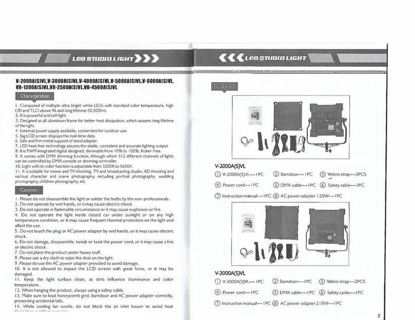
Fotodiox V-2000AVL User manual

Fotodiox
Fotodiox SkyFiller Wings SFW-150SS User manual

Fotodiox
Fotodiox FACTOR Prizmo 150 User manual

Fotodiox
Fotodiox WonderPana 145 User manual

Fotodiox
Fotodiox Skyfiller Wings Series User manual

Fotodiox
Fotodiox WIDE ANGLE Series User manual