PoolRite Surechlor 4000 User manual

Warranty Card
EQUI
P
M
ENT
EQUI
P
M
ENT
owners
manual
SURECHLOR 4000
Pool Management System
Poolrite Equipment Pty Ltd
A.B.N. 11 001 674 004
Poolrite Equipment Pty Ltd Poolrite Equipment Pty Ltd
415 Creek Road, 6 Forsyth Close,
P.O. Box 520, P.O. Box 7055,
Mt Gravatt QLD 4122 Australia
Wetherill Park N S W 2164 Australia
Tele hone: (07) 3323 6555 Tele hone: (02) 9729 0166
Facsimile: (07) 3323 6500 Facsimile: (02) 9729 2759
Poolrite Equipment Pty Ltd Poolrite Equipment Pty Ltd
15 Yiannis Court, Unit 10/16 Ledgar Road,
Springvale VIC 3171 Australia Balcatta W A 6021 Australia
Tele hone: (03) 9547 4188 Tele hone: (08) 9344 3871
Facsimile: (03) 9547 1023 Facsimile: (08) 9345 3923
Poolrite Equipment Pty Ltd Poolrite Equipment Pty Ltd
36 Hugh Ryan Street, Unit 22, 761 Great South Road,
Garbutt QLD 4814 Australia Penrose Auckland
Tele hone (07) 4779 4880 New Zealand.
Facsimile (07) 4779 6714 Tele hone: (09) 571 0210
Facsimile: 0800 766 574
Item No. 21619 (08/04)
Stella Print

WARRANTY CARD
Surechlor 4000 Salt Water Chlorinator
Poolrite Equipment Pty Ltd
Your Poolrite Surechlor 4000 is manufactured to the highest ossible standards and
most u -to-date technology.
Accordingly the equi ment carries the following Warranty, should a fault occur due to
faulty manufacture or materials.
Important
In the event of a fault covered by Warranty occurring, the Purchaser must, in the first
instance, contact Poolrite Equi ment Pty. Ltd. or the closest authorised Poolrite
Distributor. Poolrite Warrant the original urchaser of the Power Pack and Electrolytic
Cell for a eriod of 12 months from the Date of Purchase by the original Owner,
should examination disclose to its satisfaction that the Cell or Power Pack has failed
due to faulty manufacture or materials. In addition for a further eriod of 24 months the
Electrolytic Cell will be re aired or re laced at Pro Rata cost from Date of urchase
by the original Owner.
The Warranty is void if the following occur:
1. Damage resulting from matters beyond Poolrite’s control.
2. The Cell or Power Pack has been installed incorrectly and not in accordance with
these instructions.
3. The Power Pack has been connected to a ower su ly other than 240 volt 50 Hz.
4. The Cell or Power Pack has been used for any ur ose other than swimming ool
or s a sterilisation.
5. Water above the tem erature of 45°C has been ermitted to flow through the Cell.
6. Water has not been ermitted to flow freely through the Cell when turned on.
7. The safety flow detector or connections have been tam ered with.
8. The Power Pack has been serviced by a erson other than a erson authorised to
do so by Poolrite or it’s agent.
9. The Cell ower terminals have been submersed in acid solution when cleaning.
10. Non-swimming ool grade salt has been used in the ool.
This Warranty is a licable to workmanshi and materials. Poolrite will re air or re lace
at no charge, all arts returned freight aid, which dis lay faulty workmanshi or
materials.
Poolrite Equi ment Pty. Ltd. acce ts no res onsibility for loss, damage or injury to
erson or ro erty arising from Warranty failure of equi ment, or installation of that
equi ment. Unless with the ex ress rior authority of Poolrite, any re air or re lacement
shall be rovided only by Poolrite or it’s authorised distributors and this Warranty shall
not extend to any ex enditure otherwise incurred.
Warranty Card
Name of Purchaser
Address
Purchased From
Date
Equi ment and Model
IMPORTANT: This card must be filled in and
returned to Poolrite Equi ment Pty. Limited
within 14 days of urchase to render the
Warranty effective.
Queensland Head Office
Sales & Export Brisbane
415 Creek Road,
P.O. Box 520,
Mt. Gravatt. QLD 4122
Tele hone: (07) 3323 6555
Facsimile: (07) 3323 6500
Poolrite Equipment Pty Ltd
Unit 22, 761 Great South Road,
Penrose. Auckland
New Zealand.
Tele hone: (09) 571 0210
Facsimile: 0800 766 574
Poolrite Surechlor 4000
Power Pack Controls
and Connections

INDEX
INSTALLATION INSTRUCTIONS 2
Surechlor 4000 Cell 2
Surechlor 4000 Power Pack 3
Connecting The Pool Pump 4
Off-Peak Installations 4
Adding Sal To The Pool 4
Marble Plaster Surface Pools 4
Calculating Pool Capacit 5
Calculating Salt To Be Added 5
Salt Calculation Chart 6
Adding Salt and Stabiliser 6
Dissolving The Salt 6
When The Salt Has Dissolved 6
SETTINGS AND CONTROLS 7
Chlorine Control — All Models 7
Monitor — All Models 7
OPERATING INSTRUCTIONS 7
Using the Salt Test 7
Using Super Chlorination 7
Using Manual Control 7
Setting The Time 8
Setting The Winter Modes 8
Changing The Settings 8
Accessing the S stem Histor 8
Messages 8
HOW YOUR SURECHLOR 4000 WORKS 9
MAINTENANCE OF POOL CHEMISTRY 9
Chlorine Level 9
pH Control 9
Adding Acid 10
Total Alkalinit 10
C anuric Acid Stabiliser 10
Calcium Hardness 10
MAINTAINING SALT LEVELS 10
MAINTENANCE OF YOUR SURECHLOR 11
Cell Cleaning 11
How Long Should Your Cell Last 12
Common Causes of Premature Cell Failure 12
Customer Responsibilities 12
Operational Check List 13
ELECTRICAL SPECIFICATIONS 14
APPENDIX A — MENU TREE 15 & 16
WARRANTY
1

INSTALLATION INSTRUCTIONS
OWNERS MANUAL
Please hand this Owner’s Manual to the pool owner after installation is completed as it
contains the Warrant Card and vital information for correctl maintaining the pool and
this product!
SURECHLOR CELL
Ideall , the electrol tic cell
should be installed in a position
with 1.5 metres of a vertical wall
or fence to allow the Power
Pack to be easil mounted
without the need to provide an
additional post.
The cell must be installed
horizontall (level) within 5°, in
the return to pool line, with the
two plumbing ports and arrow
on label pointing down.
The water can flow in either
direction through the cell.
Heaters and other equipment in
the return to pool line must be
before the cell i.e. between the
cell and filter.
If an air blower is fitted to an air
inlet for venturi jets, precautions
must be taken to prevent gases
generated in the Surechlor cell
from accumulating in the blower
and associated pipework.
The recommended wa of achieving this is to install an inverted loop in the air line with
a 3mm (max.) diameter hole in the top venting to atmosphere.
2

3
The diagram below shows the general arrangement for this loop.
Vented Loop
Warning: The Warrant will be void if the cell is not installed exactl as specified.
SURECHLOR POWER PACK
The Power Pack Enclosure is approved and rated to Degree Of Pro ec ion IP24 and
therefore can legall be installed in the Pool Zone as defined in the AS/NZS 3000
Wiring Rules. It mus be mounted on a vertical wall or fence within 1.5 metres of the
cell and at least 1 metre above the ground. Also, it mus be in a position to allow its
suppl lead to be plugged into a 10 amp 240 volt power point.
Remember the filter pump must be plugged into this Power Pack.
Start b selecting a suitable place to attach the Mounting Bracket using the two screws
provided. The Mounting Bracket must be fixed with the screws horizontal and the vent
louvres above the screws facing upwards.
If no suitable wall is available, then install a 100mm x 100mm hardwood post with a
vertical mounting board 400mm wide x 300mm high x 18mm thick attached.
Hook the Power Pack onto the Mounting Bracket b the top edge at the rear of the box.
When secure, plug the power lead into a suitable 240 volt power point but do not switch on.

CONNECTING THE POOL PUMP
●Plug the pool pump into the pump socket at the bottom of the unit.
(see No e below about the use of large or 3 phase pumps).
Off-Peak Ins alla ions
This unit is suitable for off-peak tariff suppl .
Warning: The Warrant will be void if the Power Pack is installed or operated .....
a) on, or less than 1 metre from the ground.
b) in a position where flooding from ground water could occur.
c) where the airflow is obstructed, i.e. within an unvented auxiliar enclosure.
d) with a load (pump) connected to the 240 volt pump outlet socket greater than
1.5kw (continuous).
e) from an electrical suppl socket which is not rated to suppl 10 amps at 240 volts
50Hz and is not adequatel protected b the correct size fuse or circuit breakers.
No e: If a pump load greater than 1.5Kw or the use of a 3 phase pump is required, an
interface rela must be installed.
If double adaptors or stackable plugs are emplo ed to operate more than one pump
directl from this Pump Outlet Socket the Warrant will be void.
Please refer to our Poolrite State Office for details.
ADDING SALT TO THE POOL
S ar up procedure for marble surface pools
For new concrete pools with marble plaster (marblesheen) finishes we recommend that
the salt not be added to the pool until the excess calcium compounds in the plaster
have leached out and the pH of the water has stabilised.
4

The recommended stabilising period is:
●For hand mixed/applied plaster 12 weeks.
●For machine mixed/applied plaster 24 weeks.
During this period the pool should be sterilised with liquid chlorine.
Calcula ing Pool Capaci y
Swimming pool grade salt (low mineral content Sodium Chloride) must be added to the
pool and allowed to completel dissolve before operating the chlorinator cell.
The amount of salt to be added cannot be calculated until the volume of water
contained in the pool is determined.
This water volume can be obtained b :
(a) Referring to the pool manufacturer’s data (if pre-moulded fibreglass).
(b) Reading the difference on the water meter before and after filling.
(c) B mathematical calculation.
Formula For Calcula ing Wa er Volume
Water Volume (m3) = [Surface Area (m2) x Average Depth (m)] minus [Volume occupied
b steps, swim-outs, etc.]
Calcula ing Sal To Be Added
The amount of salt to be added to the calculated volume of water in the pool depends
on the salt concentration selected.
Sal Quan i y (kg) = Wa er Volume (m3) x Sal Concen ra ion (mg/l)
1000
For example, if the calculated volume of water in our pool is 60.0 cubic metres (as per
previous example) and the minimum salt level of 6000 mg/l is required (for cool
climates), the amount of salt needed will be:
Salt Quantit = 60 x 6000
1000
= 360 kg
Wha Sal Concen ra ion To Use
Although our Surechlor 4000 has been designed to operate with a wide range of salt
concentrations, the minimum recommended level is 6000 mg/l (P.P.M.). However with
heated and outdoor pools in tropical and sub-tropical climates, salt levels between
7000 and 8000 mg/l can be maintained in order to gain the benefits of increased
chlorine output, reduced cell maintenance and extended cell life.
The Chlorine Control can be switched to 100% output if higher salt levels are used
without the risk of damage occurring, due to the incorporation of electronic output
limiting on all of these model chlorinators.
To make the calculation easier, we have provided the chart on the following page.
5

6
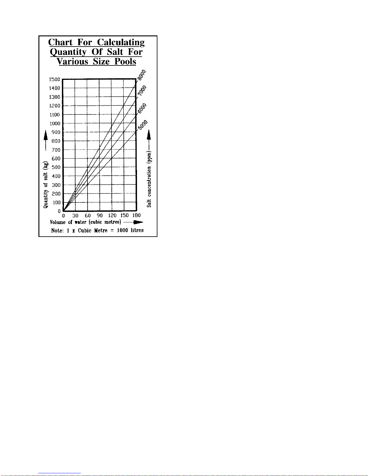
To find he correc amoun of sal using his char :
1. Mark the point along the bottom edge which
corresponds with the calculated volume of
water in the pool.
2. Draw a vertical line from this point which
intersects the inclined lines showing salt
concentrations.
3. From the point where this vertical line
intersects the inclined line showing the chosen
salt concentration, draw a horizontal line
across to the left. Where this line crosses the
left side of the graph, the quantit of salt in
kilograms will be indicated.
Adding Sal And S abiliser To The Pool
If ou are quite sure of our calculations then add
the calculated amount of salt directl to our pool.
Warning:
Onl swimming pool grade salt (Sodium
Chloride) should be used. Inferior grades ma
lead to problems with the chlorinator cell.
Do not attempt to add salt via the surface skimmer
as this can cause damage to the filtration s stem.
An suction t pe pool cleaners should also be
disconnected before adding salt.
At the same time add the recommended quantit of cyanuric acid s abiliser. This is
most important as our Surechlor will not operate efficientl during summer months
without the correct level of stabiliser in the pool. Recommended level for maximum
efficienc is between 30 and 60 mg/l (ppm). pH buffer can also be added now if required.
Dissolving The Sal
Before attempting to operate the Surechlor 4000 cell, the salt must be allowed to full
dissolve in the pool water. This is the best achieved (after allowing sufficient time for
the glue on the pipe fittings to set properl ) b running the filter pump without the cell
operating for 24 hours to circulate the water.
To assist the dissolving of the salt, regularl brush the floor of the pool with a pool
broom until the salt has dissolved.
When The Sal Has Dissolved
With the pump still operating, increase the Chlorine Control to maximum. The Monitor
should indicate 10 bars.
Your Surechlor is now generating chlorine!
Should the Output Monitor read low with the Chlorine Control at maximum, do not be
concerned, just allow the s stem to run for another 24-48 hours. If the displa
continues to give a low reading after this period, press the Salt Test (with the s stem
running) and note the displa message.
If the water temperature is around 25°C and the cell is relativel clean, this reading will
indicate salt concentration. If it confirms the salt level is low then add more salt
graduall over a period of da s until the displa reads normal. Continue brushing floor
of pool until the additional salt has dissolved.

SETTINGS AND CONTROLS
CHLORINE CONTROL — all models
Because our Surechlor 4000 has been designed to operate over a wide range of salt
levels, water temperature, running time, etc., a Chlorine Control has been provided to
compensate for these variations.
When first starting the unit and where maximum chlorine production is needed the
output should be set to maximum.
The Chlorine Control on all Surechlor 4000 models can be set to maximum if higher
salt levels are used without the risk of damage occurring, due to the incorporation of
electronic output limiting.
To operate the filter pump onl without the cell, press the menu button until “Manual
Control” appears on the displa and press enter.
Press enter until “Pump” appears.
Press ∧or ∨to turn the pump on or off.
OUTPUT MONITOR
This multi-function displa has been provided to allow monitoring of the current
passing through the electrol tic cell to allow ou to gauge the operation of the cell and
the chlorine production. This assists in determining the condition of the electrol tic cell.
The output ma be adjusted with the up ∧or down ∨buttons, from 10% to 100%.
A bar graph will indicate the actual output.
Each bar is equal to 10% production.
Example: 3 bars is 30%.
OPERATING INSTRUCTIONS
Using The Sal Tes
Press the menu button once and press the enter button. The s stem will displa the
message “SALT OK” or “SALT LOW”.
Using Super Chlorina ion
Press the menu button twice and press enter. The up button will turn on super
chlorination and the down button will turn it off. The s stem will run for 12 hours at
100% and displa a count down timer.
Using Manual Con rol
Press the menu button three times and press enter. To activate the pump, press enter.
The up button will turn it on and the down button will turn it off. To turn on the
chlorinator and pump, press enter again. The up button will turn it on and the down
button will turn it off.
7

8
Se ing The Time
Press the menu button four times and press enter. Each program can be turned on b
pressing the up button and turned off b pressing the down button. Press enter again
and adjust the start time with the up and down buttons as necessar . Press enter again
and adjust the stop time with the up and down buttons as necessar .
Se ing The Win er Modes
Winter mode 1 will reduce the pump run time in program 1 b 1 hour and it will reduce
chlorine output b 20%. Winter mode 2 will reduce the pump run times in
programs 2 and 3 b 1 hour each. It will also reduce chlorine output b a further 20%.
To operate the winter mode settings, press the menu button five times and press enter.
Each program can be turned on b pressing the up button and turned off b pressing
the down button. Press enter again and adjust the start month with the up and down
buttons as necessar . Press enter again and adjust the start da with the up and down
buttons as necessar . Press enter again and adjust the stop month with the up and
down buttons as necessar . Press enter again and adjust the stop da with the up and
down buttons as necessar .
This setting is useful for pools with limited use during colder months and will save
energ costs each ear.
Changing The Se ings
Press the menu button 6 times and press enter. The s stem will displa the beeper
control. It can be turned on b pressing the up button and turned off b pressing the
down button. To set the ear, press enter again and adjust with the up and down
buttons as necessar . To set the month, press enter again and adjust with the up and
down buttons as necessar . To set the da , press enter again and adjust with the up
and down buttons as necessar . To set the time, press enter again and adjust with the
up and down buttons as necessar .
Pressing enter again will displa the program version number, the model number and
the vendor phone number.
Accessing he Sys em His ory
Press the menu button 8 times and press enter. The s stem will displa the number of
hours that it has run with low salt. Press enter again and it will displa the number of
hours that the s stem has operated with insufficient water in the cell. Press enter again
and it will displa the number of times that the s stem has switched off due to loss of
pump prime. Press enter again and the s stem will displa the number of times that the
s stem has switched off due to power spikes. Press enter again and the s stem will
displa the number of hours that it has operated at high temperature. Press enter again
and the s stem will displa the number of times that it has shut down due to high
temperatures. Press enter again and the s stem will displa the number of hours that
it has operated since the last service.
Messages
If the s stem has switched off, it will sound an alarm ever minute and displa the
reason. To reset the s stem press the on button. Not all alarms will turn off the unit,
onl those which ma cause damage.

9
HOW YOUR SURECHLOR 4000 SALT WATER
CHLORINATOR WORKS.
Common salt (Sodium Chloride) is made up of two elements, sodium and chlorine.
When our Poolrite Surechlor 4000 is installed a measured amount of salt is
dissolved in the pool water to make it slightl salt (about 15% of the salt found in sea
water). When the filter s stem is operating this pool water also flows through the clear
Electrol tic Cell where a ver low voltage electric current is passed through the salt
water which causes chlorine to be produced. This chlorine instantl dissolves in the
pool water. Some ozone and other gasses are also produced as a b -product of the
process.
Put ver simpl , this dissolved chlorine starts to destro bacteria, viruses and algae
almost instantl and in doing so reverts back to dissolved salt. This c cle
continues with more new chlorine being generated from the salt water in the cell, the
pool being sanitised and the chlorine reverting back to dissolved salt.
As our Surechlor 4000 is operating each da during normal operation of the
filtration s stem, solid particles are trapped b the filter while our Surechlor 4000
sanitises the water to make it safe, clear and sparkling.
MAINTENANCE OF POOL WATER CHEMISTRY
CHLORINE LEVEL
Using a 4 in 1 test kit, test the pool water dail at first then at least once a week
to ensure sufficient chlorine level is being maintained. A free chlorine reading of 1.5
mg/l (ppm) and above is adequate when taken near the skimmer.
Should the level fall below 1.5 mg/l (ppm) check salt level and/or increase the dail run-
ning time of filter and Surechlor.
pH CONTROL
Check the pH of our pool at least once a week after our Surechlor is first installed.
The pH of our pool is a measure of the balance between acidic and alkaline
products in the water. It is measured on a scale of 0 to 14.
A pH level of 0.0 is pure acid.
A pH level of 7.0 is neutral.
A pH level of 14.0 is pure alkali.
The recommended range for swimming pool water is 7.2 to 7.6 for concrete pools, and
ou should refer to our builder’s recommendations for other t pes of pools.
Controlling the pH of our pool is vital to the correct operation of the Surechlor and the
effectiveness of the chlorine produced to kill algae and bacteria and the
comfort of bathers. Correct pH also effects the life of metals, cement products and
plaster finishes in the pool.
If a pH test indicates a low pH then add sodium bicarbonate (pH buffer) to raise the pH.
If the pH is high then add acid (h drochloric or dr acid) to lower the pH.

10
Adding Acid
If the addition of acid is indicated, be careful not to add too much at one time as this
ma destro total alkalinit or cause harmful effects. We suggest ou turn on the filter,
add the acid to water in a plastic watering can to dilute, then distribute evenl around
the pool awa from walls, steps, etc.
TOTAL ALKALINITY
Check the Total Alkalinit at least once a month and maintain correct level for
proper pool water balance.
Total Alkalinit is a measure of the acid neutralising capacit of water which indicates
its abilit to buffer (resist) changes in pH.
The addition of sodium bicarbonate will increase the level and acid will reduce it.
Measurements can be made with a 4 in 1 test kit.
Correct levels depend on other factors such as hardness, pH and temperature,
however the following levels can be used as a guide.
Concrete Pool — 150 to 250 mg/l Fibreglass Pools — 80 to 100 mg/l max.
Vin l Lined Pools — Above 100 mg/l
CYANURIC ACID STABILISER
Have a water sample tested at least ever 4 months b our pool shop to determine
the level of C anuric Acid Stabiliser. It is most important that a level between 30 and
60 mg/l (ppm) be maintained in order for our Surechlor to work efficientl during
Summer if our pool is outdoors.
CALCIUM HARDNESS
Calcium Hardness is a measure of the calcium compounds dissolved in the water.
Recommended levels should be as low as practical to minimise problems with
calcium deposits forming in the cell, therefore don’t add an further calcium
chloride (to raise hardness) or calcium h pochlorite (granular chlorine) to our pool
once the decision has been made to install saltwater chlorination.
Warning
Water supplies from bores/rivers/dams etc., can be high in mineral contaminants
resulting in poor chlorine production, therefore water ma require additional chemical
treatment.
ALGAECIDES
Adherence to the above water chemistr recommendations should alleviate the need
to use algaecides in our pool.
MAINTAINING SALT LEVELS
Before attempting to add salt to our pool ensure that the cell is clean. Then, with the
filter and cell operating, the Salt Test should be pressed and the reading on the Output
Monitor noted.
If this reading indicates the level of salt is too low it must then be increased. This will
normall be required about 4 times a ear on average domestic pools but will var
depending on the t pe of filtration, climatic conditions, etc.
No e: Higher salt levels are recommended in hot weather conditions where
maximum chlorine production is needed. We suggest levels as high as 8000 mg/l (ppm)
in these situations.

11
MAINTENANCE OF YOUR SURECHLOR 4000
Your Surechlor 4000 Auto Kleen has been designed to operate for extended
periods with a minimum of maintenance. The cell cleaning function is performed
automaticall via the inbuilt electronic control module.
Cell Cleaning (Manual Procedure)
1. Remove Surechlor Power Pack plug from 240 volt power point.
2. Remove cell from plumbing line.
3. Turn cell upside down (ports facing upwards) and place on a level non-metallic
surface in a well ventilated area.
Warning: Rubber gloves and protective e eware must be worn before proceeding to
the next steps!
4. Prepare an 8:1 acid cleaning solution b firstl measuring 2 litres of water into a
plastic bucket and then carefull adding 250ml of H drochloric Acid.
Stir thoroughl with a wooden stick.
5. Carefull pour sufficient cleaning solution into upturned cell so as to full cover
metal electrodes.
6. Allow to stand for 10 minutes then flush out with clean water.
Do not put used acid solution into pool.
7. If electrodes still show white deposits, repeat the above steps.
No e: It is recommended that a warm
water detergent solution be used to
soak the electrodes at this point if
there is an evidence of bod fats,
oils or greases.
8. Re-fit cell to plumbing line
making sure both rubber “O”
ring seals are in place.
9. Re-connect plug of Power
Pack to 240 volt power point
and switch on.
No e:
This s stem is fitted with a backup batter and real time clock. The time will not
require resetting.

12
HOW LONG SHOULD YOUR CHLORINATOR CELL LAST?
When installed on a normal domestic pool, Poolrite cell electrodes have a nominal life
expectanc of approximatel four ears if the are correctl maintained.
With operating conditions var ing widel in different pools, the actual life of the cell
electrodes can be quite different from the nominal life.
For example, a chlorinator cell operating for onl 3 hours dail can be expected to last
twice as long as the same cell operating for 6 hours dail . Likewise, the same cell
operating 24 hours dail ma suffer electrode failure after just one ear!
To assist ou in prolonging the
life of our Surechlor 4000 Cell
Electrodes, we have provided
this chart of Common Causes
Of Premature Cell Failure based
on our extensive experience in
designing, manufacturing and
servicing salt water chlorinators
in Australia.
In order to achieve the longest
possible life from our Surechlor
4000 cell, we recommend that
the owner bear these important
points in mind as it is sometimes
difficult to determine which of
the above points was responsible
when inspecting a cell which has
failed prematurel .
CUSTOMER RESPONSIBILITIES
BEFORE YOU CALL FOR SERVICE read the Operating Instructions carefull and
check the following points which are our responsibilit .
• A service charge will be made for service as a result of:
• Power point not turned on or fault (check with another appliance).
• Time incorrectl set.
• Unit incorrectl installed.
• Pump not plugged into Surechlor Pump Outlet Socket.
• Controls incorrectl set.
• Poor water chemistr (Salt Level, pH, etc).
• Cell not being cleaned (acid washed) properl .
• Poor water flow (check filter is clean / pump operating / skimmer free of obstructions).
• Unit being tampered with b unauthorised persons.
Common Causes Of
Prema ure Cell Failure
a) Operating the cell with too little salt in the
water (this can often happen after heav
rain).
b) Excessive accumulation of calcium deposits
on electrodes.
c) Low water flow through cell (poor filter
maintenance or a fault pump are t pical
causes).
d) Ph sical damage to electrode coating
caused b scraping with a screwdriver, etc.
e) Cleaning of electrodes in too strong an acid
solution (greater than 1 part h drochloric
acid in 8 parts water).
f) Acid washing for too long (10-15 minutes
max. In contact with 1:8 acid/water should
be more than sufficient).

13
Low Salt Message Operational Check List
Low Chlorine In Pool
Filter Pump Will Not Run
Erratic Reading On Monitor
Blank Displa
No Chlorine Output
Probable Cause Remed
●● ● ● Cell dirt Visuall check cell and acid wash cell if dirt
●● ● ● Low salt Use Salt Test and add salt if required
●Low water temperature Normal for Winter (accept lower readings)
●●●Poor water flow Filter dirt /leaves in baskets/ valves closed
●Insufficient dail running time Increase running time of filter and Surechlor
●Insufficient chlorine stabiliser Have pool checked and add stabiliser if needed
●● ●● Power point not switched on Check power point
●● ● ● Excessive air in cell Pump lid/pipe connections/low pool water
●● ● “Chlorine Control” turned down Check Chlorine Control setting
●●●Internal fuse blown Call serviceman
●● ●● Time not correctl set Check settings and read instructions
●●●Pump not running Check motor overload from blockage in pump
●●●●●● Pump problems Check for locked rotor or call serviceman
●●●Pump not plugged into unit Check pump is plugged into Power Pack

14
ELECTRICAL SPECIFICATIONS
POOLRITE SURECHLOR 4000 SERIES
SALT WATER CHLORINATORS
INPUT = 240V / 50Hz
POWER CONSUMPTION (Max.):
15G = 110 VA
25G = 160 VA
35G = 220 VA
45G = 270 VA
70G = 370 VA
OUTPUT (Max.):
Pump Socke = 240V 50Hz
= 1.5Kw (2.0HP)
= 8.0A
Cell 15G = 17.5VDC 6A
25G = 17.5VDC 9A
35G = 17.5VDC 12A
45G = 17.5VDC 15A
70G = 17.5VDC 21A
OVERLOAD PROTECTION:
●Electronic current limiting on Cell output (all models).
●Replaceable 10A slow blow fuse.
Cell Fuse - 1.25 Amp for 15G, 25G, 35G.
2 Amp for 45G and 70G.
APPROVALS
●All Poolrite Surechlor 4000 Salt Water Chlorinators have been full tested and
approved b the QLD Electrical Safet Office and have been issued with a
AS/NZS 3136 Certificate of Approval.
●The Power Pack Enclosure is rated as compl ing with IP24 as per AS1939 and as
such can be legall installed within the designated Pool Zone as defined in section
7 of AS/NZS 3000 Wiring Rules.
Poolrite Equipment Pt . Ltd. reserves the right to change these specifications without
prior notification.

15
APPENDIX A — MENU TREE
START UP DIAGNOSTICS
SURECHLOR 25G DI AGNOSTI C TEST
* OFF* 9: 15 LOADI NG
NEVA RUN DRY
STATUS ACTI VE
THERMO PROTECT
STATUS * ON*
OVERLOAD PROTECT
STATUS * ON*
SALT MONI TOR
STATUS * ON*
CURRENT CONTROL
STATUS * ON*
MEMORY BACKUP
STATUS * ON*
SYSTEM OK
08: 30 25G
70%Cl
MENU TREE
SALT TEST SALT OK SALT LOW
SUPER CHLORI NATE SUPER CHLORI NATE SUPER CHLORINATE
* OFF* 12: 00 11: 59 *ON *
MANUAL CONTROL PUMP
*OFF* *ON*
CHLORI NATOR
*OFF* *ON*
CHLORI NATE TI ME PROGRAM 1 PROG 1 START
*OFF* *ON* 08: 00
PROG 1 STOP
12: 30
PROGRAM 2 PROG 2 START
*OFF* *ON* 13: 30
PROG 2 STOP
16: 00
PROGRAM 3 PROG 3 START
*OFF* *ON* 18: 00
PROG 3 STOP
20: 30
WI NTER MODE WI NTER MODE 1 W 1 START MONTH
*OFF* *ON* JAN
W 1 START DAY
01
W1 STOP MONTH
JAN
W 1 STOP DAY
01
01
WI NTER MODE 2 W 2 START MONTH
*OFF* *ON* JAN
W 2 START DAY
W2 STOP MONTH
JAN
W 2 STOP DAY
01

16
SETUP BEEPER
*OFF* *ON*
SET YEAR
2004
SET MONTH
JAN
SET DAY
01
SET TI ME
08: 30
VERSI ON No.
2. 1
MODEL SELECT
0003
VENDOR NUMBER
07 3323 6555
ACCESSORI ES
Refer to
www.poolrite.com.au
for upcoming
features
SYSTEM HISTORY
OVER CURRENT
05 STOPS
SERVI CE TI ME
1055 HOURS
SALT LOW
150 HOURS
DRY CELL
050 HOURS
PUMP NRD
05 STOPS
OVER TEMP
05 STOPS
Table of contents
Other PoolRite Lighting Equipment manuals
Popular Lighting Equipment manuals by other brands

Home Decorators Collection
Home Decorators Collection 1033HDCGIDI Use and care guide

Cooper Lighting
Cooper Lighting Halo LF603 installation instructions

Indigo
Indigo CD140 instructions

TheatreCom
TheatreCom Portable LED Stage Lighting user manual

Glow Bricks
Glow Bricks The Lord of the Rings Rivendell installation guide

Lightolier
Lightolier H.I.D. FRAME-IN KITS instruction sheet