6
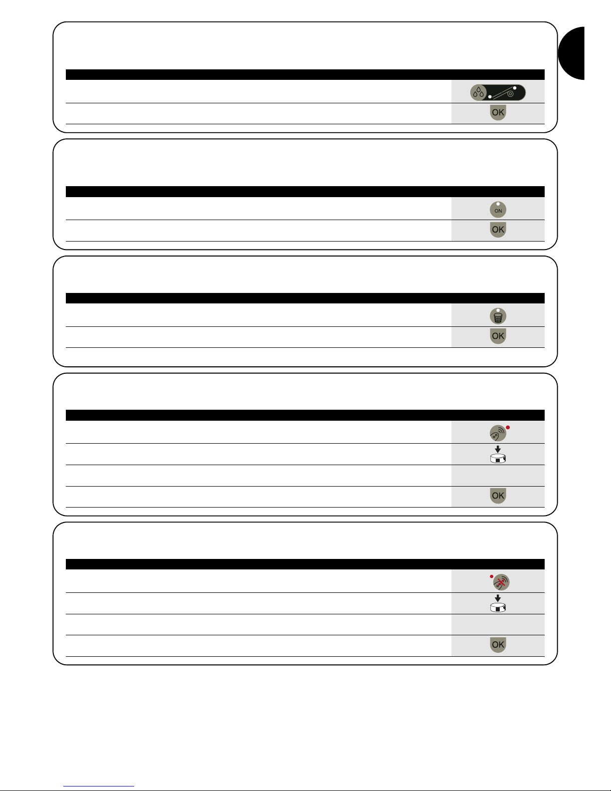
1. Press the ON/OFF key
2. The OK LED starts flashing slowly.
3. Wait for the end of the search:
•If the motor is detected, the green OK LED and the LEDs for the functions available
for programming light up
•If the motor is not detected, the unit emits 2 short beeps and only the red OK LED
lights up
Note: you can interrupt the search at any time by pressing the ON/OFF key again.
Table 6 Searching for the motor Example
4.1.3) Searching for the motor
Once the TTP is switched on, if you briefly press the ON/OFF key, the unit starts searching for any motor that may be connected. During the
search (which may last several seconds) the orange OK LED flashes slowly. On completion of the search, if a motor is recognised, the LEDs
for the functions available for programming light up. If no motor is detected, the error is indicated by an acoustic signal.
1. Press ; the motor starts the UP manoeuvre.
2. Press ; the motor stops the manoeuvre.
3. Press ; the motor starts the DOWN manoeuvre.
4. Press and simultaneously; if an intermediate position has been set, the motor will
move to the set position.
Table 7 Movements Example
4.2) Motor movement keys
The , and keys are the equivalent of the keys on the transmitter and perform the functions set out in Table 7.
+
1. If no direction has been programmed, the and keys do not control motor movements
and the LEDs above the and keys flash simultaneously at very brief, regular intervals.
2. Press the key for the direction you want.
3. The green OK LED starts flashing: press OK within 3 seconds to confirm.
3s
4. On completion of the operation, the LED on the key corresponding to the direction you
have chosen will light up.
Note: after programming the direction of movement, check that the key on the transmitter does in fact open the shutter or pull up the
awning, and that the key closes the shutter or pulls down the awning.
If the devices do not operate in the direction you want, first cancel the direction and then reprogramme with the opposite direction.
To cancel the direction, proceed as described in Table 9.
Table 8 Programming the direction Example
4.3) Programming the direction of movement
For motors with mechanical limit switch, you can quickly change the direction of movement of the motor by following the procedure described
in Table 8.
or
1. Press the ‘Cancel Direction’ key.
2. The green OK LED starts flashing: press OK within 3 seconds to confirm
3s
3. On completion of the operation, the LEDs above the and keys flash simultaneously
at very brief, regular intervals.
In order to control motor movements after cancelling the direction, it is necessary to repeat the procedure described in Table 8.
Table 9 Cancelling the direction Example
4.4) Programming the positions
On motors with electronic limit switch, functions are available for quick programming of positions 0 , 1 and I . If a position has already
been set, the corresponding LED lights up, otherwise a short flash indicates that it has not yet been programmed.