Nidac Presco PIM 3 Series User manual
1
INTRODUCTION
The Presco™ Interface Module (PIM) can be used to
convert commonly used data formats to Nidac
Presco™, RS232, Clock & Data or Wiegand format
data.
FEATURES
•Converts from Wiegand, RS232, Nidac Presco™,
Clock & Data (Magnetic Card) or Dallas iButton™
(commonly referred to as Silicon Key) format.
•Converts to Nidac Presco™, RS232, Clock & Data
(Magnetic Card) or Wiegand format.
•Can convert to or from Wiegand with up to 64 bits
of data, including up to 32 bit site code plus
optional start and end parity bits.
•User programmable site code when converting to
Wiegand.
•Reads up to 64 bits from Dallas iButton™ user
memory or 56 bits from factory ID.
•Reads up to 32 characters or digits from Track 1, 2
or 3 Clock & Data (magnetic card) format input.
•User programmable settings using standard
Presco™ keypad or via RS232 link (software for
RS232 programming is available from Nidac’s
website www.nidac.com).
•Compatible with all current Nidac Presco™
encoders and decoders.
SPECIFICATIONS
Voltage: 10 to 15 Volts D.C.
Current: 30mA max (plus 5V
output draw).
Dimensions: 66mm x 67mm x
23mm.
Weight: 45gms.
Wiegand Pulse Width: 50s
Pulse Separation: 2ms
RS232: Baud Rate: 300, 600, 1200, 2400,
4800, 9600, 19200,
38400, 57600 or
115200 bps.
Data bits: 8
Parity: None, Odd or Even.
Handshaking: Hardware or None.
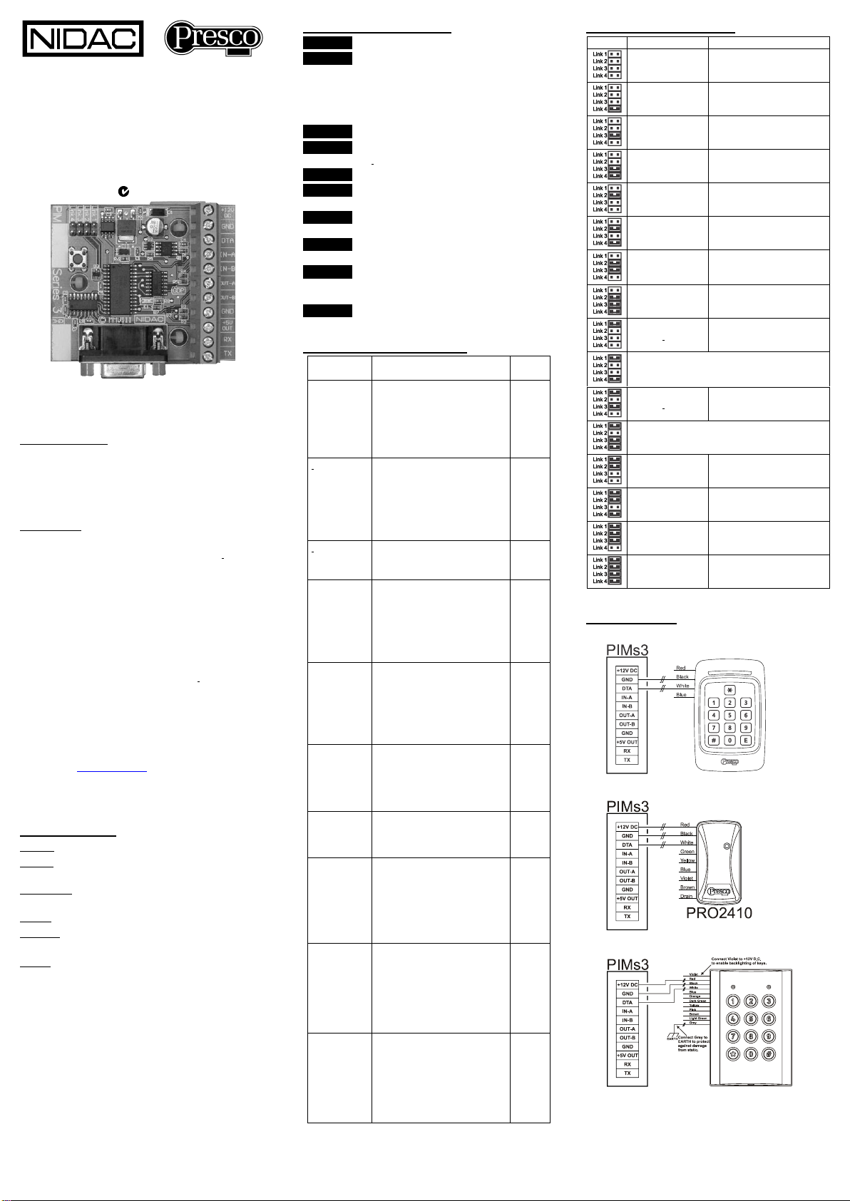
TERMINAL DESCRIPTIONS
+12V DC The positive D.C. power input.
GND The Ground (or Negative) power input.
This is also a common reference
connection for all devices connected to
the PIM. i.e. all devices connected to the
PIM require their GNDs to be connected
together.
DTA Presco™ data input/output.
IN-A Input A (Wiegand D0, Clock & Data RDP
or iButton™).
IN-B Input B (Wiegand D1 or Clock & Data RCP).
OUT-A Output A (Wiegand D0 or Clock & Data
RDP).
OUT-B Output B (Wiegand D1 or Clock & Data
RCP).
+5V OUT A 5 Volt D.C. power output for powering
connected equipment (100mA. max.).
RX The RS232 Receive input (DO NOT USE
THIS TERMINAL WHEN USING THE
RS232 DB9 CONNECTOR!).
TX The RS232 Transmit output.
CABLING DISTANCES TO PIM
Device
Cable type
Max
length
RS232
7/020 shielded or CAT 5
UTP cable.
4 core (3 wires) required for
no handshaking.
6 core (5 wires) required for
hardware handshaking.
10m
iButton™
Telephone cable
Must be unshielded twisted
pair.
2 core for reader only.
4 core for reader + LED
control.
10m
iButton™
CAT 5 cable.
Use 1 pair for reader, any
other wires for LED control.
100m
Clock &
Data
7/020 shielded cable.
4 core for reader only.
6 core for reader + LED
control.
Ground the shield at PIM end
only.
100m
Wiegand
7/020 shielded cable.
4 core for reader only.
6 core for reader + LED
control.
Ground the shield at PIM end
only.
100m
Presco™
PSC16 or
PRE keypad
7/020 unshielded cable.
2 core (figure 8) for data
only, no LED control.
4 core for PSK16/PRE with
LED control.
1000m
Presco™
PSE keypad
without
backlighting
2 core (figure 8) 7/020
unshielded cable.
1000m
Presco™
PSE keypad
with
backlighting
4 core 7/020 unshielded
cable.
NOTE decreased distance is
due to extra current drawn by
backlighting.
4 core 14/020 unshielded
cable.
500m
1000m
Presco™
PRO2410,
PSC16 or
PSR16
proximity
reader
4 core 7/020 unshielded
cable.
4 core 14/020 unshielded
cable.
NOTE decreased distance is
due to extra current drawn by
powering the reader.
350m
800m
Presco™
VR43 or
VR62
keypad.
4 core 7/020 unshielded
cable.
4 core 14/020 unshielded
cable.
NOTE decreased distance is
due to extra current drawn by
powering the keypad.
350m
800m
NOTE all distances are based on a supply voltage of
12.0V D.C. at the PIM.
LINK SETTINGS SUMMARY
Links
Input
Output
Clock & Data
Presco™ (PAC1/PAC2),
Wiegand and RS232
RS232
Clock & Data
Clock & Data
Presco™ (KCx or PDA),
Clock & Data and RS232
Presco™
Clock & Data
RS232
Presco™
Presco™ DLOG
(from PACDL)
RS232
RS232
Presco™ DLOG
(to PAC1 or PAC2 for use
with PIM-PAC software)
Presco™
RS232
Dallas iButton™
Presco™ (PAC1/PAC2),
Wiegand and RS232
Use this setting to reset the memories
to defaults when unit is powered up with
program button depressed.
Dallas iButton™
Presco™ (KCx or PDA),
Clock & Data and RS232
DO NOT USE. Reserved for future use.
Wiegand
Presco™ (PAC1/PAC2),
Wiegand and RS232
RS232
Wiegand
Wiegand
Presco™ (KCx or PDA),
Clock & Data and RS232
Presco™
Wiegand
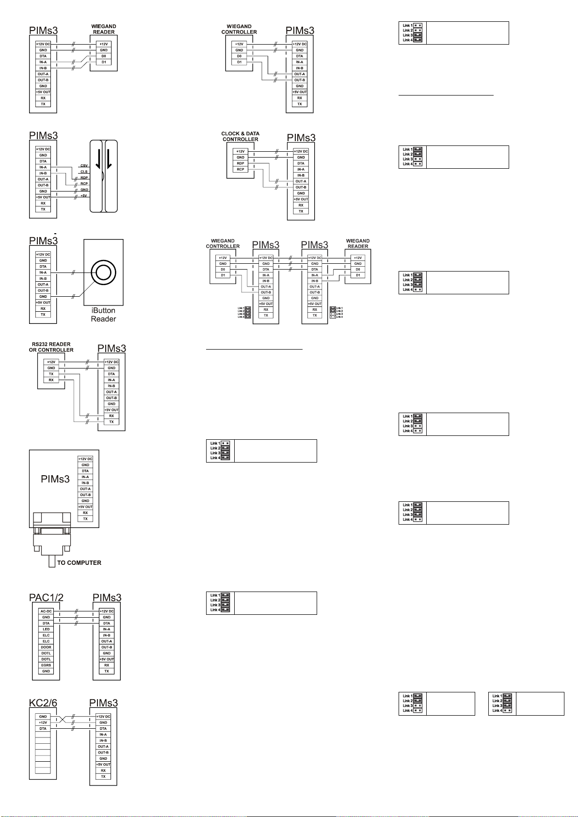
Wiring Diagrams
From Presco™ PSK16 (shown) or PRE
From Presco™ PRO2410 (shown), PSC16 or PSR16
From Presco™ VR43 (shown) or VR62
PIM
Presco™ Interface Module
“Series 3”
Revision h
Installation Manual 1st Edition
N761
2
From Wiegand Reader
From Clock & Data Reader
From Dallas iButton™Reader
From RS232 reader or to RS232 input controller
To or from RS232 computer port
To Presco™ PAC1 or PAC2 Controller
(not for using with PIM-PAC software)
To Presco™ KC2, KC6 or PDA Controller
To Wiegand Input Controller
To Clock & Data Input Controller
Wiegand Extender Wiring
Setmemory 023 to1 on both PIMs for this configuration.
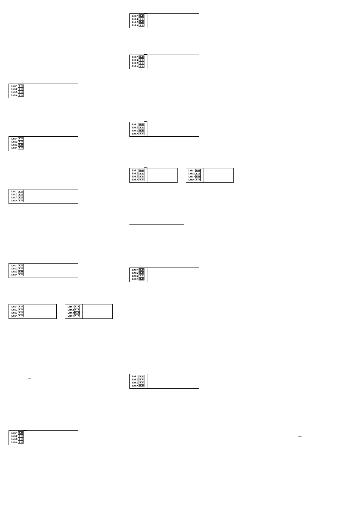
Converting from Presco™
The PIM can read information from any of the Presco™
encoders, including PSK16, PSC16, PRE, VR43, VR62
& PSE keypads and PSR16, PRO2410, Sprite & PRX
Proximity readers.
Note that no information is sent from a Presco™
keypad until the Ekey is pressed (use #on keypads
that don’t have an Ekey).
It can then convert the information to Wiegand, Clock &
Data or RS232.
Presco™ to RS232
Links 2, 3 & 4 ON
Once the data has been entered at a Presco™ encoder
(code then Eor#pressed on keypad orcard presented
at reader) it will be sent to theRS232 port.
The PIM can then optionally make the encoder respond
with a noise as set by the good return character in
memory 021. The default setting is to make the
encoder respond with a single beep.
Data sent to the RS232 port can be either filtered (only
the code digits are sent) or unfiltered (preamble
characters, code and enter character are sent). The
default setting is to filter the data.
Further settings are available for RS232 data. Please
refer to the RS232 SETTINGS MEMORIES section.
Presco™ to Wiegand
All Links ON
The Presco™ data can be converted to either standard
wiegand or burst mode wiegand. There are several
settings for both these modes that can be set, please
refer to the WIEGAND TRANSMIT SETTINGS
MEMORIES section.
In standard mode the code entered from the keypad will
become the user code of the wiegand data and the site
code will be taken from memories 125 to 128.
When converting to standard 26 bit wiegand from a
Presco™ Proximity the PIM will produce the same site
and user codes as if the Wiegand output from the
reader had been used. This is useful if wanting to cable
a Wiegand system further than 100m from reader to
controller. If converting to a Wiegand format other than
standard 26 bit, the result is undefined.
The PIM automatically makes the Presco™ device
respond with the noise as set in memories 021 and 022
for good and bad inputs respectively (a bad input is
when a number too large to convert to the user code is
entered from a keypad).
Presco™ to Clock & Data
Links 3 & 4 ON
The Presco™ data can be converted to 1 to 32 digits of
track 1, 2 or 3 format Clock & Data. Please refer to the
CLOCK & DATA TRANSMIT SETTINGS MEMORIES
section for these settings.
Converting from Wiegand
The PIM can read up to 64 bits of Wiegand data with or
without start and/or end parity bits. It also allows for a
site code of up to 32 bits. The default settings are for
the PIM to read standard 26 bit wiegand.
Wiegand to PRESCO™ for PAC1 or PAC2
Links 1 & 2 ON
The PIM creates an 8 digit number from the Wiegand
data. When receiving 26 bit wiegand it converts the site
code to a 3 digit decimal number, then it converts the
user code to a 5 digit decimal number and combines
these to create the 8 digit code.
eg. Site Code = 183, User Code = 02845
PIM code = 18302845
this is the number to program into the PAC1 or 2.
Optionally the site code portion can be discarded by
setting memory 105 to 0 so that a 5 digit code is sent.
Wiegand to PRESCO™ for PDA, KC2 or KC6
Links 1, 2 & 3 ON
The PIM creates a 7 digit number from the Wiegand
data. When receiving 26 bit wiegand it converts the site
code to a 3 digit decimal number and takes the lowest
2 digits then it converts the user code to a 5 digit
decimal number and combines these to create the 7
digit code.
eg. Site Code = 183, User Code = 02845
PIM code = 8302845
this is the number to program into the PDA, KC2
or KC6.
Optionally the site code portion can be discarded by
setting memory 105 to 0 so that a 5 digit code is sent.
Wiegand to Wiegand
Links 1 & 2 ON
The PIM can be used to convert from one format of
wiegand to another or, by setting memory 105 to 0, it
can be used to replace the site of the received wiegand
and retransmit in the same format (or another) but with
the site code that is stored in the PIM in memories 125
to 128.
Wiegand to Clock & Data
Links 1, 2 & 3 ON
The PIM creates code from the Wiegand data that
consists of the site code (converted to decimal) then the
user code (converted to decimal). It then combines
these 2 together and transmits the last n digits of the
code, where n is the value set in memory 080. When
receiving 26 bit wiegand it converts the site code to a 3
digit decimal number, then it converts the user code to
a 5 digit decimal number and combines these to create
an 8 digit code.
eg. Site Code = 183, User Code = 02845
Memory 080 = 8
Clock & Data code = 18302845
Optionally the site code portion can be discarded by
setting memory 105 to 0 so that the clock & data code
in the example above becomes 00002845.
If value set in memory 080 is more than the number of
digits created by the code conversion leading 0s will be
sent to make up the number.
Wiegand to RS232
Links 1 & 2
ON
or
Links 1,
2 & 3 ON
The data can be sent to the RS232 port as either raw
binary data, ASCII encoded decimal or ASCII encoded
Hexadecimal (see memory 007). The site and user
codes are converted and sent as separate numbers
with the site code being sent first. The default setting is
to send the data as ASCII encoded decimal.
Further settings are available for RS232 data. Please
refer to the RS232 SETTINGS MEMORIES section.
3
Converting from Clock & Data
When reading from a Clock & Data device the PIM
accepts Track 1, 2 or 3 format Clock & Data inputs using
just the RDP and RCP signals.
The PIM reads up to a maximum of 32 characters from
the data stream, though the actual maximum used is
dependent upon the data conversion type.
The PIM can read characters from several different
locations depending upon the settings of memories 062
& 063. The default it setting is to read characters
directly before the first separator character (or end
sentinel if no separator was found).
Clock & Data to PRESCO™ for PAC1 or PAC2
All Links OFF
The PIM reads up to nine (9) digits from the data
stream.
If reading from track 1 and a non numeric character is
found in the data stream then the PIM will ignore the
card.
Clock & Data to PRESCO™ for PDA, KC2 or KC6
Link 3 ON
The PIM reads up to seven (7) digits from the data
stream.
If reading from track 1 and a non numeric character is
found in the data stream then the PIM will ignore the
card.
Clock & Data to Wiegand
All Links OFF
The PIM reads up to 32 characters from the data
stream.
If reading from track 1 and a non numeric character is
found in the data stream then the PIM will ignore the
card.
The data read from the Clock & Data source is
converted to a binary number. The bits above the
number of bits specified for the Wiegand user code are
then discarded.
Clock & Data to Clock & Data
Link 3 ON
The PIM can be used to convert between Track 1 &
Track 2 or 3 data format and can be used to manipulate
the received data and resend only the required part.
Clock & Data to RS232
All Links
OFF
or
Link 3 ON
The PIM reads up to 32 characters from the data stream
and sends the data to the RS232 ports as ASCII
characters.
Further settings are available for RS232 data. Please
refer to the RS232 SETTINGS MEMORIES section.
Converting from Dallas iButton™
Either the unique factory ID code or the user memory
(selected iButton™s only) can be read.
When reading the factory ID up to 56 bits can be read,
8 bit family code + 48 bit serial number.
Up to 64 bits of user memory can be read.
NOTE: The PIM will not read an iButton™’s memory
that contains all 0s or all 1s for the number of bits being
read.
The default setting is to read 32 bits from the factory ID.
Dallas iButton™ to PRESCO™ for PAC1 or PAC2
Link 1 ON
The PIM reads the number of bits specified and
converts them to a either a decimal or base 12 number
(refer to memory 044). The lowest 9 digits of this
number are sent as the code. The default setting is to
convert to base 12.
Dallas iButton™ to PRESCO™ for PDA, KC2 or KC6
Links 1 & 3 ON
The PIM reads the number of bits specified and
converts them to a decimal number. The lowest 7 digits
of this number are sent as the code.
Dallas iButton™ to Wiegand
Link 1 ON
If the number of bits read from the iButton™ is less than
the number of bits specified for the Wiegand user code
then the user code will be padded with leading zeroes
(0).
If the number of bits read from the iButton™ is more
than the number of bits specified for the Wiegand user
code then the extra bits will be ignored and only the
lower bits will be sent as the Wiegand user code.
Dallas iButton™ to Clock & Data
Links 1 & 3 ON
The PIM reads the number of bits specified and
converts them to a either a decimal number. The lowest
n digits, where n is the value of memory 080, of this
number are sent as the clock & data code.
Dallas iButton™ to RS232
Link 1 ON
or
Links 1 & 3
ON
The data can be sent to the RS232 port as either raw
binary data, ASCII encoded decimal or ASCII encoded
Hexadecimal. The default setting is to send the data as
ASCII encoded decimal.
Converting from RS232
The PIM can convert from RS232 to wiegand, clock &
data, Presco™ or Presco™ DLOG.
Only the wiegand and clock & data conversions are
described here as the Presco™ modes are provided for
use with the Presco™ decoder programming software
available from Nidac.
RS232 to Wiegand
Links 1,2 & 4 ON
When the PIM is set to transmit standard format
wiegand the data sent via the RS232 input needs to be
formatted correctly. First the PIM needs to receive the
start char as specified in memory 004 then the data to
be converted to wiegand (as a decimal number
represented by ASCII coded digits) followed by the end
char as specified in memory 005. If the data contains a
separator char as specified in memory 006 then the
digits after the start but before the separator will be
converted to the site code and the digits after the
separator will be converted to the user code. When no
separator if sent all digits will be converted to the user
code and the site code stored in the PIM will be sent.
When the PIM is set to transmit burst mode wiegand the
PIM will convert each ASCII coded digit received on the
RS232 and transmit it as burst mode.
RS232 to Clock & Data
Link 4 ON
The data sent via the RS232 input needs to be
formatted correctly for the PIM to output Clock & Data.
First the PIM needs to receive the start char as specified
in memory 004 then the characters to be sent as clock
& data followed by the end char as specified in memory
005. If the data contains any separator chars as
specified in memory 006 then these will be converted
to the appropriate separator char for the track type
being transmitted and sent with the other characters.
The PIM will automatically transmit the correct start &
end sentinels for the track type being transmitted as well
as the LRC.
PROGRAMMING PIM SETTINGS
Several settings are available through the use of
memories to set the PIM to receive & transmit data in a
specific manner.
Default values are shown in bold italics where a list is
given and in square brackets [] plus bold italics for
other settings.
Programming of all memories can be done via a
Presco™ keypad connected to the DTA terminal or
through the RS232 port.
NOTE that if you program a memory with a value
outside those specified for it, or you program an unlisted
memory, the functionality of the PIM cannot be
guaranteed.
PROGRAMMING USING A PRESCO™ KEYPAD
1. Disconnect all wires from the DTA terminal (except
the white wire from the Presco™ keypad).
2. Connect the Presco™ keypad’s white wire to DTA
and black wire to GND.
3. Ensure that LINK 4 is ON.
4. Press the program button on the PIM. When the
red LED on the PIM starts flashing the unit is in
program mode.
5. Press *<3 digit memory number> <memory
value> E(press #instead of Eif using a VR43,
VR62 or PSE).
6. Repeat step 3 for each memory to be programmed.
7. Press the Program button again. When the red
LED stops flashing all the new values are saved to
memory.
8. Remember to set the LINK 4 back to how it was
and reconnect all wires to the DTA terminal.
9. To reset all the memories back to factory default
press *987654e(press #instead of
Eif using a VR43, VR62 or PSE).
PROGRAMMING USING THE RS232 PORT & PC
1. Disconnect all wires from the RX terminal.
2. Connect a straight through male to female DB9
cable from the PIM to PC’s COM port. The cable
requires the wires for RX, TX, GND, RTS and CTS,
pins 2, 3, 5, 7 & 8.
3. Run the PIMs3 programming software on the PC.
4. Select the COM port the PIM is attached to.
5. Press the program button on the PIM. When the
red LED on the PIM starts flashing the unit is in
program mode.
6. Use the software to set or change the memory
values.
7. Press the Program button again. When the red
LED stops flashing all the new values are saved to
memory.
8. Exit the software.
9. Disconnect the serial cable, if no longer required.
The software for programming the PIM via RS232 is
available from Nidac’s website www.nidac.com in the
Downloads->Presco->Presco Software section.
RS232 SETTINGS MEMORIES
000 Baud rate: 0 = 300, 1 = 600, 2 = 1200,
3 = 2400, 4 = 4800, 5 = 9600, 6 = 19200,
7 = 38400, 8 = 57600, 9 = 115200.
001 Parity: 0 = Even, 1 = Odd, 2 = None.
002 Handshaking: 0 = None, 1 = Hardware
(RTS/CTS).
003 Send data config: 0 = code only,
1 = code + start char,
2 = code + end char,
3 = code + start & end chars,
4 = code + start, separator & end chars.
If unfiltered data from Presco™ or binary data
from Wiegand or iButton™ is being sent, code
only mode (0) is always used no matter what is
set for this memory.
004 Start data character: Used to indicate the start
of a data sequence [2 = STX].
005 End data character: Used to indicate the end of
a data sequence [3 = ETX].
006 Separator character: Used to indicate the end
of the site code and start of user code for
Wiegand conversion [23 = ETB].

4
007RS232 conversion format (only affects
iButton™& Wiegand reads):
0 = Raw,
1 = Decimal,
2 = Hex,
3 = ASCII encoded Binary.
PRESCO™ SETTINGS MEMORIES
020 To RS232 filter: 0 = No filtering, 1 = Filter off
preamble & enter characters, 2 = Filter +
automatically send a good response char.
021Good response character [69 = 1 beep].
022Bad response character [66 = blarp (long
beep)].
Valid response characters are:
65 = 2 beeps, 66 = blarp, 67 = 5 beeps,
68 = silence, 69 = 1 beep, 70 = warble,
71 = 3x2 blips, 73 = 3 beeps, 74 = 4 beeps,
75 = 2 blips, 76 = 2x2 blips, 77 = ramp up,
78 = ramp down.
023Wiegand conversion mode:
0 = standard,
1 = Wiegand extender mode.
The Wiegand extender mode uses 2 PIMs
between the Wiegand reader and controller to
allow for separation distances of up to 1km. The
PIM closest to the reader reads up to 64 bits of
wiegand data (plus start & end parity), converts
the data to a special Presco™ format and the
second PIM converts it back to the original
Wiegand. There is no need to tell either PIM the
format of the wiegand data.
iButton™ SETTINGS MEMORIES
040 Data bits to read: 0 = Factory ID, 1 = User
memory (LSB stored first).
041Number of bits to read: 8 to 64 [32].
042Memory read address high byte: 0 to 255 [0].
043Memory read address low byte: 0 to 255 [0].
044 Presco™ PAC conversion format: 0 = Decimal,
1 = Base 12.
CLOCK & DATA RECEIVE SETTINGS MEMORIES
060 Number of characters to read: 1 to 32 [8].
061Data type: 0 = Track 1, 1 = Track 2/Track 3.
062Read from start or end:
0 = Read from start,
1 = Read from end,
2 = Read from start after separator,
3 = Read from end after separator.
063 Number of characters to skip from start [0].
When reading from the start or the start after
separator the PIM will skip this number of
characters before reading any data.
CLOCK & DATA TRANSMIT SETTINGS MEMORIES
080 Number of characters to transmit: 1 to 32 [8].
081Data type: 0 = Track 1, 1 = Track 2/Track 3.
WIEGAND RECEIVE SETTINGS MEMORIES
The default memory settings are to receive standard 26
bit wiegand.
100 Number of bits in site code: 0 to 32 [8].
101 Number of bits in user code: 8 to 64 [16].
102 Number of bits for start parity (0 = no start
parity bit, 64 or greater = use half the total
number of data bits) [255].
103 Number of bits for end parity (0 = no end parity
bit, 64 or greater = use half the total number of
data bits) [255].
104 Parity polarity:
0 = Start & End Even,
1 = Start Odd & End Even,
2 = Start Even & End Odd,
3 = Start & End Odd,
4 = Do not check parity.
105 Transmit received site code: [255]
0 = Don’t transmit the received site code,
All other vales = Do transmit.
Note that this memory has no effect when
transmitting RS232 data.
110 Custom total number of receive bits [255].
When this memory is set to 0 the PIM will
ignore all settings in memories 100 to 105 and
111 to 113 and will receive wiegand data until
either is has received 64 bits of data or 8
milliseconds has elapsed since it received its
last data bit. All these bits will be treated as the
user code with no site code data.
When this memory contains a value that
specifies a total number of data bits of between
8 & 64 then the custom wiegand receive mode
is enabled (if start and/or end parity is specified
in memories 102 & 103 then these bits need to
be taken into account when specifying the total
number of bits).
The number of bits for the site & user code are
still as specified in memories 100 & 101 but the
starting position of the site & user codes within
the received bits can be specified via memories
112 & 113.
Note that using this setting requires a high
understanding of Wiegand data. Nidac will only
offer limited support for this feature.
111 Expect LSB first in custom mode: [255]
1 = LSB is received first when in custom mode,
All other values = MSB received first.
112 The bit number within the received data that the
site code data starts at (only used when in
custom receive mode), note that the first bit
received is bit 1. [255]
113The bit number within the received data that the
user code data starts at (only used when in
custom receive mode), note that the first bit
received is bit 1. [255]
WIEGAND TRANSMIT SETTINGS MEMORIES
The default memory settings are to transmit standard
26 bit wiegand.
120 Number of bits in site code: 0 to 32 [8].
121 Number of bits in user code: 8 to 64 [16].
122 Number of bits for start parity (0 = no start
parity bit, 64 or greater = use half the total
number of data bits) [255].
123 Number of bits for end parity (0 = no end parity
bit, 64 or greater = use half the total number of
data bits) [255].
124 Parity polarity:
0 = Start & End Even,
1 = Start Odd & End Even,
2 = Start Even & End Odd,
3 = Start & End Odd.
125 Site code byte 3 (bits 24 to 31): 0 to 255 [0].
126 Site code byte 2 (bits 16 to 23): 0 to 255 [0].
127 Site code byte 1 (bits 8 to 15): 0 to 255 [0].
128 Site code byte 0 (bits 0 to 7): 0 to 255 [1] (used
for standard 8 bit site code, when using 26 bit
Wiegand).
130 Wiegand transmit mode:
0 = standard,
1 = 4 bit burst mode,
2 = 4 bit burst mode ignoring *and #keys,
3 = 8 bit burst mode,
4 = 8 bit burst mode ignoring *and #keys,
5 = 4 bit burst mode and a #at end of code,
6 = 8 bit burst mode and a #at end of code.
In 4 or 8 bit burst mode each digit received is
sent as an individual Wiegand burst character at
a rate determined by memory 131.
Note that when using a Presco™ keypad no
data is sent until the Ekey is pressed (#key
on a VR43, VR62 or PSE).
Note: setting options 5 & 6 are only valid when
converting from Presco™ and are only available
with firmware revision 3d or greater.
131 Burst Mode Delay, the delay between sending
burst mode characters in 0.1 second
increments. [2]
132 Custom total number of transmit bits [255].
When this memory contains a value that
specifies a total number of data bits of between
8 & 64 then the custom wiegand transmit mode
is enabled (if start and/or end parity is specified
in memories 122 & 123 then these bits need to
be taken into account when specifying the total
number of bits).
The number of bits for the site & user code are
still as specified in memories 120 & 121 but the
starting position of the site & user codes within
the transmitted bits can be specified via
memories 134 & 135.
Note that using this setting requires a high
understanding of Wiegand data. Nidac will only
offer limited support for this feature.
133 Send LSB first in custom mode: [255]
1 = LSB is transmitted first when in custom
mode,
All other values = MSB received first.
134 The bit number within the transmitted data that
the site code data starts at (only used when in
custom transmit mode), note that the first bit
transmitted is bit 1. [255]
135 The bit number within the transmitted data that
the user code data starts at (only used when in
custom transmit mode), note that the first bit
transmitted is bit 1. [255]
140 Default custom wiegand pattern byte 7. [255]
141 Default custom wiegand pattern byte 6. [255]
142 Default custom wiegand pattern byte 5. [255]
143 Default custom wiegand pattern byte 4. [255]
144 Default custom wiegand pattern byte 3. [255]
145 Default custom wiegand pattern byte 2. [255]
146 Default custom wiegand pattern byte 1. [255]
147 Default custom wiegand pattern byte 0. [255]
Memories 140 to 147 specify the default pattern to be
used when transmitting in custom wiegand mode (refer
memory 132). These are the bits that will be transmitted
when the data bits (including site, user & parity) are not
being sent.
PAC1/2 Programming Software
Presco™ decoder programming software is also
available to use with the PIM. This software will allow
you to connect a PAC1 or PAC2 to a PIM that is
connected to a PC and program all settings and users
codes. It also allows the extraction of settings and user
codes from existing programmed decoders.
The PAC decoder programming software is available
from Nidac’s website www.nidac.com in the
Downloads->Presco->Presco Software section.
Links 2 & 3 ON
100%
NIDAC SECURITY PTY. LTD.
MANUFACTURERS OF SECURITY EQUIPMENT
A.B.N. 49 004 933 242
2 CROMWELL STREET
BURWOOD, VICTORIA
AUSTRALIA 3125
TEL: +61 3 9808 6244
FAX: +61 3 9808 9335
WEB: www.nidac.com
Revision 3h


