Nidec Unidrive M700 User manual

User Guide
SI-Ethernet and
Unidrive M -
Onboard Ethernet
Part Number: 0478-0137-03
Issue: 3

Original Instructions
For the purposes of compliance with the EU Machinery Directive 2006/42/EC, the English version of this manual
is the Original Instructions. Manuals in other languages are Translations of the Original Instructions.
Documentation
Manuals are available to download from the following locations: http://www.drive-setup.com/ctdownloads
The information contained in this manual is believed to be correct at the time of printing and does not form part of
any contract. The manufacturer reserves the right to change the specification of the product and its performance,
and the contents of the manual, without notice.
Warranty and Liability
In no event and under no circumstances shall the manufacturer be liable for damages and failures due to misuse,
abuse, improper installation, or abnormal conditions of temperature, dust, or corrosion, or failures due to
operation outside the published ratings. The manufacturer is not liable for consequential and incidental damages.
Contact the supplier of the drive for full details of the warranty terms.
Environmental policy
Control Techniques Ltd operates an Environmental Management System (EMS) that conforms to the
International Standard ISO 14001.
Further information on our Environmental Policy can be found at: http://www.drive-setup.com/environment
Restriction of Hazardous Substances (RoHS)
The products covered by this manual comply with European and International regulations on the Restriction of Haz-
ardous Substances including EU directive 2011/65/EU and the Chinese Administrative Measures for Restriction of
Hazardous Substances in Electrical and Electronic Products.
Disposal and Recycling (WEEE)
REACH legislation
EC Regulation 1907/2006 on the Registration, Evaluation, Authorisation and restriction of Chemicals (REACH)
requires the supplier of an article to inform the recipient if it contains more than a specified proportion of any
substance which is considered by the European Chemicals Agency (ECHA) to be a Substance of Very High
Concern (SVHC) and is therefore listed by them as a candidate for compulsory authorisation.
Further information on our compliance with REACH can be found at: http://www.drive-setup.com/reach
Registered Office
Nidec Control Techniques Ltd
The Gro
Newtown
Powys
SY16 3BE
UK
Registered in England and Wales. Company Reg. No. 01236886.
When electronic products reach the end of their useful life, they must not be disposed of along
with domestic waste but should be recycled by a specialist recycler of electronic equipment.
Control Techniques products are designed to be easily dismantled into their major component
parts for efficient recycling. The majority of materials used in the product are suitable for
recycling.
Product packaging is of good quality and can be re-used. Large products are packed in wooden
crates. Smaller products are packaged in strong cardboard cartons which have a high recycled
fibre content. Cartons can be re-used and recycled. Polythene, used in protective film and bags
for wrapping the product, can be recycled. When preparing to recycle or dispose of any product
or packaging, please observe local legislation and best practice.

Copyright
The contents of this publication are believed to be correct at the time of printing. In the interests of a commitment
to a policy of continuous development and improvement, the manufacturer reserves the right to change the
specification of the product or its performance, or the contents of the guide, without notice.
All rights reserved. No parts of this guide may be reproduced or transmitted in any form or by any means,
electrical or mechanical including photocopying, recording or by an information storage or retrieval system,
without permission in writing from the publisher.
Copyright © January 2018 Nidec Control Techniques Ltd

4SI-Ethernet User Guide
Issue Number: 3
Contents
1 Safety information ..........................................................6
1.1 Warnings, cautions and notes .................................................................6
1.2 Important safety information. Hazards.
Competence of designers and installers .................................................6
1.3 Responsibility ..........................................................................................6
1.4 Compliance with regulations ...................................................................6
1.5 Electrical hazards ....................................................................................7
1.6 Stored electrical charge ...........................................................................7
1.7 Mechanical hazards ................................................................................7
1.8 Access to equipment ...............................................................................7
1.9 Environmental limits ................................................................................7
1.10 Hazardous environments ........................................................................8
1.11 Motor .......................................................................................................8
1.12 Mechanical brake control ........................................................................8
1.13 Adjusting parameters ..............................................................................8
1.14 Electromagnetic compatibility (EMC) ......................................................8
2 Introduction ....................................................................9
2.1 Products covered by this User Guide ......................................................9
2.2 Features ..................................................................................................9
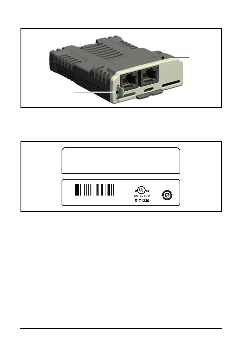
2.3 Option module identification ..................................................................10
2.4 Factory fit Ethernet interface identification ............................................11
2.5 Product conformance ............................................................................11
2.6 Conventions used in this guide .............................................................11
2.7 Firmware Statement ..............................................................................11
3 Mechanical installation ................................................12
4 Electrical installation ...................................................14
4.1 SI-Ethernet module information .............................................................14
4.2 Cabling considerations ..........................................................................14
4.3 Module grounding ..................................................................................14
4.4 Cable shield connections ......................................................................15
4.5 Cable .....................................................................................................15
4.6 Maximum network length ......................................................................15
4.7 Network topology ...................................................................................15
5 Getting started ..............................................................17
5.1 Network design considerations .............................................................17
5.2 Addressing ............................................................................................17
5.3 Where do IP addresses come from? .....................................................17
5.4 Addressing etiquette ..............................................................................17
5.5 Class types ............................................................................................18
5.6 Generating the complete address .........................................................18
5.7 DHCP considerations ............................................................................19
5.8 Basic principles of routing .....................................................................20
5.9 Set-up flow chart ...................................................................................21
5.10 Single line parameter descriptions ........................................................22

SI-Ethernet User Guide 5
Issue Number: 3
6 Parameters ....................................................................36
6.1 Full parameter descriptions ...................................................................36
7 Key features and Protocols .......................................135
7.1 PC/PLC considerations .......................................................................135
7.2 Modbus TCP/IP ...................................................................................135
7.3 RTMoE (Real Time Motion over Ethernet) ..........................................144
7.4 Non-cyclic data access ........................................................................153
7.5 EtherNet/IP ..........................................................................................158
7.6 Web page basics .................................................................................191
8 PC Tools Applications ...............................................198
8.1 Unidrive M Connect .............................................................................198
8.2 Machine Control Studio .......................................................................198
8.3 CTScope .............................................................................................199
8.4 SyPTPro ..............................................................................................199
8.5 CT OPC server ....................................................................................200
9 Security .......................................................................201
9.1 Introduction ..........................................................................................201
9.2 General site security issues ................................................................201
9.3 Default restrictions ...............................................................................201
10 Diagnostics .................................................................202
10.1 LED diagnostics ..................................................................................202
10.2 Drive trip display codes .......................................................................202
10.3 Ethernet sub trip codes .......................................................................203
10.4 Ethernet sub trip codes .......................................................................205
10.5 Ethernet hardware fault trip codes ......................................................205
10.6 Diagnostic flow chart ...........................................................................206
11 Glossary of terms .......................................................207

6SI-Ethernet User Guide
Issue: 3
1 Safety information
1.1 Warnings, cautions and notes
1.2 Important safety information. Hazards. Competence of
designers and installers
This guide applies to products which control electric motors either directly (drives) or indirectly
(controllers, option modules and other auxiliary equipment and accessories). In all cases the
hazards associated with powerful electrical drives are present, and all safety information relating to
drives and associated equipment must be observed.
Specific warnings are given at the relevant places in this guide.
Drives and controllers are intended as components for professional incorporation into complete
systems. If installed incorrectly they may present a safety hazard. The drive uses high voltages and
currents, carries a high level of stored electrical energy, and is used to control equipment which can
cause injury. Close attention is required to the electrical installation and the system design to avoid
hazards either in normal operation or in the event of equipment malfunction. System design,
installation, commissioning/start-up and maintenance must be carried out by personnel who have
the necessary training and competence. They must read this safety information and this guide
carefully.
1.3 Responsibility
It is the responsibility of the installer to ensure that the equipment is installed correctly with regard
to all instructions given in this guide. They must give due consideration to the safety of the complete
system, so as to avoid the risk of injury both in normal operation and in the event of a fault or of
reasonably foreseeable misuse.
The manufacturer accepts no liability for any consequences resulting from inappropriate, negligent
or incorrect installation of the equipment.
1.4 Compliance with regulations
The installer is responsible for complying with all relevant regulations, such as national wiring
regulations, accident prevention regulations and electromagnetic compatibility (EMC) regulations.
Particular attention must be given to the cross-sectional areas of conductors, the selection of fuses
or other protection, and protective ground (earth) connections.
This guide contains instructions for achieving compliance with specific EMC standards.
All machinery to be supplied within the European Union in which this product is used must comply
with the following directives:
2006/42/EC Safety of machinery.
2014/30/EU: Electromagnetic Compatibility.
A Warning contains information, which is essential for avoiding a safety hazard.
A Caution contains information, which is necessary for avoiding a risk of damage to the
product or other equipment.
A Note contains information, which helps to ensure correct operation of the product.
WARNING
CAUT IO N
NOTE

SI-Ethernet User Guide 7
Issue: 3
Safety
information Introduction Mechanical
installation
Electrical
installation Getting started Parameters Key features and
Protocols
PC Tools
Applications Security Diagnostics Glossary of
terms Index
1.5 Electrical hazards
The voltages used in the drive can cause severe electrical shock and/or burns, and could be lethal.
Extreme care is necessary at all times when working with or adjacent to the drive. Hazardous
voltage may be present in any of the following locations:
• AC and DC supply cables and connections
• Output cables and connections
• Many internal parts of the drive, and external option units
Unless otherwise indicated, control terminals are single insulated and must not be touched.
The supply must be disconnected by an approved electrical isolation device before gaining access
to the electrical connections.
The STOP and Safe Torque Off functions of the drive do not isolate dangerous voltages from the
output of the drive or from any external option unit.
The drive must be installed in accordance with the instructions given in this guide. Failure to
observe the instructions could result in a fire hazard.
1.6 Stored electrical charge
The drive contains capacitors that remain charged to a potentially lethal voltage after the AC supply
has been disconnected. If the drive has been energized, the AC supply must be isolated at least
ten minutes before work may continue.
1.7 Mechanical hazards
Careful consideration must be given to the functions of the drive or controller which might result in a
hazard, either through their intended behaviour or through incorrect operation due to a fault. In any
application where a malfunction of the drive or its control system could lead to or allow damage,
loss or injury, a risk analysis must be carried out, and where necessary, further measures taken to
reduce the risk - for example, an over-speed protection device in case of failure of the speed
control, or a fail-safe mechanical brake in case of loss of motor braking.
With the sole exception of the Safe Torque Off function, none of the drive functions must be
used to ensure safety of personnel, i.e. they must not be used for safety-related functions.
The Safe Torque Off function may be used in a safety-related application. The system designer is
responsible for ensuring that the complete system is safe and designed correctly according to the
relevant safety standards.
The design of safety-related control systems must only be done by personnel with the required
training and experience. The Safe Torque Off function will only ensure the safety of a machine if it is
correctly incorporated into a complete safety system. The system must be subject to a risk
assessment to confirm that the residual risk of an unsafe event is at an acceptable level for the
application.
1.8 Access to equipment
Access must be restricted to authorized personnel only. Safety regulations which apply at the place
of use must be complied with.
1.9 Environmental limits
Instructions in this guide regarding transport, storage, installation and use of the equipment must
be complied with, including the specified environmental limits. This includes temperature, humidity,
contamination, shock and vibration. Drives must not be subjected to excessive physical force.

8SI-Ethernet User Guide
Issue: 3
1.10 Hazardous environments
The equipment must not be installed in a hazardous environment (i.e. a potentially explosive
environment).
1.11 Motor
The safety of the motor under variable speed conditions must be ensured.
To avoid the risk of physical injury, do not exceed the maximum specified speed of the motor.
Low speeds may cause the motor to overheat because the cooling fan becomes less effective,
causing a fire hazard. The motor should be installed with a protection thermistor. If necessary, an
electric forced vent fan should be used.
The values of the motor parameters set in the drive affect the protection of the motor. The default
values in the drive must not be relied upon. It is essential that the correct value is entered in the
Motor Rated Current parameter.
1.12 Mechanical brake control
Any brake control functions are provided to allow well co-ordinated operation of an external brake
with the drive. While both hardware and software are designed to high standards of quality and
robustness, they are not intended for use as safety functions, i.e. where a fault or failure would
result in a risk of injury. In any application where the incorrect operation of the brake release
mechanism could result in injury, independent protection devices of proven integrity must also be
incorporated.
1.13 Adjusting parameters
Some parameters have a profound effect on the operation of the drive. They must not be altered
without careful consideration of the impact on the controlled system. Measures must be taken to
prevent unwanted changes due to error or tampering.
1.14 Electromagnetic compatibility (EMC)
Installation instructions for a range of EMC environments are provided in the relevant Power
Installation Guide. If the installation is poorly designed or other equipment does not comply with
suitable standards for EMC, the product might cause or suffer from disturbance due to
electromagnetic interaction with other equipment. It is the responsibility of the installer to ensure
that the equipment or system into which the product is incorporated complies with the relevant EMC
legislation in the place of use.

SI-Ethernet User Guide 9
Issue: 3
Safety
information
Introduction
Mechanical
installation
Electrical
installation Getting started Parameters Key features and
Protocols
PC Tools
Applications Security Diagnostics Glossary of
terms Index
2 Introduction
2.1 Products covered by this User Guide
This User Guide covers the SI-Ethernet option module and the onboard factory installed Ethernet
interface. Both the SI-Ethernet module and the onboard Ethernet interface offer the same
functionality.
The onboard Ethernet interface provides Ethernet connectivity and is installed during manufacture
to the following drives:
• Unidrive M700
• Unidrive M702
The SI-Ethernet is an option module that provides Ethernet connectivity and can be installed to the
following drives:
• Unidrive M200 / M201 (sizes 2 to 9)
• Unidrive M300 (sizes 2 to 9)
• Unidrive M400 (sizes 2 to 9)
• Unidrive M600 (sizes 3 to 11)
• Unidrive M700 / M701 / M702 (sizes 3 to 11)
2.2 Features
The following list gives an overview of the functionality available:
• Single RJ45 connectivity with support for shielded twisted pair.
• 100 Mbs Ethernet with auto-negotiation.
• Full and half duplex operation with auto-negotiation.
• Auto crossover detection.
• TCP/IP.
• Modbus TCP/IP.
• EtherNet/IP.
• Switch or Gateway mode.
• VLAN tagging.
• SyPTPro over Ethernet.
• Unidrive M Connect over Ethernet.
• Machine Control Studio.
• Static IP configuration or DHCP client.
• Non-cyclic data transfer with user program.
• Up to 3 transmit and 3 receive cyclic links (easy mode).
• IEEE1588 Precision Time Protocol synchronization.
• RTMoE (Real Time Motion over Ethernet).
2.2.1 Backup/auxiliary supply
Some drives provide a method of powering up the control circuits (and therefore any option module
installed) if the AC supply is removed, this allows Ethernet communication to continue operating
when the main AC supply is switched off.

10 SI-Ethernet User Guide
Issue: 3
2.3 Option module identification
Figure 2-1 SI-Ethernet
The SI-Ethernet can be identified by:
1. The label located on the topside of the option module.
2. The color coding across the front of the option module. SI-Ethernet being beige.
Figure 2-2 SI-Ethernet label
2.3.1 Date code format
The date code is four numbers. The first two numbers indicate the year and the remaining numbers
indicate the week of the year in which the drive was built.
Example:
A date code of 1710 would correspond to week 10 of year 2017.
Earth
connection
Link
LEDs
SI-Ethernet
1714
S/N : 8000001001
S/N : 8000001001
82400000017900

SI-Ethernet User Guide 11
Issue: 3
Safety
information
Introduction
Mechanical
installation
Electrical
installation Getting started Parameters Key features and
Protocols
PC Tools
Applications Security Diagnostics Glossary of
terms Index
2.4 Factory fit Ethernet interface identification
As standard, the Unidrive M700 and Unidrive M702 variants are fitted with an Ethernet interface
and the Unidrive M701 is fitted with the EIA-485 serial communications interface.
Care must be taken to ensure the correct interface is fitted before a connection is made to the drive,
failure to ensure this may result in damage to the interface and/or communication device.
The Ethernet and EIA 485 interfaces are similar in appearance but the differences are:
• The Ethernet interface will have the Ethernet communication logo on the front of the
panel with the appropriate port number below it. It also has a LED located below each
connector.
• The EIA 485 port just has the number "485" printed alongside it.
2.5 Product conformance
The Ethernet interface complies with IEEE 802.3 and meets the isolation requirements of safety
standard EN50178:1998.
2.6 Conventions used in this guide
The configuration of the host drive and option module is done using menus and parameters. A
menu is a logical collection of parameters that have similar functionality.
In the case of an option module, the option module set-up parameters in menu 0 will appear in
drive menu 15, 16 or 17 depending on which slot the module is installed in. In the case of the
onboard Ethernet interface, the set-up parameters in menu 0 will appear in drive menu 24.
The setting of the Option Slot Identifiers (Pr 11.056) may change the slot numbering from those
described above. The internal menus of the option module or onboard Ethernet interface will
appear before menu 0 and after menu 41.
The method used to determine the menu or parameter is as follows:
•PrS.mm.ppp - Where Ssignifies the option module slot number and mm.ppp signifies the
menu and parameter number respectively.
If the option module slot number is not specified then the parameter reference will be a drive
parameter.
•PrMM.ppp - Where MM signifies the menu allocated to the option module setup menu and
ppp signifies the parameter number within the set-up menu.
•Prmm.000 - Signifies parameter number 000 in any drive menu.
2.7 Firmware Statement
This product is supplied with the latest firmware version. When retro-fitting to an existing system, all
firmware versions should be verified to confirm the same functionality as products of the same type
already present. This also applies to products returned from a Nidec Industrial Automation’s
Service Centre or Repair Centre. If there is any doubt please contact the supplier of the product.
The firmware version of the product can be identified by looking at Pr MM.002 where MM is the
relevant menu number for the module slot being used.
For Unidrive M200, M300 and M400 drives, the option module set-up parameters will
appear in menu 15.
NOTE

12 SI-Ethernet User Guide
Issue: 3
3 Mechanical installation
Figure 3-1 Installation of an SI option module on Unidrive M200 to M400 (sizes 2 to 4)
• With the option module tilted slightly backwards, align and locate the two holes in the rear of the
option module onto the two tabs (1) on the drive.
• Place the option module onto the drive as shown in (2) until the module clicks into place. The
terminal cover on the drive holds the option module in place, so this must be put back on.
Before installing or removing an option module from any drive, ensure the AC supply has
been disconnected for at least 10 minutes and refer to Chapter 1 Safety information on
page 6. If using a DC bus supply ensure this is fully discharged before working on any
drive or option module.
WARNING
1
2
Option modules can only be installed on drives that have the option module slot
functionality.
Figure 3-1 above is for illustration only, the actual option module may be different to the
one shown.
NOTE
NOTE

SI-Ethernet User Guide 13
Issue: 3
Safety
information Introduction Mechanical
installation
Electrical
installation Getting started Parameters Key features
and Protocols
PC Tools
Applications Security Diagnostics Glossary of
terms Index
Figure 3-2 Installation of an SI option module on Unidrive M200 to M400 (sizes 5 to 9)
• Place the option module onto the drive as shown in (2) until the module clicks into place. The
terminal cover on the drive holds the option module in place, so this must be put back on.
Figure 3-3 Installation of an SI option module on Unidrive M600 to M702
• Move the option module in direction shown (1/2).
• Align and insert the option module tab in to the slot provided, this is highlighted in the detailed
view (A).
• Press down on the option module until it clicks into place.
1
2
2
Option module slots must be used in the following order: Slot 3 (lower), Slot 2 (middle)
and then Slot 1(upper).
NOTE

14 SI-Ethernet User Guide
Issue: 3
4 Electrical installation
4.1 SI-Ethernet module information
SI-Ethernet provides two standard RJ45 UTP/STP (Un-shielded/Shielded Twisted Pair)
connections to a 100 Mbs Ethernet system. In addition to the RJ45 connectors, a grounding tag is
supplied for supplementary bonding. SI-Ethernet provides 2 diagnostic LEDs for status and
information purposes located on the module topside.
Figure 4-1 SI-Ethernet
Figure 4-1 shows an overview of the module connections and indicators.
Figure 4-2 Ethernet connections
Figure 4-2 shows the electrical connections of the RJ45 connector.
4.2 Cabling considerations
To ensure long-term reliability it is recommended that any cables used to connect a system
together are tested using a suitable Ethernet cable tester, this is of particular importance when
cables are constructed on site.
Any isolated signal circuit has the capability to become live through accidental contact with other
conductors; as such they should always be double-insulated from live parts. The routing of network
and signal wires should be done so as to avoid close proximity to mains voltage cabling.
4.3 Module grounding
SI-Ethernet is supplied with a grounding tag on the module that should be connected to the closest
possible grounding point using the minimum length of cable. This will greatly improve the noise
immunity of the module.
On the onboard Ethernet interface, pin1 is located on the left but on the SI-Ethernet
module pin 1 is located on the right (as shown).
Earth
connection
Link
LEDs
Not used
12345678
Not used
Transmit +
Receive +
Not used
Transmit -
Receive -
Not used
Not used
12345678
Not used
Transmit +
Receive +
Not used
Transmit -
Receive -
Not used
Spade
connector
NOTE

SI-Ethernet User Guide 15
Issue: 3
Safety
information Introduction Mechanical
installation
Electrical
installation
Getting started Parameters Key features
and Protocols
PC Tools
Applications Security Diagnostics Glossary of
terms Index
4.4 Cable shield connections
Standard Ethernet UTP or STP cables do not require supplementary grounding.
4.5 Cable
It is recommended that a minimum specification of CAT5e is installed on new installations, as this
gives a good cost/performance ratio. If you are using existing cabling, this may limit the maximum
data rate depending on the cable ratings. In noisy environments, the use of STP or fiber optic cable
will offer additional noise immunity.
4.6 Maximum network length
The main restriction imposed on Ethernet cabling is the length of a single segment of cable as
detailed in Table 4-1. If distances greater than this are required it may be possible to extend the
network with additional switches or by using a fiber optic converter.
4.7 Network topology
The SI-Ethernet option module and onboard Ethernet interface support multiple network topologies
this allows the user to design a robust network using the topology that works best for the chosen
design.
Star topology:
• Enables individual devices to be swapped out
• Minimise message transmission delays
Line topology (daisy chain):
• Simple wiring
• Lowest cost
Tree topology:
• Maximises bandwidth - contains messages within appropriate segments
• Products can be connected in functional groups, e.g. to enable one section of a machine to be
turned off
Cabling issues are the single biggest cause of network down-time. Ensure cabling is
correctly routed, wiring is correct, connectors are correctly installed and any switches or
routers used are rated for industrial use. Office grade Ethernet equipment does not
generally offer the same degree of noise immunity as equipment intended for industrial
use.
Table 4-1 Ethernet maximum network lengths
Type Of Cable Data rate (bit/s) Maximum trunk length (m)
Copper - UTP/STP CAT 5
100 M
100
Fiber Optic - Multi-mode 3000
Fiber Optic - Single-mode up to 100000
The distances specified are absolute recommended maximums for reliable transmission
of data. The distances for the fiber optic sections will be dependent on the equipment
used on the network. The use of wireless networking products is not recommended for
control systems, as performance may be affected by many external influences.
NOTE
NOTE

16 SI-Ethernet User Guide
Issue: 3
Figure 4-3 Typical network topologies

SI-Ethernet User Guide 17
Issue: 3
Safety
information Introduction Mechanical
installation
Electrical
installation
Getting started
Parameters Key features
and Protocols
PC Tools
Applications Security Diagnostics Glossary of
terms Index
5 Getting started
5.1 Network design considerations
Ethernet is an open system allowing many different vendors to design and supply equipment.
When designing an industrial network you must carefully consider the topology and data traffic on
the network to avoid potential problems.
To avoid bandwidth issues it is recommended that the control network is logically separate from any
other network. Where possible a physically separate network should be used. If this is not possible,
the use of managed network devices should be considered to prevent unnecessary traffic such as
broadcasts reaching the control network.
5.2 Addressing
The addressing system used on Ethernet uses two essential numbers for making connection, these
are the IP address and the subnet mask. The address allows a specific device to be located and
the subnet mask defines how many bits represent the subnet part of the address and how many
bits represent the node address (see section 5.6.1 The IP address on page 19). Generally devices
on different subnets can only communicate by using a gateway (typically a router or firewall).
5.3 Where do IP addresses come from?
Every address on a network must be unique. If you do not connect your network to any other
networks the assignment of IP addresses is not critical (although using a standard system is
recommended), as you have full control of the addresses used. The issue of addressing becomes
important when connecting multiple networks together or connecting to the Internet where there is
a strong possibility of duplication of addresses if a scheme is not followed.
5.4 Addressing etiquette
The following list details some points that should be considered when selecting addresses:
•Reserve address space: Ensure you have enough reserve address space on your chosen
addressing scheme to allow for future expansion.
•Uniqueness: Ensure your addresses are unique, every device on a subnet must have a
unique address.
•Avoid reserved addresses: For example the address 127.0.0.1 is reserved as the loop back
address.
•Broadcast and system addresses: The highest and lowest host address on a subnet are
reserved addresses.
•Use a system: Have a scheme for assigning your addresses, for example typically servers
may have a low IP address and routers a high IP address. It is not necessary to allocate
consecutive IP addresses so it is possible to reserve ranges for specific uses such as servers,
work stations or routers.
The use of un-switched hubs is not supported.
NOTE

18 SI-Ethernet User Guide
Issue: 3
5.5 Class types
IP addresses are grouped into ranges called classes, each class has a specific set of addresses
and has a typical situation where it is used.
When selecting the class of IP address required, consideration must be given to how many subnets
you need, how many hosts are required and if you will need a public (worldwide) or a private (local)
addressing scheme. Table 5-1 shows an overview of how the class types are defined and Table 5-2
shows how each class separates the subnet and host ID.
Table 5-1 Subnets and hosts supported by class type
Table 5-2 Address components
5.5.1 Class A addresses
A class A address only uses the first octet to represent the subnet, the remaining octets are used to
represent the host id. These addresses are intended for large organisations such as universities
and the military. These addresses must be requested from the governing body (InterNIC) when
using them publicly (on the Internet) to avoid duplication.
5.5.2 Class B addresses
A class B address uses the first two octets to represent the subnet, the remaining octets are used to
represent the host id. These addresses are intended for medium to large size networks. These
addresses must be requested from the governing body (InterNIC) when using them publicly (on the
Internet) to avoid duplication. Class B addresses are generally used on public or private networks.
5.5.3 Class C addresses
Class C addresses use the first 3 octets as the subnet address and the remaining octet as the host
id. A class C address is normally used on a private network only, due to the restriction on the
number of hosts on the network. Class C addresses will not be routed onto the Internet.
5.5.4 Class D & E addresses
These addresses are reserved for multicasting and experimental use.
5.6 Generating the complete address
A complete IP address consists of an IP address and a subnet mask, these two numbers are
required to allow communication on Ethernet using TCP/IP.
Address Class First Octet Decimal
Range
Number of
Subnets
Number of Hosts
A 1-126.x.y.z 126 16,777,214
B 128-191.x.y.z 16,382 65,534
C 192-223.x.y.z 2,097,150 254
Address Class IP Address Subnet Component Host Component
A w.x.y.z w x.y.z
B w.x.y.z w.x y.z
C w.x.y.z w.x.y z
Using the subnet mask it is possible to modify the IP addressing such that the ratio of
subnets and host addresses may be changed. This gives you the facility to “adjust”
standard classes to suit your specific requirements.
NOTE

SI-Ethernet User Guide 19
Issue: 3
Safety
information Introduction Mechanical
installation
Electrical
installation
Getting started
Parameters Key features
and Protocols
PC Tools
Applications Security Diagnostics Glossary of
terms Index
5.6.1 The IP address
The IP address is made up from four 8 bit decimal numbers (octets) and is written as follows:
w.x.y.z for example192.168.0.1 (class c)
5.6.2 The subnet mask
The subnet mask defines what part of the address constitutes the subnet within the IP address and
what part of the address constitutes the host address. The subnet mask is bit-wise ANDed with the
address to give the subnet to which the host belongs. A typical class C subnet mask would be
255.255.255.0, this may alternatively be written as ‘/24’ as in the example below, showing an IP
address of 192.168.0.1 with a subnet mask of 255.255.255.0. This alternative notation indicates the
number of bits representing the subnet part of the address, starting from the most significant bit.
Alternative subnet mask notation: 192.168.0.1 /24
5.6.3 Completing the address
To determine which part of the address constitutes the network address and which part constitutes
the node address, the IP address is bit-wise ANDed with the subnet mask. Figure 5-1 shows how
the IP address and subnet mask are used to determine the subnet address and the host address.
Figure 5-1 Completing the address
5.7 DHCP considerations
5.7.1 Using fixed IP addressing
Using fixed IP addresses (manually configured) means that if a module fails, the IP address can be
restored to a replacement module without the need to reconfigure the DHCP server. Using fixed
addresses also prevents the DHCP server from changing the address. When using fixed IP
addresses, it is vital that the IP address is reserved on the DHCP server to prevent duplicate
addressing.
If using manual IP address configuration please note that the IP address subnet mask
and the default gateway must also be set manually. For more information on manual
configuration see section 7.2.6 Network on page 22.
x yw
z
192 168 0
1
x yw
z
255 255
255
0
x yw
z
192 168 0
0
IP Address
Subnet Mask
Subnet Address Host
Address
bit-
wise AND
NOTE

20 SI-Ethernet User Guide
Issue: 3
5.7.2 Using DHCP
If DHCP is used, it is recommended that the allocated IP address is bound to the MAC address of
the Ethernet interface, this strategy prevents the IP address changing on the Ethernet interface.
Any leased addresses should be leased permanently to prevent IP address changes.
5.8 Basic principles of routing
Routing is required to get TCP/IP packets from one subnet to another. In an IP network, nodes from
one subnet cannot communicate directly with nodes on a different subnet. To allow nodes to
communicate, a router (or similar device) is required to allow the two subnets to exchange data.
This means that any node wishing to communicate with a node that is not on its own subnet, must
know the address of a router that is on its own subnet. This is sometimes called a gateway or
default gateway.
If the SI-Ethernet module is configured to use DHCP and the module requires
exchanging, the new SI-Ethernet module will have a different MAC address and hence
the DHCP server will issue the new module with a different IP address.
NOTE
Other manuals for Unidrive M700
2
This manual suits for next models
7
Table of contents
Popular Network Card manuals by other brands

Belkin
Belkin N1 WIRELESS NOTEBOOK CARD F5D8011 user manual

Honeywell
Honeywell RMWIFI-M3 user guide

Cisco
Cisco ONS 15454 Series Software feature and configuration guide

HP
HP Console Management Controller user guide

Abocom
Abocom 802.11a/b/g SDIO WiFi Module SDM3100 user manual

Patton electronics
Patton electronics 1206RC user manual