Nihon HSCI-3.6+ User manual

16ch compatible CAN
communication device
[ HSCI-3.6+ ]
Main unit instruction manual
5th :May 16,2019
NIHON SYSTEM EIGHT CO., LTD.
3-3, Keyakidai, Mito-shi, Ibaraki 310-0842 Japan
Tel: +81-29-309-8808, Fax: +81-29-309-8810
SCI Monitor Special Site
http://www.insdev.jp/sci/en/

2
Contents
1.Product Summary ______________________________________________________________________________________________3
1.1 Overview ___________________________________________________________________________________________________ 3
1.2 functions and features______________________________________________________________________________________ 3
1.3 Main unit specification_____________________________________________________________________________________4
1.4 CPU1 (SH4) Board Specification______________________________________________________________________________ 4
2.Function explanation _________________________________________________________________________________________5
2.1 Front panel description_____________________________________________________________________________________5
2.2 Rear panel description______________________________________________________________________________________ 6
2.3 Connector terminal arrangement______________________________________________________________________________ 7
2.4 Connection of communication cable___________________________________________________________________________8
2.5 CPU board communication mode________________________________________________________________________________9
2.6 Ethernet function _________________________________________________________________________________________ 10
2.7 Inter-host communication monitor function__________________________________________________________________ 11
3.About communication delimiter________________________________________________________________________________12
3.1 About Ethernet communication delimiter _____________________________________________________________________ 12
3.2 About GPIB communication delimiter_________________________________________________________________________ 13
4. Firmware update method _____________________________________________________________________________________14
6. Revision History ___________________________________________________________________________________________17

3
1.Product Summary
1.1 Overview
This product is a communication interface unit compatible with communication protocols of various ECU.
Bidirectional communication with the ECU can be easily done by selecting the communication mode corresponding
to the ECU and operating the command by the host computer.
1.2 functions and features
1) High-speed CPU board installed
This unit is equipped with a high-speed CPU board to support high-speed processing and improved functions.
< Overview of CPU1 (SH4) board >
・High-speed CPU installed:Renesas SH4-SH7750R (CPU clock :235 MHz)
・Ethernet (10/100base-T) controller with two mounted
・CAN port is all 17CH(CAN-M, CH1-16) equipment (standard / enhanced format compatible)
・LIN master(LINA), slave(LINB) equipment
・Equipped with DOUT (16Bit)
・Communication indicator equipment(LINA, LINB, CAN-MA, CAN-MB, ERROR-M)
(CAN-CH1 to CH16、ERROR-CH1 to CH16)
2) Firmware update function installed
・Firmware update such as function expansion realized easy operation via Ethernet.
3) All communication circuits are designed for isolation
・The communication circuit (CAN, LIN) realizes interference free from the sample power supply system
due to isolation between the each channeland the enclosure.
4) CANalyzer / CANape compatible function (CAN communication mode)
・CANalyzer / CANape definition file (* .dbc, db) realize the label specified and physical quantity conversion
of READ / WRITE data by downloading.
・Communication with ECUs with built-in CCP / XCP drivers is possible.
・Compatible with various CAN repro protocols.
5) LIN master / slave function installed
・Simultaneous processing of LIN master function and slave function.
・Reprogram the device with the LIN master and implement the calibration function.
8) CAN / SENT / LINdata record function
・Equipped with a record function that records data in real time with a time stamp.
・CAN data can be recorded for up to 330,000 samples.
・Implemented many statistical processing commands for recorded data.

4
1.3 Main unit specification
1) Voltage Range : AC100 (±10%) 50/60Hz
2) Power Consumption : 35VA or less
3) Operating Temperature : 5 to 40℃, 20 to 80%RH
4) Dimension : 482.6(W) x 177(H) x 370(D)mm
5) Weight : Approx 6kg
6) Standard Accessory : AC power cable (2m) x 1 piece
: Main unit manual and PC side downloader Software storage CD x 1
1.4 CPU1 (SH4) Board Specification
1) CPU : Renesas SH4-SH7750R(CPU clock : 235MHz)
2) ROM : FLASHROM(4MB)
3) RAM : SDRAM(32MB), SRAM(256KB)
: SRAM(256KB)
4) Host I/F : GP-IB I/F(With dedicated address SW)
5) Ethernet : 10/100base-T compatible
Controller : WIZnet WIZ810MJ x2 pieces mounted
Protocol :Telnet other
6) CAN port : All 17CH(isolation)
Protocol : CAN (Classical)
CANFD baud rate : 125Kbps, 250Kbps, 500Kbps, 1Mbps
Format : Supports standard / extended formats
Controller : NXP SJA1000T, TJA1042T
7) LIN port : Master, slave(isolation)
Baud rate : Master side : 2Kbps to 20Kbps, Slave side : Automatic detect
Controller : NXP SC16C2550B, TJA1021T
8) DOUT port : 16Bit Open collector output
Driver IC : Toshiba TD62083A x2 pieces mounted
9) I/F connector : CAN-M(Dsub-9P), *Includes LIN signal line
: CH1 to 16 (Dsub-9P)
10) Communication indicator : LIN-MA/B(B), CAN-MA/B(G), ERROR-M(R)
: CH1 to 16 (CAN(G), ERROR(R))

5
2.Function explanation
2.1 Front panel description
⑤
⑥
④③②①
①POWER
It is the power switch of this unit.
When power is turned on, the following indicator (②, ⑤) will light for about 2 seconds.
②LINA LINB
It is a LIN communication indicator.
CAN-MA CAN-MB
It is a CAN communication indicator.
ERROR-M
Command error indicator. It lights up when an undefined command or an invalid command is received from the host.
It turns off with the "* CLS" command.
③CAN-M/LIN
CAN communication and LIN communication connector. (Dsub-9P female)
For the terminal arrangement, refer to "2.3 Connector terminal arrangement".
④SERIAL
This is a connector for monitoring communication between hosts. (Dsub-9P male)
Connect to a PC with a serial cross cable.
For details, refer to "2.7 Host-to-host communication command monitor function".
⑤CH1 to 16(CAN, ERROR)
CAN :CAN communication indicator for CH1-16.
ERROR :CAN communication error indicator for CH1-16.
⑥CH1 to 16(CAN, Connector)
This is a CAN communication connector for CH1-16. (Dsub-9P female)
For the terminal arrangement, refer to "2.3 Connector terminal arrangement".

6
2.2 Rear panel description
①②③④
①AC100V
AC power inlet.
Connect the supplied AC power cable.
②CAN-M/LIN
CAN communication and LIN communication connector. (Dsub-9P female)
For the terminal arrangement, refer to "2.3 Connector terminal arrangement".
③DOUT
It is a connector for DOUT. (Dsub-25P female)
For the terminal arrangement, refer to "2.3 Connector terminal arrangement".
④Ethernet
Ethernet modular jack.
The factory setting is IP address [192.168.1.14], port number [10001].
For details, refer to "2.6 Ethernet Function".
Ethernet-M
Ethernet modular jack.
The factory setting is IP address [192.168.1.204], port number [20001].
For details, refer to "2.6 Ethernet Function".

7
2.3 Connector terminal arrangement
The array of connector terminals mounted on the panel is shown below.
1) SERIAL (Dsub-9P, male, inch screw)
Terminal no.
Signal name
Signal direction
1
DCD
Input
2
RXD
Input
3
TXD
Output
4
DTR
Output
5
GND
-
6
DSR
Input
7
RTS
Output
8
CTS
Input
9
-
-
2) CAN-M/LIN (Dsub-9P, female, metric screw)
Terminal no.
Signal name
Signal direction
1
*LIN
duplex
2
-
-
3
CAN-H
duplex
4
-
-
5
-
-
6
*VB
Input
7
GND
-
8
CAN-L
duplex
9
-
-
*Connect only when using LIN communication.
3) CAN-CH1 to CH16 (Dsub-9P, female, metric screw)
Terminal no.
Signal name
Signal direction
1
-
-
2
-
-
3
CAN-H
duplex
4
-
-
5
-
-
6
-
-
7
GND
-
8
CAN-L
duplex
9
-
-
4) DOUT (Dsub-25P, female, metric screw)
Terminal no.
Signal name
Terminal no.
Signal name
1
DO0
14
DO13
2
DO1
15
DO14
3
DO2
16
DO15
4
DO3
17
GND
5
DO4
18
GND
6
DO5
19
GND
7
DO6
20
GND
8
DO7
21
-
9
DO8
22
-
10
DO9
23
-
11
DO10
24
-
12
DO11
25
-
13
DO12

8
2.4 Connection of communication cable
When connecting the communication cable to this unit, tighten the plug case screw securely.
The CAN/LIN communication cable connector is D-sub9P (male).
The DOUT cable side connector is D-sub25P (male).
For the plug case for the D-sub connector, please use the following equivalent.
1) Dsub-9P Plug Case
Manufacture : Japan Aviation Electronics Industry, Ltd.
Model number : DE-C8-J9-F4-1R (Long screw M2.6, EMI countermeasure type)
2) Dsub-25P Plug Case
Manufacture : Japan Aviation Electronics Industry, Ltd.
Model number : DB-C8-J10-F4-1R (Long screw M2.6, EMI countermeasure type)
Plug Case

9
2.5 CPU board communication mode
(1) CAN communication
The following shows how to connect the ECU in the communication mode built into the CPU board.
The mode command name for switching from the host to each communication mode is the communication
mode name in the following "".
For details on the commands in the communication mode, refer to the command specifications
for each communication mode.
1) "CAN:HMC" mode
2) "CAN:ATCU" mode
3) "DiagOnCAN" mode
4) "CAN:GRID" mode
Connector : CAN-M, CAN(CH1 to CH16)
CAN-H : #3
CAN-L : #8
GND : #7
Baud rate : 125Kbps, 250Kbps, 500Kbps, 1Mbps
(2) LIN communication
The following shows how to connect the ECU to the LIN communication line.
The LIN communication command is a common function command that can be used in all communication modes.
For command details, refer to the common function command specifications.
Connector : CAN-M
LIN : #1
VB : #6
GND : #7
Baud rate : 2K to 20Kbps

10
2.6 Ethernet function
Ethernet controller is mounted on the CPU board.
Ethernet controller operates as a server function.
This server function allows you to perform command communication by connecting to an IP from a personal computer
on the network.
The factory settings of Ethernet are as follows.
Ethernet factory setting
・IP address [192.168.1.14]
・Port number (for command communication) [10001]
Ethernet-M factory setting
・IP address [192.168.1.204]
・Port 1 number (for command communication) [20001]
・Port 2 number (for communication monitor) [20002]

11
2.7 Inter-host communication monitor function
This unit has a monitoring function for communication commands between hosts.
The command communication content between the host and this unit can be monitor for each CPU via the following.
1. Via SERIAL
2. Via Ethernet
1. The procedure for using the monitor function via SERIAL is shown below.
1) Connect the SERIAL connector on the front panel to the PC with a serial cross cable.
2) Start the terminal software on the PC side. (Hyper terminal etc.)
3) Set the COM port of the terminal software.
・Baud rate : 38.4Kbps
・Data bit length : 8
・Parity : None
・Stop bit : 1
・Flow control:None
4) OPEN (connect) the COM port.
5) After that, the contents of communication with the host are displayed on the terminal softw are screen.
6) Every time the "ENTER" key is pressed on the terminal software side, the monitor function is switched On / Off.
In that case, "### ON ###" and "### OFF ###" are alternately displayed on the screen.
7) To terminate, CLOSE (Disconnect).
2.The procedure for using the monitor function via Ethernet is shown below.
1) Connect "LAN cable" between the Ethernet-M modular jack on the rear panel and the PC.
This unit is equipped with a straight/cross cable auto detect function "Auto MDIX".
2) Start the terminal software on the PC side. (Hyper Terminal etc.)
3) Configure TCP/IP port of terminal software.
IP address : 192.168.1.204
Port number : 20002
4) CONNECT TCP/IP port.
5) After that, the contents of communication with the host will be displayed on the screen of terminal software.
6) Every time the "ENTER" key is pressed on the terminal software side, the monitor function is switched On / Off.
In that case, "### ON ###" and "### OFF ###" are alt ernately displayed on the screen.
7) To terminate, DISCONNECT (Disconnect).

12
3.About communication delimiter
3.1 About Ethernet communication delimiter
Although the Ethernet communication delimiter is CrLf, an EOF (End Of File) code (1AH) is added to the delimiter
of the final message to support multi message transmission and reply.
In the case of single message transmission, it is also possible without EOF code.
(1)Command Issue(Host→SCI Monitor)
■In case of single message transmission (Normal command)
"Transmisson message" CrLf or "Transmisson message" CrLfEof
■In case of multi-message transmission(Definition file download command etc.)
"Transmisson message 1st" CrLf
"Transmisson message 2nd" CrLf
"Transmisson message 3rd" CrLf
:
"Transmisson message Last" CrLfEof
(2)Message Reply(Host←SCI Monitor)
■In case of single message reply(Normal command)
"Reply message" CrLfEof
■In case of multi-message reply(Monitor CANID DUMP command reply, etc.)
"Reply message 1st" CrLf
"Reply message 2nd" CrLf
"Reply message 3rd" CrLf
:
"Reply message Last" CrLfEof

13
3.2 About GPIB communication delimiter
The GPIB communication delimiter is CrLf, but EOI (End Of Identify) is added to the delimiter of the final message
to support multi message transmission and reply.
In the case of single message transmission, it is also possible without EOI code.
(1)Command Issue(Host→SCI Monitor)
■In case of single message transmission(Normal command)
"Transmisson message" CrLf(+EOI)
Or "Transmisson message" CrLf
■In case of multi message transmission(Format table download mode transfer command etc)
"Transmisson message 1st" CrLf
"Transmisson message 2nd" CrLf
"Transmisson message 3rd" CrLf
:
"Transmisson message Last" CrLf (+EOI)
(2)Message Reply(Host←SCI Monitor)
■In case of single message transmission(Normal command)
"Transmisson message" CrLf(+EOI)
■In case of multi message transmission(CAN-BUFFER DUMP command reply, etc.)
"Transmisson message 1st" CrLf
"Transmisson message 2nd" CrLf
"Transmisson message 3rd" CrLf
:
"Transmisson message Last" CrLf (+EOI)
14
4. Firmware update method
The CPU board of this unit, downloader for the firmware update has been built.
The following shows the procedure for firmware update using the downloader.
1) Connect the Ethernet modular jack on the rear panel of the main unit and the PC with a "LAN cable".
LAN cable can be used with either "straight" or "cross".
2) Turn on the power of this unit.
3) Execute the ¥download¥CPU2-SH4¥SCI3DL2A_EN.exe (English version) in the attached CD on the PC side.
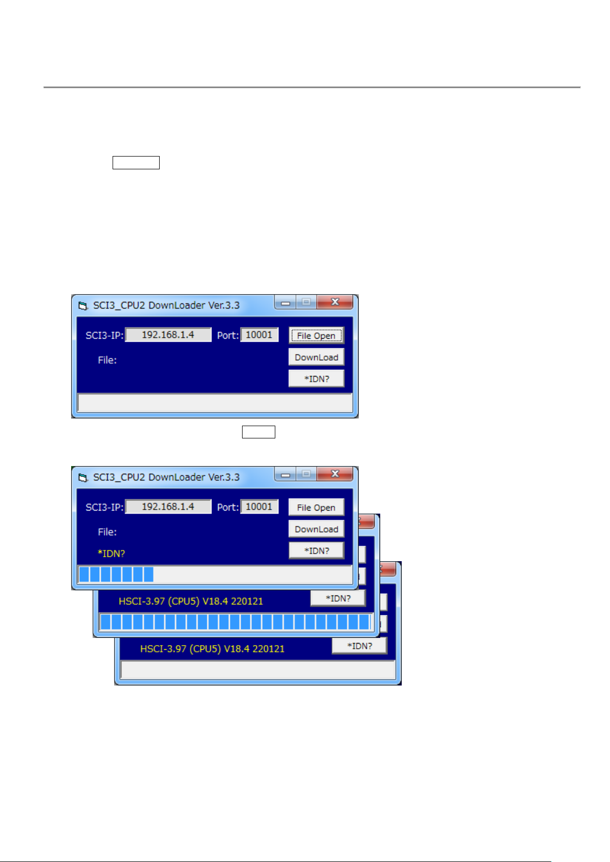
4) After startup, the following window will be displayed.
Note) For this model, change the IP address to the following.
(192.168.1.4 ⇒192.168.1.14)
5) To check the current program Ver. Click *IDN? .
Ver. Information will be displayed.
Display example "HSCI-3.97 (CPU5) V18.4 220121"
================ ===== ======
| | |
-----------|------|--> Product name (CPU board name)
-------|--> ROM Ver.
---> ROM Ver. Updated date (yymmdd)

15
6) Click FileOpen to display the file selection window.
Select the program file (SCI3_*.MOT) to be downloaded. (Select the latest Ver.)
The program file is in the ¥CPU2-SH4 folder.
The selected file name will be displayed in the next window.
7) When a file is selected, the file name is displayed in the following window.
To reselect, click FileOpen again.
16
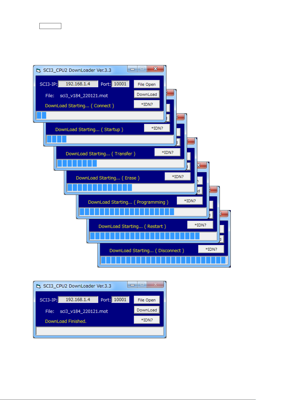
8) Click DownLoad to start the download.
9) Below is the transition of the screen during downloading.
While downloading, the CAN, LIN and ERR indicators blink simultaneously.
The download ends in about 30 seconds.
10) Below is the screen at the end of download.
11) Quit the PC side program and turn off the power of this unit.
The update of the program is now complete.

17
6. Revision History
Revision
Date
Description
Feb.28,2011
The 1st edition was newly created.
1st
May 10,2011
Changed the shipping settings of the Ethernet IP address.
(Consideration the link with SCI monitor 3.)
Ethernet side
192.168.1.4 ⇒192.168.1.14
Ethernet-M side
192.168.1.204(No change)
2nd
Jun.30,2011
Added SH4 high-speed download function on CPU2 side.
In addition to the conventional SERIAL, a download function via Ethernet has been added.
5.5 How to use the downloader (for CPU2-SH4: via Ethernet)
* This function is available in [SCI3_V94.mot] and later versions.
3rd
Jan.13,2012
Added the inter-host communication monitor function via Ethernet on the CPU2 side.
In addition to the conventional SERIAL, a host-to-host communication monitoring
function via Ethernet has been added.
2.7 Inter-host communication monitor function
2. Procedure when using the monitor function via Ethernet
4th
May 09,2012
The "LAN-GPIB" communication mode on the CPU2 side was disabled.
CPU2 side Ethernet3-Corrected the related description by changing the number of ports
(4⇒2 ports).
(192.168.1.204/20001~20004⇒192.168.1.204/20001,20002)
5.4 How to use the downloader (for CPU2-SH4: via Ethernet)
Changed the description of "LAN cable" to be used.
⇒The LAN cable can be used with either "straight" or "cross".
5th
May 16,2019
The contents of the description have been revised.
Table of contents
Popular Conference System manuals by other brands

NEC
NEC Univerge UM8000 user guide

Qufield Co., Ltd.
Qufield Co., Ltd. LM-D100US instruction manual

Bosch
Bosch DICENTIS Configuration manual

Grandstream Networks
Grandstream Networks GVC3200 Phonebook guide

LY International Electronics
LY International Electronics H-8000 instruction manual

Cisco
Cisco TelePresence MX700 reference guide

AT&T
AT&T MERLIN LEGEND Release 2.0 Analog Multiline... Data user's guide

Panasonic
Panasonic KX-NS300 Cabling configuration

Rath
Rath Command Center Installation & operation manual

Hubbell
Hubbell GAI-TRONICS 234WM Assembly

EZTalks
EZTalks Meet Pro Quick user guide

Lincoln Electric
Lincoln Electric Power Wave K4352 Operator's manual


