Power Wave Communication Kit Installation Instructions
Recommended Tools:
•5/16” nut driver or other suitable tools
CAUTION : PC BOARD CAN BE DAMAGED BY STATIC ELECTRICITY
Before making any connections to a PC board, remove your body’s static charge by touching unpainted
grounded frame of equipment.
INSTALLATION:
1. Turn off input power to the Power Wave at the disconnect switch or fuse box before working
on the Power Wave.
2. Remove the weld cables from the output studs, and disconnect all control cables including the
Ethernet connection from the Power Wave.
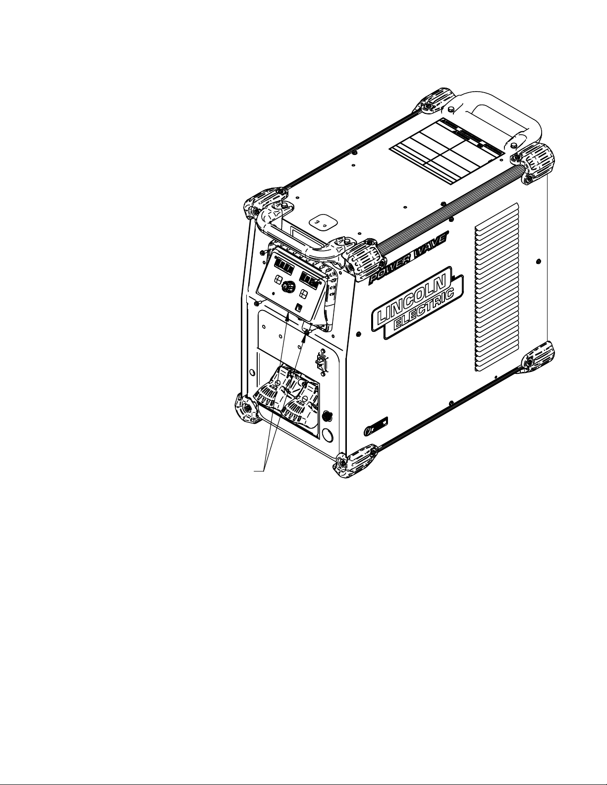
3. Remove the UI cover plate by removing the four screws fastening the cover plate to the power
source using a 5/16” nut driver or other suitable tool (Figure 1). Retain the mounting hardware
removed for installing the Power Wave Communication Kit.
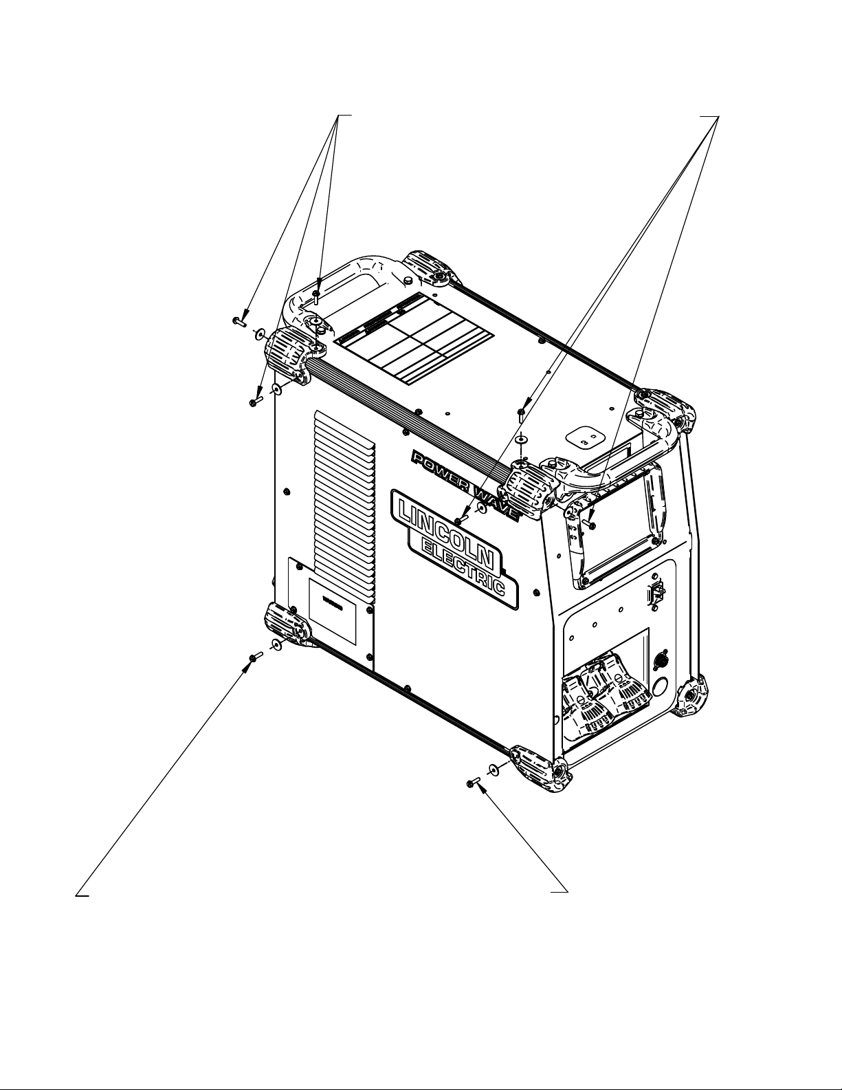
4. Remove the two top left Corner Caps by removing the screws and washers mounting them,
using a 5/16” nut driver or other suitable tool (Figure 2). Retain all mounting hardware for
reinstalling the Corner Caps.
5. Remove the bottom left Corner Cap fasteners, two places, using a 5/16” nut driver or other
suitable tool (Figure 2). Retain all mounting hardware for reinstalling the Corner Caps.
6. Remove the left case side by removing the four screws mounting them, using a 5/16” nut driver
or other suitable tool (Figure 3). Retain all mounting hardware for case side.
7. Obtain Item 1 Power Wave Communication Module provided with the kit. Route the 4-pin
connector P30 of the Power Wave R450 harness thru the case front, and to J30 of Item 1Power
Wave Communication Module (Figure 4).
8. Install the Power Wave Communication Module to the Case Front using the hardware removed
from cover plate in Step 3, using a 5/16” nut driver or other suitable tool (Figure 5).
9. Install the left case side using the hardware removed from mounting the left case side in Step 6
using a 5/16” nut driver or other suitable tool (Figure 6).
10. Install the bottom left Corner Caps using the hardware removed from mounting the corner caps
in Step 5, using a 5/16” nut driver or other suitable tool (Figure 7).
11. Install the top left Corner Caps by using the hardware removed from mounting the Corner Caps
in step 5, using a 5/16” nut driver or other suitable tool (Figure 8).
12. Replace the weld cables from the output studs, and reconnect all control cables including the
Ethernet connection from the Power Wave.
13. The WiFi and Bluetooth are disabled as shipped from the factory.
14. After installing the K4352 Power Wave Communication Kit, the Power Wave firmware
may need to be updated. Visit www.powerwavesoftware.com for firmware updates and
the Power Wave Utilities. Included with Power Wave Utilities are the Power Wave
Manager PC tool for setting up the wireless or Bluetooth connection, and the Help Me
Connect guide for setup instructions.
2
K4352 POWER WAVE COMMUNICATION KIT
POWER WAVE R450 (ALL CODES)