Hubbell GAI-TRONICS 234WM User manual

Pub. 42004-308C
GAI-Tronics Corporation P.O. Box 1060, Reading, PA 19607-1060 USA
610-777-1374 800-492-1212 Fax: 610-796-5954
VISIT WWW.GAI-TRONICS.COM FOR PRODUCT LITERATURE AND MANUALS
GAI-TRONICS® CORPORATION
A HUBBELL COMPANY
Model 234WM
Wall-Mount Stanchion Assembly
Confidentiality Notice
This manual is provided solely as an operational, installation, and maintenance guide and contains
sensitive business and technical information that is confidential and proprietary to GAI-Tronics. GAI-
Tronics retains all intellectual property and other rights in or to the information contained herein, and
such information may only be used in connection with the operation of your GAI-Tronics product or
system. This manual may not be disclosed in any form, in whole or in part, directly or indirectly, to any
third party.
General Information
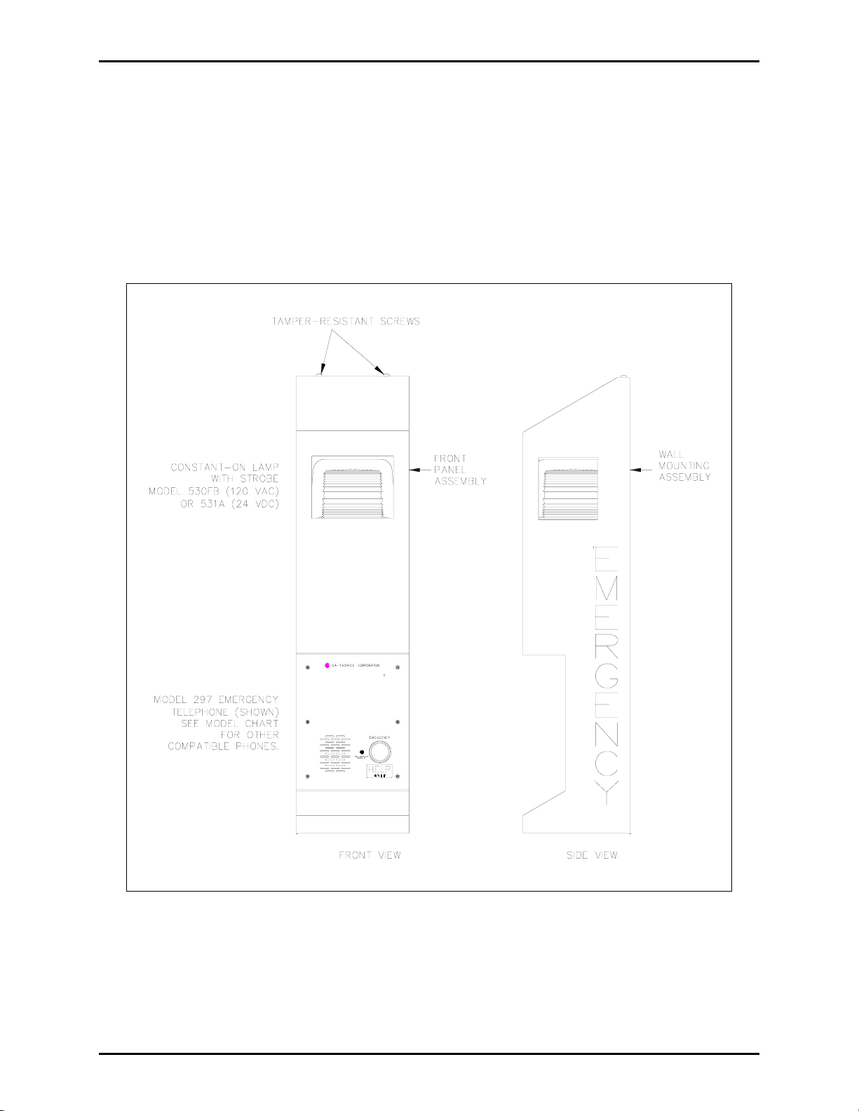
The Model 234WM Wall-Mount Stanchion Assembly is designed to house a Model 298 Series or 297
Series Emergency Telephone or Model 276 Series or 277 Series Flush Panel Handset Telephone, and a
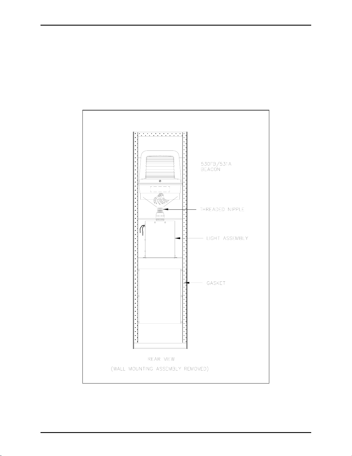
Model 530FB or 531A Beacon (each sold separately). The stanchion is a simple, attractive, yet highly
visible unit measuring 40.5 inches (1.03 meters) tall.
GAI-Tronics emergency telephones are designed for isolated high-risk areas requiring emergency
communications equipment. Emergency telephone users simply press the clearly labeled emergency push
button for immediate connection to a user-programmed central security telephone number. The following
is a list of GAI-Tronics telephone models that are compatible for use in the Model 234 Wall-Mount
Stanchion and the associated instruction publication number:
Pub. No. Emergency Phone Model
Pub. 42004-352 Model 297-001 Flush-Mount Emergency Phone
Pub. 42004-351 Model 297-003 S.M.A.R.T. Flush-Mount Emergency Phone
Pub. 42004-352 Model 298-001 Flush-Mount Emergency Phone with Keypad
Pub. 42004-351 Model 298-003 S.M.A.R.T. Flush-Mount Emergency Phone with Keypad
The beacon increases the visibility of the emergency telephone locations by providing a constant-on lamp
and a flashing strobe light that is automatically energized when the emergency button is pressed. A light
shines on the faceplate of the telephone mounted in the stanchion, illuminating it for nighttime use. Refer
to Pub. 42004-284 for installation information for the Model 530FB Strobe with Dual Constant-On
Lamps.

Pub. 42004-308C
Model 234WM Wall-Mount Stanchion Assembly Page: 2 of 12
d:\standard ioms - current release\42004 instr. manuals\42004-308c.doc
09/05
The Model 234WM Wall-Mount Stanchion Assembly, which consists of the Model 84505 Wall-Mount
Stanchion, the Model 84503 Panel Light Assembly, the 530 Series Strobe, and the emergency phone, is
shipped in four separate cartons.
NOTE:Emergency phone and strobe are sold separately.
Installation
The following sections provide information on the installation of the complete wall-mount stanchion.
Figure 1. Model 234WM Wall-Mount Stanchion Assembly

Pub. 42004-308C
Model 234WM Wall-Mount Stanchion Assembly Page: 3 of 12
d:\standard ioms - current release\42004 instr. manuals\42004-308c.doc
09/05
Model 84505 Wall-Mount Stanchion Installation
1. Remove and save the two tamper-resistant screws at the top of the stanchion. See Figure 1.
NOTE:GAI-Tronics Model 233 Tamper-Resistant Screwdriver (sold separately) is required to
remove tamper-resistant screws.
2. Remove the wall-mounting assembly from the front panel assembly. Refer to Figure 1. Detach the
chain from the wall-mounting assembly. See Figure 2.
3. Enlarge the conduit entry pilot hole(s) to be used for the stanchion power cables. See Figure 3.
4. Fasten the wall-mounting assembly to a wall or flat surface that can support at least 50 pounds, using
3/8-inch bolts. Refer to Figure 2 for mounting hole dimensions and ADA height requirements.
Figure 2. Wall Mounting Instructions

Pub. 42004-308C
Model 234WM Wall-Mount Stanchion Assembly Page: 4 of 12
d:\standard ioms - current release\42004 instr. manuals\42004-308c.doc
09/05
Grounding Requirements
This unit must be grounded in accordance with the National Electrical Code (NEC) in the United States or
the Canadian Electrical Codes (CEC) in Canada. A #10 grounding stud has been provided at the base of
the stanchion for grounding. Connect the #10 grounding stud to a grounding electrode. A grounding
electrode rod is typically 8 feet (2.44 m) long per NEC 250, or 9.84 feet (3 m) long per CEC Rule 10.
Figure 3. Conduit/Surge Protection Locations

Pub. 42004-308C
Model 234WM Wall-Mount Stanchion Assembly Page: 5 of 12
d:\standard ioms - current release\42004 instr. manuals\42004-308c.doc
09/05
Tempered Glass Installation for Model 84505
1. Remove the keps nuts, spacer brackets, and holding brackets. These parts will be used for holding the
glass in place.
2. Carefully unpack the glass from the box, located in the phone mounting area of the Model 234WM
Wall-Mount Stanchion.
3. Center the front glass left to right and top to bottom around the opening in the front panel assembly
and fasten in place using the spacer brackets, holding brackets, and keps nuts removed previously.
Refer to Figure 4 for assembly details.
NOTE:Do not exceed 24 inch-pounds of torque on the keps nuts.
4. Repeat the above steps for both side glass pieces.
Figure 4. Glass Installation Instructions

Pub. 42004-308C
Model 234WM Wall-Mount Stanchion Assembly Page: 6 of 12
d:\standard ioms - current release\42004 instr. manuals\42004-308c.doc
09/05
Model 84503 Stanchion Panel Light Installation
1. Remove the two screws securing the bezel and lens to the stanchion panel light assembly.
2. Align the stanchion panel light assembly inside the stanchion as shown in Figure 5.
3. Extend the black, white, and green wires to the bottom of the stanchion.
4. Secure the panel light assembly with the two mounting screws provided. Apply a small amount of
clear RTV silicone sealant or equivalent to each screw thread to reduce the possibility of rust forming
in the screw threads.
5. Insert the 7-watt compact fluorescent bulb provided with the assembly.
6. Secure the bezel and the lens to the stanchion. See Figure 5.
Figure 5. Stanchion Panel Light Assembly

Pub. 42004-308C
Model 234WM Wall-Mount Stanchion Assembly Page: 7 of 12
d:\standard ioms - current release\42004 instr. manuals\42004-308c.doc
09/05
Model 530FB or Model 531A Beacon Installation
1. Insert the beacon’s seven 15-foot wires through the stanchion’s threaded nipple, and allow the wires
to extend to the bottom of the stanchion. See Figure 6.
2. Screw the beacon onto the threaded nipple.
3. Separate the orange and violet wires necessary for the telephone connection and extend those wires
through the stanchion cutout for the telephone.
Figure 6. Beacon Assembly

Pub. 42004-308C
Model 234WM Wall-Mount Stanchion Assembly Page: 8 of 12
d:\standard ioms - current release\42004 instr. manuals\42004-308c.doc
09/05
Emergency Telephone Installation
1. Separate the back box from the front panel of the telephone. Inside the back box is a parts envelope
is containing eight 6-32 self-tapping flat head screws, six tamperproof screws, six washers, and a hole
plug.
2. Place the back box into the phone opening from the front of the stanchion. Mount the box using four
of the 6-32 self-tapping flat head screws. Refer to Figure 7 below. The telephone back box has two
openings, one in the top and one in the bottom. Plug the top opening with a hole plug. The bottom of
the back box is the recommended entry location for the telephone line and strobe control wires.
Figure 7. Telephone and Back Box Installation
3. Install a telephone line surge suppressor (sold separately) on the protection bracket on the bottom of
the stanchion wall mounting assembly. See Figure 3.
4. Install a ground wire between the telephone line surge suppressor (sold separately) and the grounding
lug on the bottom of the stanchion. See Figure 8.
5. Connect the telephone line to the surge protection as shown in Figure 8.

Pub. 42004-308C
Model 234WM Wall-Mount Stanchion Assembly Page: 9 of 12
d:\standard ioms - current release\42004 instr. manuals\42004-308c.doc
09/05
6. Connect the telephone cable from the surge protection, and feed the cable through the bottom access
hole of the telephone back box and allow it to hang free.
7. Bring the orange and violet strobe unit wires through the bottom access hole of the back box, and
allow them to hang free.
8. The telephone front panel is shipped from the factory with a cable and modular plug attached to TB1.
If the telephone line is to be hard-wired to the phone, this cable can be removed and discarded. Skip
to Step 9. If desired, an optional modular telephone jack can be mounted to the inside of the back box
allowing the use of the cable and modular plug that is attached to TB1.
9. Attach the telephone cable from the surge protector to TB1 on the telephone PCBA as shown in
Figure 8.
10. Attach the strobe’s violet and orange control wires to TB2 on the telephone PCBA as shown in
Figure 8.
11. Install the phone’s front panel using the six tamper-resistant screws and six washers provided.
NOTE:Excessive tightening will cause the panel to warp. Do not over-tighten.
Figure 8. Interconnection diagram with ac beacon

Pub. 42004-308C
Model 234WM Wall-Mount Stanchion Assembly Page: 10 of 12
d:\standard ioms - current release\42004 instr. manuals\42004-308c.doc
09/05
Wiring Power Connection
All wiring connections should be complete at this point, with the exception of the stanchion panel light
and beacon wire connections to the incoming power lines. All connections must be made in accordance
with the National Electrical Code (NEC) in the United States or the Canadian Electrical Codes (CEC) in
Canada.
Install the power lines as follows:
1. Install the recommended ac power line surge suppressor on the protection bracket.
2. Install a ground wire between the telephone line surge protection and the grounding lug.
3. Connect the incoming ac power line to the surge protection as shown in Figure 8.
4. Connect the red, white, and green wires of the Model 530FB AC Beacon to the surge protection as
shown in Figure 8. When using the Model 531A DC Beacon, connect the red and white wires to the
dc power source as shown in Figure 9.
5. Connect the black, white, and green wires of the telephone light to the surge protection.
Figure 9. Interconnection diagram with dc beacon

Pub. 42004-308C
Model 234WM Wall-Mount Stanchion Assembly Page: 11 of 12
d:\standard ioms - current release\42004 instr. manuals\42004-308c.doc
09/05
Repairing Surface Damage to Powder-Coated Stanchions
Scratch Repair
1. Carefully sand the damaged area to clean and score the base metal, taking care to minimize any
additional damage to the surrounding powder coating.
2. Wipe the sanded area with a cleaning solvent, such as DuPont “PrepSol” or equivalent. Allow the
area to dry. This type of product is normally available at auto parts stores. Denatured alcohol may
also be used.
3. Prepare the bare metal surface for painting by treating it with a phosphoric acid solution intended for
this purpose. The phosphoric acid solution is also normally available at auto parts stores. Allow the
area to dry.
4. Using a cotton-tipped swab or small brush, paint the prepared surface with an automotive enamel or
oil base polyurethane enamel such as Red Devil, Rustoleum, or equivalent. Do NOT use Krylon-type
paints. Carefully blend the repair enamel into the powder coat at the edges.
NOTE:Exact color matches may not be attainable.
Decal Repair
1. Using a very sharp instrument such as an X-Acto-type knife, loosen then lift a corner edge of the
damaged decal.
2. Carefully peel back and remove the loosened decal.
3. Wipe the area clean with denatured alcohol. Allow the area to dry.
4. Prior to attaching a new decal, dampen the target area with a fine mist of water (fine spray from a
plant misting bottle is ideal).
5. Peel the backing from the replacement decal, leaving the decal attached to the front cover material,
and carefully align it with the target area.
6. With the cover material still attached, press the replacement decal in place, then squeegee any water
from under the new decal starting at the center and working toward the edges.
7. Peel off the cover material, being careful not to tear or lift the decal. If the decal lifts as the cover
material is being removed, push down on the uncovered decal, and squeegee as necessary to remove
any large bubbles; small bubbles will disappear as the decal dries.

Pub. 42004-308C
Model 234WM Wall-Mount Stanchion Assembly Page: 12 of 12
d:\standard ioms - current release\42004 instr. manuals\42004-308c.doc
09/05
Specifications
Dimensions .........................................................10 W ×9.5 D ×40.5 H inches (0.25 ×0.24 ×1.03 meters)
Wall thickness...................................................................................................................1/8-inch aluminum
Finish ...................................................................................................................................... Powder-coated
Power ratings:
AC Beacon:................................................Model 530FB - 0.69 amps @ 120 V ac
DC Beacon:......................................................Model 531A - 2.7 amps @ 24 V dc
Panel Light Assembly:..................................Model 84503 - 0.2 amps @ 120 V ac
Weight......................................................................................................................... Approximately 40 lbs.
Approvals
UL/cUL listed telephone stanchion................................Canadian Electrical Code, Part I (CE Code, Part I),
and the ANSI/NFPA 70 National Electrical Code (NEC).

(Rev. 1/97)
Warranty
Equipment.GAI-Tronics warrants for a period of one (1) year from the date of shipment, that any
GAI-Tronics equipment supplied hereunder shall be free of defects in material and workmanship, shall
comply with the then-current product specifications and product literature, and if applicable, shall be fit
for the purpose specified in the agreed upon quotation or proposal document. If (a) Seller’s goods prove
to be defective in workmanship and/or material under normal and proper usage, or unfit for the purpose
specified and agreed upon, and (b) Buyer’s claim is made within the warranty period set forth above,
Buyer may return such goods to GAI-Tronics nearest depot repair facility, freight prepaid, at which time
they will be repaired or replaced, at Seller’s option, without charge to Buyer. Repair or replacement shall
be Buyer’s sole and exclusive remedy, and the warranty period on any repaired or replacement equipment
shall be one (1) year from the date the original equipment was shipped. In no event shall GAI-Tronics
warranty obligations with respect to equipment exceed 100% of the total cost of the equipment supplied
hereunder. Buyer may also be entitled to the manufacturer’s warranty on any third-party goods supplied
by GAI-Tronics hereunder. The applicability of any such third-party warranty will be determined by
GAI-Tronics.
Services. Any services GAI-Tronics provides hereunder, whether directly or through subcontractors,
shall be performed in accordance with the standard of care with which such services are normally
provided in the industry. If the services fail to meet the applicable industry standard, GAI-Tronics will,
for a period of one (1) year from the date of completion, re-perform such services at no cost to Buyer. Re-
performance of services shall be Buyer’s sole and exclusive remedy, and in no event shall GAI-Tronics
warranty obligations with respect to services exceed 100% of the total cost of services provided
hereunder.
Warranty Periods. Every claim by Buyer alleging a defect in the goods and/or services provided
hereunder shall be deemed waived unless such claim is made in writing within the applicable warranty
periods as set forth above. Provided, however, that if the defect complained of is latent and not
discoverable within the above warranty periods, every claim arising on account of such latent defect shall
be deemed waived unless it is made in writing within a reasonable time after such latent defect is or
should have been discovered by Buyer.
Limitations / Exclusions. The warranties herein shall not apply to, and GAI-Tronics shall not be
responsible for, any damage to the goods or failure of the services supplied hereunder, to the extent
caused by Buyer’s neglect, failure to follow operational and maintenance procedures provided with the
equipment, or the use of technicians not specifically authorized by GAI-Tronics to maintain or service the
equipment. THE WARRANTIES AND REMEDIES CONTAINED HEREIN ARE IN LIEU OF AND
EXCLUDE ALL OTHER WARRANTIES AND REMEDIES, WHETHER EXPRESS OR IMPLIED
BY OPERATION OF LAW OR OTHERWISE, INCLUDING ANY WARRANTIES OF
MERCHANTABILITY OR FITNESS FOR A PARTICULAR PURPOSE.
Return Policy
If the equipment requires service, contact your Regional Service Center for a return authorization number
(RA#). Equipment should be shipped prepaid to GAI-Tronics with a return authorization number and a
purchase order number. If the equipment is under warranty, repairs or a replacement will be made in
accordance with the warranty policy set forth above. Please include a written explanation of all defects to
assist our technicians in their troubleshooting efforts.
Call 800-492-1212 (inside the USA) or 610-777-1374 (outside the USA) for help identifying the
Regional Service Center closest to you.
Table of contents
Other Hubbell Conference System manuals