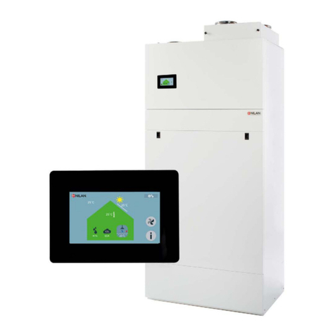
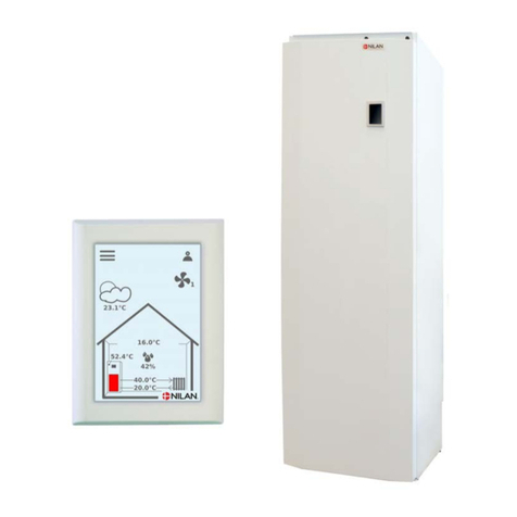
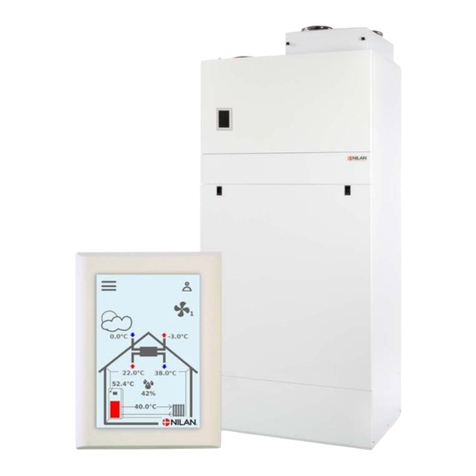
nilan Comfort 600 User manual

USER MANUAL
CTS602 HMI BY NILAN
Comfort 600 (English)
Version 3.00 - 01.10.2019

TABLE OF CONTENTS
Safety
Power supply................................................................................................................................................................................................................................................................... 3
Disposal............................................................................................................................................................................................................................................................................................. 3
Ventilation unit............................................................................................................................................................................................................................................................. 3
General information
Introduction...................................................................................................................................................................................................................................................................... 4
Type plate........................................................................................................................................................................................................................................................................... 4
Quick guide
Functions of control panel............................................................................................................................................................................................................................................ 5
Main screen elements........................................................................................................................................................................................................................................... 5
Settings options on the main screen.....................................................................................................................................................................................................6
Warnings and alarms.............................................................................................................................................................................................................................................. 7
Settings menu overview..................................................................................................................................................................................................................................... 8
Service and maintenance
Maintenance................................................................................................................................................................................................................................................................................ 9
Bypass function............................................................................................................................................................................................................................................................9
Maintenance ................................................................................................................................................................................................................................................................... 9
Water trap...........................................................................................................................................................................................................................................................................9
The exchanger................................................................................................................................................................................................................................................................9
Illustration of filter change.......................................................................................................................................................................................................................... 10
Service............................................................................................................................................................................................................................................................................................ 11
Annual service .......................................................................................................................................................................................................................................................... 11
Internal cleaning ..................................................................................................................................................................................................................................................... 11
Check the air intake and outlet .............................................................................................................................................................................................................. 11
Check ventilation ducts .................................................................................................................................................................................................................................. 11
User settings
Ventilation settings..........................................................................................................................................................................................................................................................12
Stop the unit................................................................................................................................................................................................................................................................. 12
Operation function................................................................................................................................................................................................................................................ 12
Alarm.................................................................................................................................................................................................................................................................................... 13
Show data........................................................................................................................................................................................................................................................................14
Date/Time.......................................................................................................................................................................................................................................................................15
Week program............................................................................................................................................................................................................................................................ 16
After-heating.............................................................................................................................................................................................................................................................. 17
Air humidity...................................................................................................................................................................................................................................................................18
CO2 .........................................................................................................................................................................................................................................................................................19
Air exchange.................................................................................................................................................................................................................................................................20
Air filter..............................................................................................................................................................................................................................................................................20
Temp. control.............................................................................................................................................................................................................................................................. 21
Language..........................................................................................................................................................................................................................................................................22
Alarm list
Comfort unit............................................................................................................................................................................................................................................................................. 23
Alarm list ......................................................................................................................................................................................................................................................................... 23
Product data
Declaration of compliance............................................................................................................................................................................................................................ 25
Ecodesign data Comfort 600......................................................................................................................................................................................................................26
2
Safety
Power supply
CAUTION
Always disconnect the power supply to the unit if an error occurs that cannot be rectified via
the control panel.
CAUTION
If an error occurs on electrically conductive parts of the unit, always contact an authorised
electrician to rectify the error.
CAUTION
Always disconnect the power supply to the unit before opening the unit doors, for instance for
installation, inspection, cleaning and filter change.
Disposal
Ventilation unit
Nilan’s units consist mainly of recyclable materials. They must, therefore, not be
mixed with household waste, but must be delivered to your local recycling center
for disposal.
Comfort 600 (English) BY NILAN
3

General information
Introduction
ATTENTION
The unit must be started up immediately after installation and connection to the duct system.
When a ventilation unit is not in operation, humidity from the rooms may penetrate into the
ducts and create condensation. Condensate water may leak out of the valves and damage
furniture and floors. Condensation may also form inside the unit, which can damage its
electronics and fans.
The unit is delivered fully tested and ready for operation.
Type plate
On the right side of the unit you will find the Nilan type plate.
Note: Contact Nilan a/s with questions about the product, it is important to have the unit name and
serial No. (SN) ready. On the basis of this information, please contact service department find all
informations about the relevant aggregate and thus provide information and answer questions about
what the aggregate consists of/contains, as well as the software used.
4

Quick guide
Functions of control panel
Main screen elements
The main screen of the HMI panel contains the settings options and the information that an operator
mostly uses.
1. Shows the current room temperature in the
house, measured via the extract air.
2. Shows the current air humidity.
3. Shows the CO2 level in the house,2 -provided
the unit is equipped with a CO22 sensor.
4. Shows the current fan speed level.
5. Shows user selection and week program if
these are activated. If the unit is off, the stop
symbol will be displayed and it will say “off”
next to fan speed level. At warnings or alarms
the alarm icon will be displayed.
6. Access to the settings menu, where there are
several settings options.
User selection icon
Stop icon
Week program icon
Alarm icon
Comfort 600 (English) BY NILAN
5

Settings options on the main screen
The settings options which the user needs in daily life can all be controlled from the main screen of the
panel.
If you select the option of current room temperature, the
desired room temperature will be displayed.
The desired room temperature can be adjusted by pressing
the up-or-down arrows followed by the cancel icon (bottom
left) or the accept icon (bottom right).
If you select the option of current fan speed level, the
desired fan speed level will be displayed.
The desired fan speed level can be adjusted by pressing the
up-or-down arrows followed by the cancel icon (bottom left)
or the accept icon (bottom right).
6

Warnings and alarms
Should an error occur in the operation of the unit, a warning or an alarm will be displayed. A warning will
be displayed in the top righthand corner in the menu bar.
If you select the symbol, a description of
the warning or the alarm will be displayed.
The warning or the alarm can be reset by
selecting "Clear Alarm".
A warning indicates that something requires attention, for instance that filters need
changing.
The unit operates normally.
An alarm indicates a serious fault with the unit that is likely to require an expert.
The unit has stopped.
Comfort 600 (English) BY NILAN
7

Settings menu overview
The settings menu is constructed to make it easy to navigate through.
8

Service and maintenance
Maintenance
Bypass function
When the current room temperature is above the desired temperature, there is no longer need for heat
recovery. In this situation, open bypasset and leader of outside air past the heat exchanger sober. This
results in lower internal pressure in the unit and you thereby save energy on fan operation.
Maintenance
Nilan’s ventilation units last for many years, but to get the best out of them whilst avoiding
unnecessary electricity consumption, correct maintenance is important.
The following parts require regular maintenance:
• Water trap
• Filters
Water trap
The water trap can dry out and prevent water from draining from the condensate tray, because air will
then blow into the unit. Condensate water will accumulate in the condensate tray. This will eventually
overflow and potentially cause water damage to the surface supporting the unit.
The water trap should therefore be checked regularly and filled with water, especially in the summer
when the risk of the water trap drying out is highest.
The exchanger
The exchanger should be checked for dust and dirt every two years to ensure that air can pass through
unhindered. A blocked exchanger will increase power consumption.
Comfort 600 (English) BY NILAN
9

Illustration of filter change
1. Before opening the door, switch the unit off on the
control panel under OPERATION. This is situated in the
main menu SETTINGS
2. The screws loosened in the upper cover and pull the
cover lifted out
3. Remove the two filters from the unit 4. It is advisable that you vacuum the filter chambers for
potential dirt and dust
5. Remove the filter sheet from the filter frame 6. Keeping the smooth side facing downwards, place the
new filter sheet in the filter frame
7. Press the filter sheet firmly in place and carefully push
it to the sides of the filter frame. The filter is placed back
in the unit with filter mat upward
In the ALARM menu on the control panel, press the alarm
symbol at the top right and reset the alarm here.
10

Service
Annual service
It is important to perform an annual service on the unit to ensure it will continue to perform optimally
with low energy consumption and long service life.
You are recommended to take out a service agreement with the installer, as certain elements of the
service require an authorised technician.
Internal cleaning
For hygienic reasons, it is important that the unit undergoes annual internal cleaning. This will prevent
the formation of fungus and bacteria which impair the internal air quality.
• Wipe down the internal plate parts and pipes with a damp cloth and a mild soap solution.
• Check and clean the evaporator coil.
• Check and clean the counterflow heat exchanger. If necessary, it may be removed and rinsed with a
shower head.
• Clean the condensate trays with a damp cloth and a mild soap solution.
• Check the condensate outlet to make sure the water can exit freely.
Check the air intake and outlet
It is important for operation of the unit that air can freely move through the air intake and outlet.
If roof stacks have been fitted to the air intake and outlet, check that they are not blocked with birds'
nests, leaves or other dirt which can hamper air passage.
If, instead of roof stacks, grilles have been mounted in facades or eaves, check that they are not
clogged with leaves or dirt. Grilles are particularly likely to become clogged.
Check ventilation ducts
It is important for operation of the unit that there is free air passage through the ventilation ducts.
After some years of operation, dirt will attach itself to ventilation ducts or tubes, and accumulations
may lead to higher pressure drop in the ducts, leading to higher power consumption. It is therefore
important to clean out the ducts when too much dirt has collected.
After attending to the inlet and outlet valves, it will be advisable to have them adjusted again, to
ensure optimum operation of the ventilation system.
However, it will not be necessary to clean ducts more than every few years.
Comfort 600 (English) BY NILAN
11

User settings
Ventilation settings
Stop the unit
If it is necessary to open the doors while servicing the unit, for instance when changing filters, the unit
must be turned off.
The functions of the unit are activated in Settings under Operation.
If the unit is off, an icon appears on the main screen.
Operation
↳Operation Settings:
Description:
Off / On
The unit must be turned off before the doors are
opened during a service
Operation function
It is possible to provide the unit with an input which determines whether it will operate in Auto, Heating
or Cooling.
ATTENTION
Features "Heating" and "Bypass" overrules weekly plan. The system will automatically change
to Auto on the next change in the week program, if such is programmed.
Operation function
↳Auto Settings:
Standard setting:
Description:
Auto/Bypass/Heating
Auto
Auto: The unit operates in accordance with the set
values.
Bypass: Unit running after the preset values, but do
not use heat recovery
Heating: Unit running after the preset values, and
bypass damper can not open.
12

Alarm
You can read warnings and alarms in the "Alarm" menu. It is likewise possible to reset warnings and
alarms in this menu.
When a warning or an alarm has been triggered, an icon appears on the main screen
Alarm
↳Alarm number and name Description: When selecting this, a list will appear showing the
alarm ID number, information about the type of alarm,
and whether it is critical or not. (See the alarm list for
more information)
You can approve the alarm by selecting "Clear Alarm”
ATTENTION
When an alarm is active, it cannot be reset in the panel. When the alarm has been resolved, it will
figure as inactive and it can be reset by selecting "Clear Alarm”.
Comfort 600 (English) BY NILAN
13

Show data
It is possible to read off relevant data for Comfort units.
Show data
↳Operating state Description: Shows the operating setting in which the unit is
running.
↳Bypass Description: Shows whether the bypass damper is open or closed.
↳T2 Supply air Description: Shows the supply air temperature. If an after-heating
element has been installed, T7 will be shown instead.
↳T3 Extract air / Room Description: Shows the room temperature as an average of the
entire house.
↳T4 Discharge Description: Shows the discharge air temperature.
↳T7 Supply air Description: Shows the supply air temperature provided an after-
heating element has been installed. Otherwise T2 will
be shown.
↳T8 Outdoor air Description: Shows the outdoor temperature before reaching the
pre-heating element.
↳T9 Water heating element Description: Shows the temperature in the water after-heating
element.
↳T10 External Description: Displays the external room temperature
↳Air humidity Description: Shows the current air humidity in the house.
↳CO2 Description: Shows the current CO22 level in the house (only if
installed).
↳Supply air fan Description: Shows the level at which the supply air fan is
operating.
↳Extract air fan Description: Shows the level at which the extract air fan is
operating.
↳Unit information Description: Select "Unit information" for more information.
↳Unit type Description: Shows the name of the product the software has been
set to work with.
↳Software version Description: Shows the installed software version.
↳Panel software Description: Shows installed software version on the panel.
14

Date/Time
It is important to set date and time correctly. It makes it easier to localise errors indicated in an error
report. When logging data, it is important to be able to follow the history. The time is shown under
“Date / Time” in the display.
Date / Time
↳Year Description: Select "Year" in the panel and then select the correct
year.
↳Month Description: Select "Month" in the panel and then select the correct
month.
↳Day Description: Select "Day" in the panel and then select the correct
day.
↳Hour Description: Select "Hour" in the panel and then select the correct
hour.
↳Minute Description: Select "Minute" in the panel and then select the correct
amount of minutes.
Comfort 600 (English) BY NILAN
15

Week program
You can program the unit to run in accordance with specific settings at fixed times during the week via
a week program.
On the main screen an icon will be displayed when the week program is active
Week program
↳Select program Description: You can select from the Programs 1, 2, 3 or off.
↳Edit program Description: The selected week program is now active and can be
edited.
↳Monday Description: You can select either Monday, Tuesday, Wednesday,
Thursday, Friday, Saturday or Sunday.
↳Function 1 Description: Under each function, you can set time, temperature
and fan speed level.
↳Start time Settings:
Standard setting:
Description:
Hours and minutes
6:00
Set the time for the program to start.
The program will run until the next change in the week
program.
↳Ventilation Settings:
Standard setting:
Description:
Level 1 / Level 2 / Level 3 / Level 4 / Off
Level 3
Select the desired fan speed level here.
↳Temperatures Settings:
Standard setting:
Description:
5 - 40 °C
22 °C
Set the desired room temperature here.
↳Function 2 Under each function, you can set time, temperature
and fan speed level.
↳Start time Settings:
Standard setting:
Description:
Hours and minutes
8:00
Set the time for the program to start.
The program will run until the next change in the week
program.
↳Ventilation Settings:
Standard setting:
Description:
Level 1 / Level 2 / Level 3 / Level 4 / Off
Level 1
Select the desired fan speed level here.
↳Temperatures Settings:
Standard setting:
Description:
5 - 40 °C
22 °C
Set the desired room temperature here.
↳Function 3 Description: Under each function, you can set time, temperature
and fan speed level.
↳Start time Settings:
Standard setting:
Description:
Hours and minutes
15:00
Set the time for the program to start.
The program will run until the next change in the week
program.
↳Ventilation Settings:
Standard setting:
Description:
Level 1 / Level 2 / Level 3 / Level 4 / Off
Level 3
Select the desired fan speed level here.
↳Temperatures Settings:
Standard setting:
Description:
5 - 40 °C
22 °C
Set the desired room temperature here.
↳Function 4 Description: Under each function, you can set time, temperature
and fan speed level.
16

↳Start time Settings:
Standard setting:
Description:
Hours and minutes
22:00
Set the time for the program to start.
The program will run until the next change in the week
program.
↳Ventilation Settings:
Standard setting:
Description:
Level 1 / Level 2 / Level 3 / Level 4 / Off
Level 1
Select the desired fan speed level here.
↳Temperatures Settings:
Standard setting:
Description:
5 - 40 °C
22 °C
Set the desired room temperature here.
↳Functions 5 and 6 Settings:
Standard setting:
Description:
Under each function, you can set time, temperature
and fan speed level.
Off
The program will run until the next change in the week
program.
↳Reset program Description: You can reset the program by selecting the approve
icon.
After-heating
This menu is only displayed if an after-heating element has been installed.
ATTENTION
An after-heating element is not standard, but it can be purchased as an accessory.
If you wish to control the supply air temperature, an after-heating element must be installed. An after-
heating element allows you to control the supply air temperature, regardless of the outdoor
temperature.
An external electrical or water after-heating element can be installed in the supply air duct.
After-heating
↳Activate Settings:
Standard setting:
Description:
Off / On
Off
You can turn the after-heating on or off here.
Comfort 600 (English) BY NILAN
17

Air humidity
The primary purpose of ventilation is to extract humidity from the house so it does not damage the
building, and to achieve a good indoor climate. During long periods with sub-zero temperatures, air
humidity in the house may fall to a level that is critical for the building and for the indoor climate.
Wooden floors, furniture and walls can be damaged by very dry air, which also whirls up dust, resulting
in a poor indoor climate.
This is rectified by an integrated humidity control system that maintains good, relative air humidity.
When the average air humidity in the house falls below a set level (default set at 30%), ventilation may
be reduced. It will typically only be for a short period of time. This will help avoid further reduction of
the air humidity in the house.
The humidity control system also has a function that allows increased ventilation, should the air
humidity increase, for instance when having a bath. The risk of mould growth in the bathroom is
reduced, and the bathroom mirror will rarely steam up.
The humidity control system follows the average air humidity level measured over the previous 24
hours. In this way the system automatically adapts to summer and winter conditions.
Air humidity
↳Vent.low humidity Settings:
Standard setting:
Description:
Level 1 / Level 2 / Level 3 / Level 4 / Off
Level 1
At low humidity, the unit changes to the set fan speed
level.
↳Low humidity level Settings:
Standard setting:
Description:
15 ↔45 %
30 %
The control system calculates an average air humidity
level measured over the previous 24 hours. If the
average air humidity in the extract air falls below this
level, the "Low humidity" function will be activated.
Note! The function is only active in winter mode.
↳Vent.high humidity Settings:
Standard setting:
Description:
Level 2 / Level 3 / Level 4 / Off
Level 3
At high humidity levels, for instance when having a
bath, the unit changes to the set fan speed level.
↳Max time high humidity Settings:
Standard setting:
Description:
1 ↔180 minutes / Off
60 minutes
The function “High humidity” stops when actual
humidity falls below 3% above the average air
humidity.
The run of this function has been time limited.
18

CO2
This menu is only displayed if a CO2 sensor has been installed.2 sensor.
ATTENTION
CO2 A CO2 sensor is not a standard part of all units, but may be purchased as an accessory.
If the number of people using a building varies considerably, controlling ventilation through the CO22
level in the extract air may be a good solution. This function is often used in offices and schools where
use varies greatly during the day and during the week.
CO2
↳Vent.high CO2 level Settings:
Standard setting:
Description:
Level 2 / Level 3 / Level 4 / Off
Level 3
Here you indicate the fan speed level at which the unit
is to operate at high CO2 level.
↳High CO2 level Settings:
Standard setting:
Description:
650 ↔2500 ppm
800 ppm
Here you indicate the CO2 level at which the unit is to
switch to high fan speed level.
↳Normal CO2 level Settings:
Standard setting:
Description:
400 ↔750 ppm
600 ppm
Here you indicate the CO2 - level at which the unit is to
switch to normal control.
Comfort 600 (English) BY NILAN
19

Air exchange
Low humidity in the dwelling can be prevented by reducing ventilation at low outdoor temperatures.
This function can be used in countries with regular sub-zero temperatures and at high altitudes where
the outdoor air is very dry.
This function can also be used at cold outdoor temperatures if no after-heating element has been
installed, and the supply air feels too cold.
Air exchange
↳Winter low vent. Settings:
Standard setting:
Description:
Level 1 / Level 2 / Level 3 / Off
Off
Here you select the fan speed level at which the unit is
to operate at low outdoor temperatures.
↳Level winter low Settings:
Standard setting:
Description:
-20 - 40 °C
0 °C
Here you indicate the outdoor temperature at which
operation is to change to "Winter low".
Air filter
The filter alarm has a timer. Its factory setting is 90 days between each filter change. If you want to add
pressure-controlled filter change, pressure sensors can be connected via digital input and adjustment
in the filter menu.
Air filter
↳Filter alarm Settings:
Standard setting:
Description:
Filter guard / 30 / 90 / 180 / 360 / 70 / Guard + 70
days
90 days
The number of days between filter changes can be set
as required.
For optimal operation, it is important that filters are
clean. A blocked exchanger will increase power
consumption.
20
Other manuals for Comfort 600
1
This manual suits for next models
1
Table of contents
Other nilan Heat Pump manuals

nilan
nilan VGU 180 EK RS User manual

nilan
nilan Compact P Mounting instructions

nilan
nilan Compact P User manual

nilan
nilan Compact P Polar EK 6 kW CTS 700 Mounting instructions

nilan
nilan Compact P User manual

nilan
nilan CTS700-TOUCH Compact P GEO User manual

nilan
nilan Compact P GEO User manual

nilan
nilan Compact P Polar EK 6 kW CTS 700 Instruction Manual