nilan Compact P GEO User manual

INSTALLATION INSTRUCTIONS
Compact P / Compact P Polar - GEO
CTS700 TOUCH BY NILAN
Version 4.00 - 28.10.2020
M32_Compact-P-GEO_GB

2
Table of contents
General information
Safety ............................................................................................................................................................................................................4
Power supply .........................................................................................................................................................................................4
Heat pump domestic hot water ..........................................................................................................................................................4
Heat pump for central heating ...........................................................................................................................................................4
Water quality requirements ......................................................................................................................................................................5
Requirements for water quality ........................................................................................................................................................5
Introduction ..................................................................................................................................................................................................5
Documentation ......................................................................................................................................................................................5
Unit type ........................................................................................................................................................................................................6
Product description ..............................................................................................................................................................................6
The unit ...................................................................................................................................................................................................7
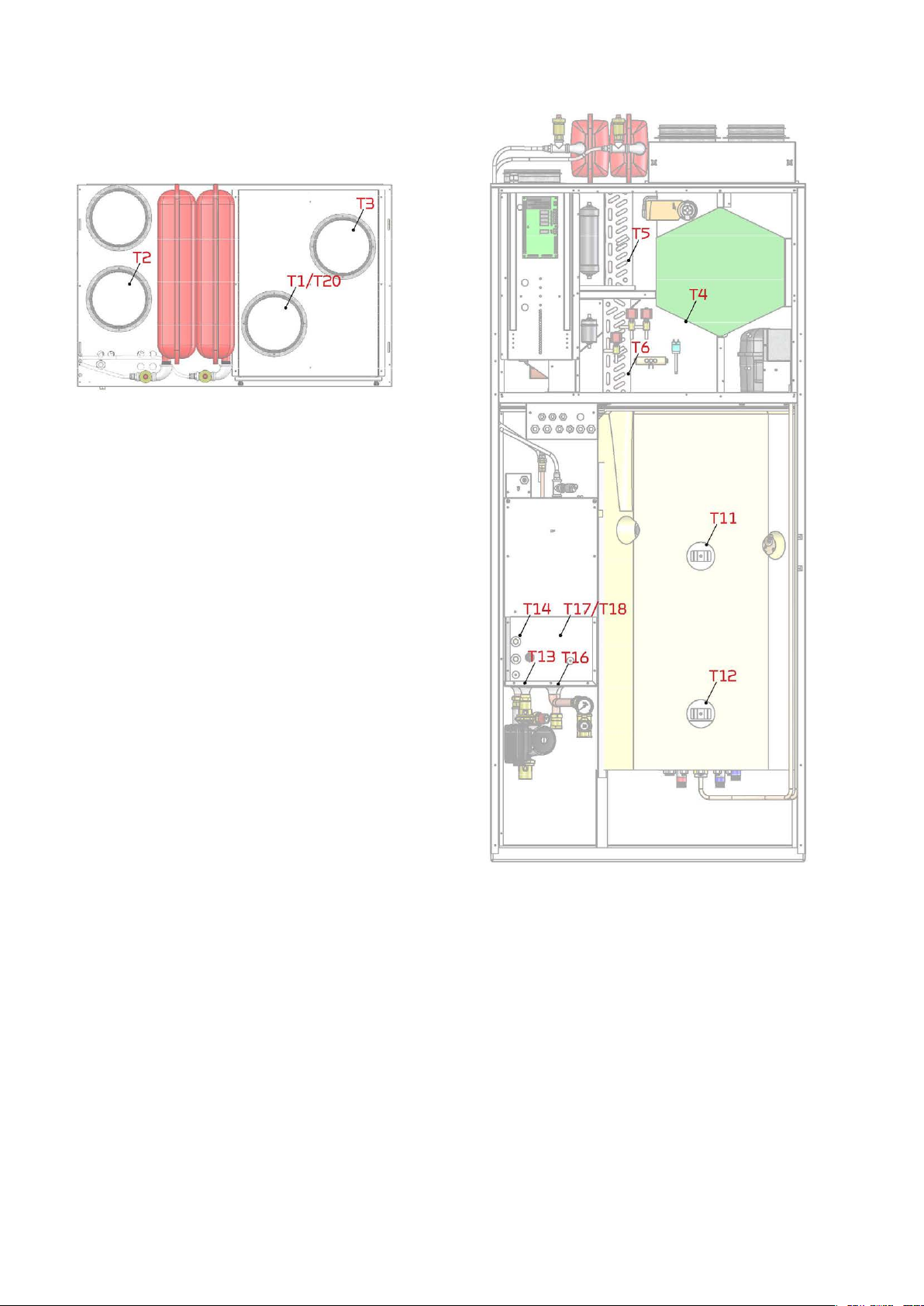
Temperature sensor overview ...........................................................................................................................................................8
Dimensional drawing ............................................................................................................................................................................9
Pipe diagram ....................................................................................................................................................................................... 10
Accessories ................................................................................................................................................................................................ 11
Electrical pre-heating element for frost protection of the unit ................................................................................................ 11
CO2-sensor ......................................................................................................................................................................................... 11
EM-box ................................................................................................................................................................................................. 11
Safety group ....................................................................................................................................................................................... 11
Safety group with scalding protection ........................................................................................................................................... 11
Vibration absorbers .......................................................................................................................................................................... 12
Flexible sound damper ...................................................................................................................................................................... 12
Pollen filter .......................................................................................................................................................................................... 12
Trolley .................................................................................................................................................................................................. 12
SHW hot water tank ........................................................................................................................................................................... 12
Installation
Assembly .................................................................................................................................................................................................... 13
Transport into the dwelling .............................................................................................................................................................. 13
Positioning of unit .............................................................................................................................................................................. 13
Ground collector circuit ........................................................................................................................................................................... 14
Examples of the laying ...................................................................................................................................................................... 14
Electrical installation
Safety ................................................................................................................................................................................................... 15
Connections overview ...................................................................................................................................................................... 15
User panel .................................................................................................................................................................................................. 16
Touch Panel ......................................................................................................................................................................................... 16
Dimensional drawing user panel ..................................................................................................................................................... 16
Placement of the Touch panel ......................................................................................................................................................... 17
Mounting the wall bracket ............................................................................................................................................................... 18
Electrical connections unit ...................................................................................................................................................................... 19
Power supply ...................................................................................................................................................................................... 19
GEO3, GEO6 and GEO9 ....................................................................................................................................................................... 19
Change from 400V to 230V ............................................................................................................................................................. 20
Circulation pump ................................................................................................................................................................................ 21
Electrical connections accessories ........................................................................................................................................................ 22
SHW hot water tank ........................................................................................................................................................................... 22
User selection 1 .................................................................................................................................................................................. 23
User selection 2 .................................................................................................................................................................................. 23
External pre-heating element ......................................................................................................................................................... 24
CO2 sensor .......................................................................................................................................................................................... 25
Smart Grid ........................................................................................................................................................................................... 27
External underfloor heating control ............................................................................................................................................... 27
Joint alarm ........................................................................................................................................................................................... 28
Cooker hood and EM box .................................................................................................................................................................. 28
Fire protection .................................................................................................................................................................................... 29
External room sensor ........................................................................................................................................................................ 29
External heat supply .......................................................................................................................................................................... 30
Connecting EHD damper ................................................................................................................................................................... 31
BAH Geothermal heater ................................................................................................................................................................... 32
Passive cooling function ................................................................................................................................................................... 33
Plumbing installation
Condensate drain ..................................................................................................................................................................................... 35
Important information ...................................................................................................................................................................... 35
Hot water tank .......................................................................................................................................................................................... 36
Connection overview ........................................................................................................................................................................ 36

3
Connection ...........................................................................................................................................................................................36
Requirements for water quality ......................................................................................................................................................37
Hot water circulation .........................................................................................................................................................................37
Supplementary coil ............................................................................................................................................................................37
Softened water ...................................................................................................................................................................................37
Central heating ..........................................................................................................................................................................................38
Connection overview .........................................................................................................................................................................38
The brine circuit ..................................................................................................................................................................................39
Check list for the central heating system prior to start-up ........................................................................................................40
Plumbing connections for accessories ..................................................................................................................................................41
Safety group ........................................................................................................................................................................................41
Safety group with anti-scald protection ........................................................................................................................................42
Passive cooling module .....................................................................................................................................................................43
Domestic hot water tank ...................................................................................................................................................................44
Connecting to SHW hot water ..........................................................................................................................................................45
Connection to supplementary coil in SHW hot water tank .........................................................................................................46
Connecting to DHW hot water ..........................................................................................................................................................47
Ventilation installation
Duct system ...............................................................................................................................................................................................48
Legislation ............................................................................................................................................................................................48
Ducts .....................................................................................................................................................................................................48
Ventilation unit ...................................................................................................................................................................................48
Extract air ............................................................................................................................................................................................49
Supply air .............................................................................................................................................................................................49
Roof terminals .....................................................................................................................................................................................49
Installation example ...........................................................................................................................................................................49
Balancing ....................................................................................................................................................................................................50
Important information .......................................................................................................................................................................50
Balancing connectors ........................................................................................................................................................................50
Pressure fall diagram .........................................................................................................................................................................50
Start-up
Central heating ..........................................................................................................................................................................................51
Filling with water .................................................................................................................................................................................51
Topping up water ................................................................................................................................................................................51
Check the particle filter .....................................................................................................................................................................51
Troubleshooting
Emergency operation ...............................................................................................................................................................................52
Emergency operation domestic hot water ....................................................................................................................................52
Emergency operation central heating ............................................................................................................................................53
Domestic hot water ..................................................................................................................................................................................54
Errors and solutions domestic hot water .......................................................................................................................................54
Central heating ..........................................................................................................................................................................................54
Errors and solutions central heating ..............................................................................................................................................54

4
General information
Safety
Power supply
Heat pump domestic hot water
The heat pump must undergo suitable service inspections under applicable legislation and regulations to keep it in good condition and
in compliance with safety and environmental requirements.
Responsibility for maintenance of the heat pump rests with the owner/user.
Heat pump for central heating
The heat pump must undergo suitable service inspections under applicable legislation and regulations to keep it in good condition and
in compliance with safety and environmental requirements.
Responsibility for maintenance of the heat pump rests with the owner/user.
CAUTION
Always disconnect the power supply to the unit if an error occurs that cannot be rectified via the control panel.
CAUTION
If an error occurs on electrically conductive parts of the unit, alway contact an authorised electrician to rectify the error.
CAUTION
Always disconnect the power to supply to the unit before opening the unit doors, for instance for installation, inspection,
cleaning and filter change.
CAUTION
Avoid direct contact with the heating system pipes in the heat pump as they can get very hot.
CAUTION
To protect the heat pump against damage, it is fitted with the following safety equipment.
CAUTION
To secure the heat pump against damages, it is fitted with the following safety equipment:
• Expansion systems for central heating and buffertank
• Safety valve for central heating and buffertank
• Low and high pressure switch for compressor

5
Water quality requirements
Requirements for water quality
The hot water tank in the Nilan units is made of steel, which has been given a double enamelling, to ensure an extra long service life. In
addition, the tank is equipped with a sacrificial anode as extra protection. It is important that the sacrificial anode is replaced regularly.
Most units are equipped with an electronic monitoring sacrificial anode, which gives an alarm on the user panel when it is time to
replace it.
In order for the sacrificial anode to function and protect the tank, it is required that the water quality complies with the following:
• Electrical conductivity (EC): Between 30 mS/m and 150 mS/m (millisiemens pr. m) @ 25 °C
• Chloride must be below 250 mg/L @ 65 °C
If the above criteria are not met, the sacrificial anode will not work as intended, after which the tank will be corroded., to
Introduction
Documentation
The following documents will be supplied with the unit:
• Quick guide
• Wiring diagram
In the Quick guide you will find important information regarding installation and start-up of the unit. If you require further information
regarding, for instance, installation of accessories or additional settings in the software, or if you need an extended user manual, the
following documents can be downloaded from the Nilan website:
• Installation instructions
• Software instructions
• User Manual
• Wiring diagram
The instructions can be downloaded from https://www.nilan.dk/en-gb/frontpage/download.
If you have questions regarding installation and operation of the unit after having read the instructions, please contact your nearest
Nilan dealer. A list of Nilan dealers is available on www.nilan.dk/forhandlere.
From factory, the unit has been tested and is ready for operation.
ATTENTION
The unit must be started up immediately after installation and connection to the duct system.
When the ventilation unit is not in operation, humidity from the rooms will enter the duct system and create condensate
water that can run out of the valves and cause damage to floors and furniture. Condensation may also form in the ven-
tilation unit, which can damage its electronics and fans.

6
Unit type
Product description
Compact P is a ventilation unit with heat recovery, that has a built-in heat pump, which is used for the production of domestic hot wa-
ter, and which is also able to heat and cool the home by central heating via a ground source heat pump.
Compact P is designed for air flows of up to 275 m3/h at 100 Pa external counter-pressure. Compact P XL can handle air flows up to
430 m3/h at 100 Pa external counter-pressure.
The unit is primarily used in residential construction such as single-family houses and apartments. It ventilates the home by drawing
out the moist and bad air via valves in e.g. bathrooms, toilet, kitchen and utility room, and introduces fresh outdoor air in via valves in
living rooms such as. living room, bedrooms and family room.
The cold outdoor air is heated via the high-efficiency counterflow heat exchanger by the hot exhaust air. The heat loss that occurs via
heat recovery, the built-in heat pump use to produce domestic hot water. All the energy in the exhaust air is utilized, and you have not
really seen any heat loss that you experience with an ordinary ventilation unit. In case of high hot water consumption, there is a 1.5 kW
electric supplement heater in the hot water tank, which can also be used to heat the water.
In the winter, the built-in heat pump can heat the supply air up to 34 ° C, and thus contribute to heating the home. When the supply air
is heated, at the same time a little heat is deposited in the hot water tank and ensures a constant high hot water temperature.
The heat pump has a reversible cooling circuit, which means that the cooling circuit can be turned and it can cool the supply air in the
summer. Compact P can cool the supply air by up to 10 ° C in relation to the outdoor air. Due to the low air exchange, usually 1/2 time
per hour, it will not act as an air conditioning system. However, when cooling, moisture in the supply air is removed, which results in a
lower humidity in the home. The lower humidity means that it is easier to withstand a slightly higher temperature, which therefore pro-
vides good comfort in the home.
When Compact P cools the supply air, the energy is deposited in the hot water tank, and it can thus be said that “free” domestic hot wa-
ter is produced during those periods.
The energy-efficient and low-noise GEOthermal heat pump heats the home via floor heating or lowtemperature radiators. It retrieves
the energy from the earth. The heat pump has an electrical power supply to help it to function during very cold periods. GEO can cool
the home in the summer with passive cooling, either through the underfloor heating system or fan coils.
The GEO ground source heat pump can also be used to help produce hot water for domestic use, either by pre-heating the water in a
buffer tank, or directly in a Compact P hot water tank, if bought with a solar coil.

7
The unit
Compact P:
1. Duct connections
2. Filter change cover
3. Control panel (Touch-panel)
4. Extract air filter
5. Outdoor air filter (pollen filter is placed here if required)
6. Counterflow heat exchanger
7. Heat pump
8. Automatic CTS700
9. Fans
10. 100% bypass damper
11. Pre-heating element (Polar version only)
12. LAN-cable (for connecting to router or PC)
13. Condensation drain with water lock
14. 180 l domestic hot water tank (DHW)
15. 1,5 kW electrical supplement heater (with overheating cut-
out, which has to be pressed in again if activated)
16. Electronically monitored sacrificial anode
17. Supplementary coil (only SOL version)
18. Plumbing connections
19. Electrical connection panel
20. Emergency mode (domestic hot water)
GEO:
21. 2 x 8 l expansion tank for central heating and brine circuit
22. Safety valve and manometer for the central heating circuit
23. Inverter controlled DC compressor
24. Feed tab and particle filter for the central heating circuit
25. Integrated circulation pump for the brine circuit
26. 2 kW electrical supplement heating

8
Temperature sensor overview
Temperature sensors in the unit
T1: Outdoor air
T2: Supply air
T3: Extract air
T4: Extract air after heat exchanger
T5: Condenser
T6: Evaporator
Temperature sensors outside the unit
T7: Supply air after heating element
(accessory)
T8: Outdoor air before preheating element
(accessory)
T9: On heating element
(accessory)
TExt: External temperature sensor
(accessory)
Temperature sensors in the hot water tank
T11: Top of tank
T12: Bottom of tank
Temperature sensor Brine
T13: Brine supply flow
T14: Brine return flow
Temperature sensors GEO
T16: Before condenser
T17: After condenser
T18: Supply flow central heating
T20: Outdoor temperature
T23: Evaporator temperature

9
Dimensional drawing
Connections:
1. Outdoor air
2. Supply air
3. Extract air
4. Discharge air
Weight: 257 kg.
All listed measurements are in mm.

10
Pipe diagram
* Everything within the red box is Nilan delivery.
1. Evaporator
2. Service valve for low pressure
3. Low-pressure pressostat
4. Compressor
5. High-pressure pressostat
6. Condensor
7. Expansion valve
8. Sight glass with humidity indicator
9. Service valve for high pressure
10. Combi filter
11. Connection 1"
12. Flexihose 1"
13. Filling tap
14. Shut-off valve
15. Dirt filter
16. Safety valve 3,5 bar
17. Manometer (for central heating, not mounted)
18. Ball valve
19. Circulation pump 130 mm
20. Pressure control 0,5/1,1 bar
21. Flexihose 10 mm
22. Expansion tank 8 L
23. Automatic control vent 3/8"
24. Electric cartridge 2 kW
25. Temperature sensor T18
26. Safety valve 2,5 bar (not mounted)
27. Connection 3/4"
28. Overcurrent valve
36. Circulation pump
40. Temperature sensor T13
41. Temperature sensor T14
42. Temperature sensor T16
43. Temperature sensor T17
46. Outdoor temperature sensor T20
ATTENTION
An overflow valve must be installed point 28 in the floor heating circuit, with a circulation pump with fixed speed. Alter-
natively, remove the individual thermostats, to ensure sufficient flow.
Central heating
Supply flow
Cooling module
Return flow
GEO heat pump
Ground collectors

11
Accessories
Electrical pre-heating element for frost protection of the unit
CO2-sensor
EM-box
Safety group
Safety group with scalding protection
If your ventilation unit is not a Polar version with an integral pre-heating element, we recommend that you
purchase an external pre-heating element as frost protection of the ventilation unit.
During prolonged periods of frost, the high efficiency counterflow heat exchanger will ice up. To prevent ice
formation, we recommend that you install an electrical pre-heating element.
The pre-heating element consumes limited energy and it ensures efficient heat recovery without periods of
defrosting the counterflow heat exchanger. You thereby achieve an overall reduction in energy
consumption.
If you want to adjust the fan speed level according to use of the dwelling/building (amount of people), you
can retrofit a CO2-sensor.
You select the CO2-level you want via the control panel. If this level is exceeded, ventilation will increase.
If you want to run the cooker hood via the ventilation unit, in some cases there may be insufficient air for
cooker hood extraction.
If you install an EM-box, you can regulate the extracted air when the cooker hood is in operation, so that less
air is drawn from, for instance, the bathroom and the utility room. This will allow enough air for the cooker
hood to extract sufficiently.
The EM-box is fitted with a metal filter that cleans the air in the cooker hood of grease particles efficiently. It
thereby protects the ventilation unit.
By law, a safety group must be fitted for the cold water connection to the hot water tank.
Nilan offers a safety valve in brass with the following functions:
• Safety valve
• Check valve
• Stop valve
• Drain tab
The control has a software scald protection that ensures that the water in the hot water tank does not
gets too hot.
If you have a large cooling and / or heating need, it may be necessary to deactivate the software scald
protection. The water in the hot water tank can be up to 90 ° C, which is why you need to install a safety group
with scald protection.
If a solar panel is used to heat the domestic hot water via the supplementary coil in the hot water tank, a
safety group with scald protection must be fitted.

12
Vibration absorbers
Flexible sound damper
Pollen filter
Trolley
SHW hot water tank
It is important to ensure that the ventilation unit does not transfer vibrations to the building. The ventilation
unit should therefore be placed on a vibration absorbing material.
Nilan can supply effective vibration absorbers to place under the ventilation unit. They are sold in packs of 4.
To make it esay to service the unit in the future, we recommend that you fit a flexible connection between the
unit and the duct system.
Nilan flexible sound damper absorbs sounds effectively from both the duct system and from roof stacks.
The ventilation unit comes, as standard, with a plate filter to protect the unit.
If the dwelling is used by anybody with, for instance, pollen allergies, you may benefit from purchasing a
pollen filter. This should be placed in the outdoor air intake, which will reduce the pollen count in the dwelling.
A Nilan trolley makes it easy to transport the heavy units into the home, without having to carry out heavy
lifting yourself with the risk of injury.
A set consists of two lifting carts that are fastened on each side of the unit while it is standing on the pallet.
Using the two handles, lift the unit off the pallet and drive it to where it is to be used.
The SHW tank is a Nilan-produced 250 liter hot water tank with built-in solar coil and heat pump supplemental
coil that can be connected to all Compact P solutions.
The SHW tank is prepared for mounting a temperature sensor for external solar heat control. The supple-
mental spiral is intended for solar heating systems with solar collectors of approx. 4 m2.
The steel container is with double enamelling to guarantee a perfect water quality. It comes with a 1.5kW in-
sert heating element as well as an electrically monitored magnesium sacrificial anode, both of which are con-
trolled by the CTS automatics.
The solution is ideal for families with a large consumption of hot water.

13
Installation
Assembly
Transport into the dwelling
Compact P is supplied in one piece on a pallet, packed in cardboard.
You can use Nilan lifting trolley, with which the unit can be lifted directly off the pallet and into the building. If the filter box is removed,
the unit can be manoeuvred through an ordinary door.
Positioning of unit
The unit should be positioned on a level and vibration-free substrate, with good access for servicing and filter change.
The unit is fitted at the factory with 4 lifting straps, one for each top corner.
This makes it possible to lift in the unit with a crane, which is a great advantage if the terrain does
not allow you to drive with a lift truck.
When lifting the units with the supplied straps, these must be at an angle of max. 45°from the
vertical.
ATTENTION
When setting up the unit, consideration must always be given to future servicing and maintenance, therefore a free
space in front of the unit of at least 60 cm is recommended.
ATTENTION
To achieve a proper run-off from the condensate tray, it is important that the unit is installed in level.
ATTENTION
If a screen is mounted over the Compact P, it must be easy to dismantle this.
At the lower rear and sides of the unit, there are punched areas
which can be clipped out, so you do not cuts the holes yourself.
The rear angle iron on the base frame can be removed, allowing the
unit to be pushed closer to the wall, thereby concealing the water
connections.

14
Ground collector circuit
Examples of the laying
By laying the geothermal circuit there are some range distances, which need to be observed to get a unit which will have an effective
and smooth operation. Further local authorities may make requirements for installation and acceptance of the facility before entry
into use.
In some cases where there is less space vertically holes is drilled for hoses, but most lay the hoses horizontally. Below are some
examples of laying the ground collectors.
Example of layout of ground tubes collecting in a well
Example of layout of ground tubes collected within the foundation:
ATTENTION
Is is important to pressure test the pipes for tightness one by one immediately before covering with soil, as during
handling.
Min.
1,5 m
Min. 0,6 m
Min. 0,4 m
Min.
1 m
Min.
1,5 m
Min. 0,6 m
Min.
1 m

15
Electrical installation
Safety
It is important to check that wires are not damaged or squeezed during connection and use.
Connections overview
1. Electrical connection cable for GEO 3/6/9
2. Temperature sensors
3. Connector for additional electric heating in SHW tank
4. Crown sleeve for heat / cooling control (HEAT + COM: heat control. COM + COOL: cooling control)
5. RJ45 connector for T21, T22 and anode in SHW tank
6. Control cable for 3-way valve for SHW container
7. Power supply cable for supplementary electric heating for central heating
8. Power supply cable for circulation pump for central circuit
9. Communication cable for Compact P (control cable between print)
10. Communication cable for GEO 3/6/9 (control cable for GEO)
11. Cable for environmental pressure switch
12. Power supply cable for brine pump
13. Power cable for GEO 3/6/9 + Compact P (main supply cable)
14. Emergency operation of electricity supplement for central heating
15. Power supply socket 230V for Compact P
ATTENTION
All work must be carried out by qualified persons and in compliance with existing legislation and regulations.
ATTENTION
It is important that the power is off, if you do work to the electrical components of the unit.
2 7
9 10 11
3 4 5 61 8
12 13 14 15

16
User panel
Touch Panel
At delivery of the unit, the Touch panel is integrated in the front, but can be moved out, if you want to place it in e.g. the Kitchen or living
room. The Touch panel should be located in a prominent place to allow changes to be made to the settings and for observing operational
warnings or alarms.
Do you want to crimp a RJ45 plug on to a cable, you must notice the following:
Dimensional drawing user panel
ATTENTION
An ordinary Type A (T-568A) LAN-kabel (not a crow over cable) must be used, max 20 m.
1. Green/white
2. Green
3. Orange/white
4. Empty
5. Empty
6. Orange
7. Brown/white
8. Brown
The illustration shows the clip on the back of the connector.
1. Locking clip
2. Power-connection
3. USB stick
Use RJ45 T568 type A plug and RJ45
crimping tool.
Touch panel seen from below.

17
Placement of the Touch panel
Below is shown how the touch panel can be moved out of the unit. The following page shows how to mount the wall bracket for the
Touch panel.
1. Unscrew the two screws at the top of the lid so it can be
removed.
2. At the top is the aperture plate that is intended to block
the hole when the touch panel is removed.
3. The Touch panel is lifted by pressing the lock clamp at the
bottom.
4. Unscrew the cover and hang it next to the hole.
5. Unscrew the Touch panel wires from the circuit board,
remove the wall bracket and mount it where the Touch
panel is to be hung.
6. Route the wire from the Touch panel down into the Com-
pact P, where it is connected to the circuit board.
7. Connect the touch panel as shown in the above diagram,
see accompanying electrical diagram. The blue and blue/
white wires should not be used.
8. Fix the aperture plate to the cover in front of the circuit
board. Re-attach the lid and secure with the two screws at
the top, giving you a nice white surface.

18
Mounting the wall bracket
The Touch panel can be mounted on the wall using the integral wall-bracket.
1. The wall bracket is fixed to the wall with two screws. 2.a. Insert the RJ45 plug into the wall bracket with the top of
the plug aligned with the dotted line in the wall bracket, and
with the RJ45 release tab facing away from the wall.
2.b. You can fit the RJ45 plug to the cable yourself. For this
purpose, a spacer is supplied.
The spacer is attached to the LAN cable which is located
behind the large door.
2.c. The top of the RJ45 plug must be flush with the dotted
line in the wall fitting. The spacer fits between the plug and
the cable relief bracket.
3. The cable may be routed down from the wall fitting or
into a hole in the wall behind it.
4.Push the touch panel down over the wall bracket until a
click is heard.
The panel may be removed from the wall by pressing the
locking clip.
5. The touch panel is ready for use.

19
Electrical connections unit
Power supply
GEO3, GEO6 and GEO9
CAUTION
The power supply is plugged into a 230V socket with a safety switch. It is important that the unit has ground connection.
The ventilation unit is supplied with an EU Schuko plug for 230V
power supply.
This means that if you have not installed a shoko socket with
side earth or pin earth, an Adapter schuko plug with pin earth
must be used.
This Schuko adapter can be plugged into the ventilation unit's
Shuko plug and then into a socket with earth.
Schuko socket
with side earth
Schuko socket
with pin earth
Adapter Schuko
plug with pin
ground
Common connection for Compact P
and heating pump for central heating
Standard:
3 x 400V, 3L+N+PE, 16 A, 50 Hz
(Schuko plug)
Remember safety switch
Power connection for Compact P, ventilation and domestic hot water
This power connection via Schuko socket allows to measure the power consumption
of the ventilation separately, as well as the possibility that the hot water part does
not have the same connection as the heat pump.

20
Change from 400V to 230V
The standard connection in the unit is 3 x 400V + N. In those countries or areas where this standard is not applicable, the unit can easily
be switched to either 3x230V or 1x230V.
The terminal block can be found in the control for GEO. Please refer to the wiring diagram enclosed with the unit.
3 x 400V + N
1. Jumper located in L1+L1+L1
(top clamping row)
2. Jumper located in N + zero
on the right (bottom clamping row)
3. Black wire located in V
(bottom clamping row)
4. Blue wire located in N
(bottom clamping row)
3 x 230V
1. Jumper located in L1 + L1 + L2
(top clamping row)
2. Jumper located in W + N
(bottom clamping row)
3. Black wire located in zero to the right of N
(lower clamping row)
4. Blue wire disconnected and
secured with crown sleeve
1 x 230V
1. In the panelboard there must be mounted
a 3x16A circuit breaker.
There must be 40A available before the
circuit breaker.
2. Wires are connected between the termi-
nal block and the circuit breaker:
U = brown, V = black,
W = gray, N = blue/zero.
3. Jumpers are mounted on the access side
of the circuit breaker from 1-2 and 2-3.
4. Brown (L1) is mounted in the third wire
inlet.
Blue/zero (N) is mounted in the fourth wire
inlet.
ATTENTION
The installer carries the responsibility for the electrical installation work.
This manual suits for next models
2
Table of contents
Other nilan Heat Pump manuals

nilan
nilan CTS700-TOUCH Compact P GEO User manual

nilan
nilan Compact P User manual

nilan
nilan Compact P Polar EK 6 kW CTS 700 Mounting instructions

nilan
nilan VGU 180 EK RS User manual

nilan
nilan Compact P Mounting instructions

nilan
nilan Comfort 600 User manual

nilan
nilan Compact P Polar EK 6 kW CTS 700 Instruction Manual

nilan
nilan Compact P User manual
Popular Heat Pump manuals by other brands

STIEBEL ELTRON
STIEBEL ELTRON WPL 19 A Operation & installation

Payne
Payne PH3G----A Product data

Daikin
Daikin MHC Installation & maintenance data

York
York YACT038-072 installation manual

Econar
Econar GeoSource DualTEK GV Series Installation and operating instructions

Amana
Amana RHE60A2A Specification sheet