Nilar Ferroamp Home Box User manual
21‐0001&21‐0002

DocumentID:73‐H006.Copyright©NilarAB.Allrightsreserved.
ThankyouforpurchasingaNilarproduct!Itisrequiredtoreadandunderstandtheseinstructionscarefullyforasafer
installationandoperation,aswellasoptimumperformanceandalongerservicelife.
Keepthismanualinasafeplaceforfuturereference.
Thismanualmaybemodifiedandupdatedwithoutpriornotice.ContactNilarforvalidation.
Colorsusedinillustrationsofe.g.cablesareonlyillustrativeandmightdeviatefromtheactualcolor.
WithoutwrittenpermissionfromNilarthismanualisnottobecopiedortransferredforotherpurposes,neitherinits
entiretynorpartsofit.
TheproductdescribedinthismanualismanufacturedincompliancewiththeLowVoltageDirective(LVD)2014/35/EU,
theElectromagneticCompatibility(EMC)Directive2014/30/EUandtherestrictionsofcertainhazardoussubstances
accordingtoRoHSDirective2011/65/EU.
TheproductcontainsnickelmetalhydridebatterypacksthatfollowtheEU‐directive2006/66/EG(‘BatteryDirective’).The
batterypacksdonotcontaintheheavymetalslead,mercuryorcadmium.
TheproductadherestotheWasteElectricalandElectronicEquipment(WEEE)Directive2012/19/EU.Thismeansthatthe
manufacturer/importerhasaresponsibilitythatthemanufacturedproductsarecollected,takencareofandrecycledafter
theyhavereachedtheendoftheirlifespan.
NilarproductsareincompliancewithRegulation(EC)No.1907/2006concerningtheRegistration,Evaluation,
AuthorizationandtherestrictionofChemicals(REACH).WecheckthatoursupplierscomplywithREACHrequirementsfor
allthematerialsandcomponentstheydelivertous.
©NilarAB.Allrightsreserved.
Documentidentification:73‐H006
VersionStatusDate
4.0Previousrelease 2019‐10‐07
4.3Internalrevision2020‐04‐14
5.0Releasedrevision2020‐04‐23

DocumentID:73‐H006.Copyright©NilarAB.Allrightsreserved.
Thismanualwillgiveyouasareaderallthenecessaryinstructionsforamoreprofessionalandsaferhandlingofthe
product.Readthemanualcarefullyinordertoavoidmistakesandrisks.Themanualisdividedintothefollowingchapters:
ChapterContentStartingpage
1.SafetyInformationGeneralsafetyinformation1
2.TechnicalsupportandwarrantyReferences2
3.EnvironmentContent,recycling3
4.FunctiondescriptionGeneraldescriptionofproduct4
5.Transportation,liftingand
storage
Instructions,conditions10
6.InstallationInstructionsforinstallation14
7.OperationChecklist31
8.MaintenanceRecommendations,schedules32
9.DecommissioningInstructions,references33
10.TroubleshootingInstructions34

DocumentID:73‐H006.Copyright©NilarAB.Allrightsreserved.
Belowfollowsanexplanationwhichfacilitatestheunderstandingofabbreviationsusedthroughoutthemanual.
AbbreviationSignification
ACAlternatingCurrent
BMS BatteryManagementSystem
CANControllerAreaNetwork
DCDirectCurrent
EDSElectronicDataSheet
EMCElectromagneticCompatibility
EMSEnergyManagementSystem
ESOEnergyStorageOptimizer
IMUIntegratedMonitoringUnit
LEDLightEmittingDiode
LVDLowVoltageDirective
MCBMiniatureCircuitBreaker
MSDSMaterialSafetyDataSheet
NiMHNickelMetalHydride
PLCProgrammableLogicController
PPEPersonalProtectiveEquipment
PSNProperShippingName
RCDResidual‐CurrentDevice
REACHRegistration,Evaluation,AuthorizationandtherestrictionofChemicals
RoHSRestrictionsofHazardousSubstances
SoCStateofCharge
VDCVoltofDirectCurrent
WEEEWasteElectricalandElectronicEquipment

DocumentID:73‐H006.Copyright©NilarAB.Allrightsreserved.
Tableofcontents
1. SafetyInformation..............................................................................................................................1
1.1 Safetymarkingsinthisinstruction...................................................................................................................1
1.2 Generalwarningsandcautions.......................................................................................................................1
2. Technicalsupportandwarranty........................................................................................................2
3. Environment.......................................................................................................................................3
3.1 Compliance......................................................................................................................................................3
3.2 Cabinet............................................................................................................................................................3
3.3 BatteryManagementSystem(BMS)................................................................................................................3
3.4 Batterypack.....................................................................................................................................................3
3.5 IntegratedMonitoringUnit(IMU)...................................................................................................................3
4. Functiondescription...........................................................................................................................4
4.1 Generalschematicoverview............................................................................................................................5
4.2 Systemspecification........................................................................................................................................5
4.3 Measurements.................................................................................................................................................6
4.4 Batterystring...................................................................................................................................................6
4.5 Batterypackspecificationandbuild‐up...........................................................................................................6
4.6 IntegratedMonitoringUnit(IMU)...................................................................................................................7
4.7 ConnectionsIMU.............................................................................................................................................8
5. Transportation,liftingandstorage..................................................................................................10
5.1 Transportation...............................................................................................................................................11
5.2 Movingandlifting..........................................................................................................................................12
5.3 Storage..........................................................................................................................................................13
6. Installation........................................................................................................................................14
6.1 Generalconditionsonsite.............................................................................................................................15
6.2 Scopeofsupply..............................................................................................................................................15
6.3 Placement......................................................................................................................................................16
6.4 Adjustment....................................................................................................................................................16
6.5 Attachment....................................................................................................................................................17
6.6 Dismantlingofcabinetpriortoinstallation...................................................................................................17

DocumentID:73‐H006.Copyright©NilarAB.Allrightsreserved.
6.7 ConnectionofEnergyHubsystempowersupply...........................................................................................19
6.8 Communication.............................................................................................................................................21
6.9 Preparationofconnectionspriortoinstallation............................................................................................22
6.10 Placementofbatterypacks...........................................................................................................................22
6.11Connectionofbatterypacks..........................................................................................................................24
6.12 Assemblyofcabinet.......................................................................................................................................30
7. Operation..........................................................................................................................................31
7.1 Checklistforoperation..................................................................................................................................31
8. Maintenance.....................................................................................................................................32
8.1 Protectivemeasuresduringmaintenance.....................................................................................................32
8.2 Inspectionandmonitoring.............................................................................................................................32
9. Decommissioning.............................................................................................................................33
9.1Temporarilydecommissioning.......................................................................................................................33
9.2Permanentdecommissioning........................................................................................................................33
10. Troubleshooting................................................................................................................................34

DocumentID:73‐H006.Copyright©NilarAB.Allrightsreserved.
Figures
Figure1:IndicationofSerialnumberstickerontheNilarHomeBox........................................................................................2
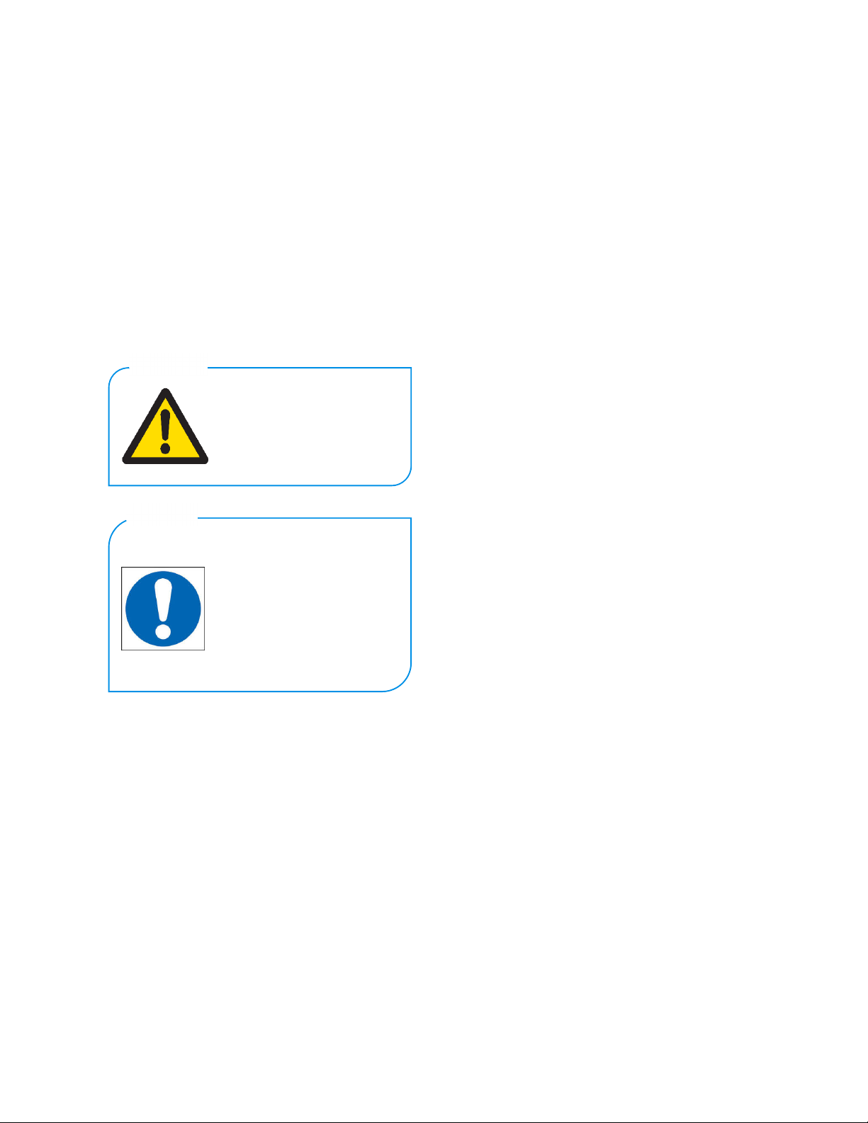
Figure2:NilarHydride®batterypack144VDC(12modules)....................................................................................................4
Figure3:NilarECHomeBox6kWh–Ferroamp.........................................................................................................................4
Figure4:Generalschematicoverview.......................................................................................................................................5
Figure5:HomeBoxunitmeasurements(excl.mountingbrackets)..........................................................................................6
Figure6:Measurementillustrationof144Vbatterypackwithlengthincl.IMU(excl.insulationtray)...................................6
Figure7:144VDCbatterypackwithIMUonfront.....................................................................................................................7
Figure8:Disconnectionofcableconnectors.............................................................................................................................7
Figure9:OverviewofIMUwithcoverlidremoved...................................................................................................................8
Figure10:IndicatedconnectionpointsofIMU‘1’indicatespin1ofconnection.....................................................................9
Figure11:Orientationofbatterypack.....................................................................................................................................10
Figure12:Batterypackincl.liftingstraps................................................................................................................................12
Figure13:Cabinetwithindicatedliftingpoints.......................................................................................................................12
Figure14:Scopeofsupply........................................................................................................................................................15
Figure15:NilarHomeBoxwithindicatedminimumdistancestoneighboringobjects.........................................................16
Figure16:Indicationofsupportlegs........................................................................................................................................16
Figure17:Mountingbracketsforwallattachment..................................................................................................................17
Figure18:Removalofcoverlid................................................................................................................................................17
Figure19:Dismantlingofcornertops......................................................................................................................................18
Figure20:Beforeandafterremovalofsideplatewithindicatedsuspension........................................................................18
Figure21:Beforeandafterremovaloffrontplatewithindicatedsuspension.......................................................................18
Figure22:Beforeandafterremovaloftopplate....................................................................................................................19
Figure23:BeforeandafterremovalofBMScover..................................................................................................................19
Figure24:LocationofcableentryforFerroampEnergyHubsystempowercableonthebacksideofthecabinet...............19
Figure25:LocationoftheconnectionterminalsforFerroampEnergyHubpowercable.......................................................20
Figure26:Dedicatedterminalforpositive(+)wire.................................................................................................................20
Figure27:Dedicatedterminalfornegative(‐)wire.................................................................................................................20
Figure28:DedicatedterminalforPEwire...............................................................................................................................20
Figure29:Generaloverviewofthecommunicationloop.......................................................................................................21
Figure30:LocationofRJ45portforinternetconnection........................................................................................................21
Figure31:Installedbatterystringsortedaccordingtolabeling..............................................................................................23
Figure32:PlacementofinsulationtrayinHomeBox..............................................................................................................23
Figure33:Beforeandafterplacementofbatterypackinsideinsulationtray........................................................................23
Figure34:Attachedandinstalledbatterypackswithinsulationtrays....................................................................................23

DocumentID:73‐H006.Copyright©NilarAB.Allrightsreserved.
Figure35:BeforeandafterIMUcoverlidremoval..................................................................................................................24
Figure36:InstallationofcurrentsensorcableonIMUofbatterypack‘D’.............................................................................24
Figure37:InstallationofingoingCANopencommunicationcableintoCAN2socketonIMU................................................24
Figure38:InstallationoffanconnectiononIMU.....................................................................................................................25
Figure39:Installationof24VDCpowersupplyconnectiononIMU........................................................................................25
Figure40:InstallationofambienttemperaturesensorconnectiononIMUofbatterypack‘A’............................................25
Figure41:DetailviewofcableentryoncoverlidofIMU........................................................................................................26
Figure42:Installednegative(‐)cable(IMUconnectionsarenotdisplayed)..........................................................................26
Figure43:Installedinterpackcablebetweenbatterypack‘A’and‘B’(IMUconnectionsarenotdisplayed)........................27
Figure44:Installedinterpackcableonpositive(+)terminalforbatterypack‘B’(IMUconnectionsarenotdisplayed).......27
Figure45:Installedinterpackcableonnegative(‐)terminalforbatterypack‘C’(IMUconnectionsarenotdisplayed)......28
Figure46:Installedinterpackcablebetweenbatterypack‘C’and‘D’(IMUconnectionsarenotdisplayed).......................28
Figure47:Currentsensordisplayedwithcorrectinstallationdirection..................................................................................29
Figure48:Installedpositive(+)cableincludingcurrentsensor(remainingIMUconnectionsarenotdisplayed).................29
Figure49:LocationoffuseswithintheBMS............................................................................................................................30
Figure50:WEEEsymbolforseparatedisposal........................................................................................................................33

DocumentID:73‐H006.Copyright©NilarAB.Allrightsreserved.
Tables
Table1:SpecificationforNilarHomeBox..................................................................................................................................5
Table2:Descriptionofvisualsignals..........................................................................................................................................8
Table3:Relationbetweentemperatureandtherecommendedmaximumstoragetimeat75%SoCinitialcapacity..........13
Table4:Denominationtable....................................................................................................................................................15
1.SAFETYINFORMATION
DocumentID:73‐H006.Copyright©NilarAB.Allrightsreserved.
1(34)
1. SafetyInformation
Thischaptercontainsgeneralsafetyinformationthatis
applicabletotheNilarHomeBox.
Toavoidpersonalinjury,donotperformanyservicing
unlessyouarequalifiedtodoso.Refertoallsafety
summariespriortoperforminginstallation,operation,
maintenanceanddecommissioning.Formoredetailed
information,contactNilarandrequesttheMaterial
SafetyDataSheet(MSDS).
1.1Safetymarkingsinthisinstruction
1.2Generalwarningsandcautions
WARNING!
Thisproductcontainspowerfulbatterypacks
(NiMH)andissuppliedbymultiplehazardouselectrical
sources.Bewareofstoredandresidualenergies.
WARNING!
Obeylocalregulationsforliveworkingwhen
casing/doorisopen.
WARNING!
Wearelectricallyinsulatedgloveswhen
handlingbatterypacks.Batterypacksurfacesmaycarry
hazardousvoltageduetoloweredinsulationresistance.
Donotplacebatterypacksonconductivesurfaces.
WARNING!
Riskforelectricshockandarcingifproductis
usedincorrectly.
WARNING!
Thebatterypackscannotbeswitchedoff.
Pleasenote:
Workonlywithonebatterypackterminalatthetime.
Rupturediscmayreleaseelectrolyteduringabnormal
use.Wethereforerecommendwearingsafetyglasses.
WARNING!
Riskforelectricalhazardsifproductis
exposedtorainormoisture.
WARNING!
Donotoperatetheproductwithsuspected
failures.Ifyoususpectthattheproductisdamaged,
haveitinspectedbyqualifiedservicepersonnel.
WARNING!
Donotblockorcovertherupturediscoutlet
onthebatterypack.
WARNING!
Ifafireoccurs,itcanbeextinguishedbyusing
CO
2
.Ensurethatfireextinguishersareavailable.
CAUTION!
Ifthebatterypack(s)isdamaged
mechanically,thefollowingmayoccur:
Highheatgenerationonthesurfaceofthebattery
cells.
Electrolytemayescape.
Eventualsmokefromthebatterypackscanirritatethe
skin,eyesandrespiratorysystem.
Therefore,followtheseguidelines:
Donotopenthebatterypacks.
Donotmodifyormechanicallydamagethebattery
packs.
Donotshort‐circuitthebatterypacks.
Donotcontinuetousethebatterypacksafter
identifiedasfaulty.
CAUTION!
Toavoidpotentialhazards,usethisproduct
onlyasspecified.
CAUTION!
Donotoperatetheproductwithcovers
removed.Ifcoversareremovedduringe.g.repair,do
nottouchanyexposedconnections.
CAUTION!
Theproductshallnotbeexposedtoliquids
(notevendrippingorsplashing)andobjectsfilledwith
liquidsmustnotbeplacedonorclosetotheproduct.
CAUTION!
Removepersonalmetalitemssuchasrings,
bracelets,necklaces,andwatcheswhenphysically
handlingtheproductsinceitcanresultinashort‐circuit
currentcausingsevereburn.
CAUTION!
Keepproductsurfacescleananddry.
Theexclamationmarkwithinan
equilateraltriangleisintendedto
alerttheuserthatnegligenceofthis
informationcanbelifethreatening!
WARNING!
Theexclamationmarkwithina
circleisintendedtoalerttheuser
thatnegligenceofthisinformation
canbeassociatedwithbodily
injuryand/ordamagetothe
product!
CAUTION!

2.TECHNICALSUPPORTANDWARRANTY
DocumentID:73‐H006.Copyright©NilarAB.Allrightsreserved.
2(34)
2.Technicalsupportandwarranty
Regardingtechnicalsupport,pleasecontactyour
authorizedlocalNilarrepresentativeandhavetheserial
numberavailable.
Theserialnumbercanbefoundinfour(4)different
locationsoftheNilarHomeBox,ononeoftheside
plates①,asalosestickerintheplasticpocketforthe
quick‐guide②,onthetopplatebelowthecoverlid③
andonthebackplate④.
①
②
③
④
Figure1:IndicationofSerialnumberstickerontheNilarHomeBox
Regardingthewarrantyconditions,pleasecontactyour
authorizedlocalNilarrepresentative.
Pleasemakesuretoalwayshavethe
serialnumberofyourproduct(s)
availableforwarrantyandtechnical
supportmatters.
CAUTION!

3.ENVIRONMENT
DocumentID:73‐H006.Copyright©NilarAB.Allrightsreserved.3(34)
3.Environment
ThischapterwillinformaboutthecompositionofNilar
productsandhencegivetheuservaluableinformation
onpartlyhowtotreattheproductandpartlyhowitis
recycledthedayithasreachedtheendofitslifecycle.
PleasecontactNilarinordertofindyourclosest
representative.
3.1Compliance
Nilarproductsarecompliantwiththefollowing
directivesandregulations:
EU‐directive2006/66/EC(‘BatteryDirective’).
Thebatterypacksdonotcontaintheheavy
metalslead,mercuryorcadmium.
WasteElectricalandElectronicEquipment
(WEEE)Directive2012/19/EU.
Restrictionsofcertainhazardoussubstances
accordingtoRoHSDirective2011/65/EU.
NilarproductsareincompliancewithRegulation
(EC)No.1907/2006concerningtheRegistration,
Evaluation,AuthorizationandtheRestrictionof
Chemicals(REACH).
3.2Cabinet
Thecabinet(encapsulation)consistsofaluminumand
steelwhichcanberecycledcompletely(apartfromthe
paint).
3.3BatteryManagementSystem(BMS)
TheBMSconsistsofthree(3)variousmaterialtypes.
Themainpartisitsshell/platformwhich,justlikethe
cabinet,ismadefromcarbonsteelandisrecycledas
such.
Thesecondpartiselectronics.Theelectronic
componentsarerecycledaselectronicwaste.
Lastlyitconsistsofvarioustypesofplasticsandhence
recycledassuch.
3.4Batterypack
WhentheNilarbatterypackhasreacheditsendoflife,
Nilartakesthefullresponsibilityfortherecycling
processbyacceptingthecompletebatterypacksback.
Therecyclingprocessusedensuresthatmostofthe
materialsarereusedorrecycledappropriately.The
maincomponentsinthebatterypacksconsistof:
Plastic,aluminum,Ni‐platedsteel,carbonsteeland
activematerials.ContactyourauthorizedlocalNilar
representativeforamoredetailedcomposition
specification.
3.5IntegratedMonitoringUnit(IMU)
TheIMUcanbedividedintotwocategoriesof
materials.Firstthereistheoutershellwhichismadeof
plasticandmustberecycledassuch.Secondlyit
consistsofacircuitboardandthismustberecycledas
electronicwaste.
4.FUNCTIONDESCRIPTION
DocumentID:73‐H006.Copyright©NilarAB.Allrightsreserved.4(34)
4.Functiondescription
NilarHomeBoxisasolutionforgridconnectedenergy
storage.Itcanacceptelectricalenergyfromthegrid,
storetheenergyandprovideenergywhenrequired.
BetweenNilarHomeBoxandthegriditisrequiredto
connecttheFerroamp1EnergyHubwhichconvertsACto
DCandviceversa.Theoperationisfullyautomatedand
monitoredexternallyviatheFerroampEnergyHub
Cloudtool.
NilarHomeBoxcontainsinnovativeand
environmentallyfriendlyNilarHydride®batteries
(NiMH)thatarebasedonabipolarmodularbattery
solution.Themodules,inturn,canbeassembledinto
batterypacksofdifferentvoltages(VDC)inasimple
stackingoperation.Thesebatterypacksarearrangedin
abatterystringconsistingoffour(4)seriesconnected
batterypacks.
Tooptimizeperformance,NilarHomeBoxisequipped
withaBMS.TheBMSmonitorsthestatusofthebattery
packsandcanmanagetheoperationinorderto
optimizeperformance.
TheBMScommunicateswiththeFerroampEnergyHub
viaaCANopencommunicationprotocol.Amongst
othersinformationaboutmaximumallowedchargeand
dischargepower,StateofCharge(SoC),warningsand
alarmsareexchanged.
1SvenskaFerroampElektronikAB,hereinafterreferredtoasFerroamponly
Figure2:NilarHydride®batterypack144VDC(12modules)
Figure3:NilarECHomeBox6kWh–Ferroamp

4.FUNCTIONDESCRIPTION
DocumentID:73‐H006.Copyright©NilarAB.Allrightsreserved.
5(34)
4.1Generalschematicoverview
TheenergyflowinandoutofNilarHomeBoxis
controlledbytheFerroampEnergyHubwhichinturnis
settingtheElectricStorageOptimizer(ESO)power.
TheNilarBMSmonitorsthebatteryenergyflowand
providesthisdatatotheFerroampEnergyHub.
Figure4:Generalschematicoverview
4.2Systemspecification
Table1:SpecificationforNilarHomeBox
DataUnit
Ratedenergy6
kWh
Nominalvoltage,batterystring576VDC
Batterystringvoltagerange480‐768VDC
Nominalvoltage,ESO760VDC
Max.continuouscharging
power6
kW
Max.continuousdischarging
power6kW
Dimensions(HxDxW)
945x
270x
900
mm
Weight(inoperation)207kg
Weight(asfreighted,without
batterypacks)102kg
Weight(withoutbatterypacks)71kg
Protectionclass IP20IP
Max.allowedrelativehumidity
(withoutcondensation)90%
Ambientoperatingtemperature
range‐20to+40
o
C
Pollutiondegree 2Class
OvervoltagecategoryIICategory
EMC
EN61000‐6‐2:2005
(Immunity)
EN61000‐6‐3:2007
(Emission)
IEC
Maximuminstallationaltitude2000m
4.FUNCTIONDESCRIPTION
DocumentID:73‐H006.Copyright©NilarAB.Allrightsreserved.
6(34)
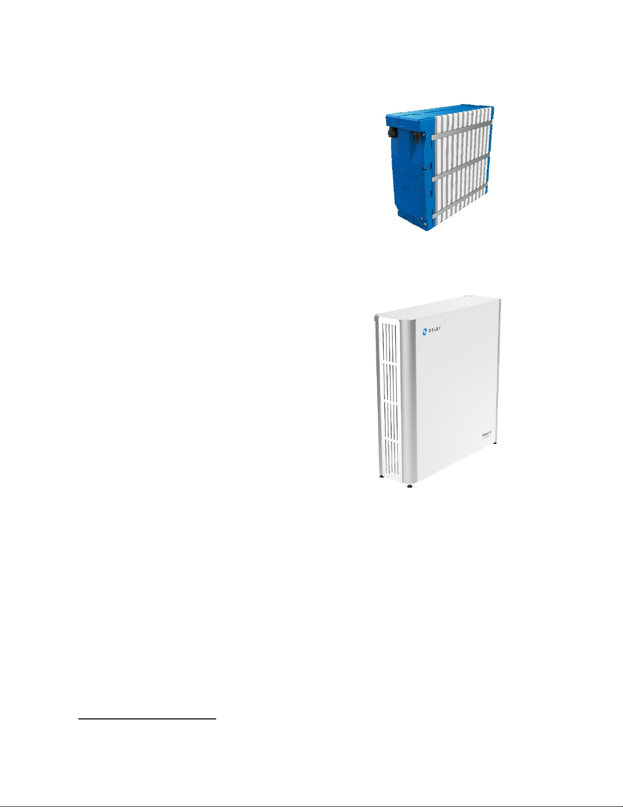
4.3Measurements
TheoutermeasurementsofNilarHomeBoxareas
follows:
Figure5:HomeBoxunitmeasurements(excl.mountingbrackets)
4.4Batterystring
EachNilarHomeBoxcontainsasetoffour(4)battery
packs.Thissetofbatterypacksisreferredtoasa
batterystring.Thebatterypacksareconnectedinseries
tomatchtherequiredsystemvoltage.Thefollowing
componentsarefoundinaNilarHomeBoxbattery
string.
BatterypackswithIMU’s 4pcs
Currentsensor 1pcs
Fanunits4pcs
CANopencables5pcs
24VDCpowercable 4pcs
Stringpowercables 5pcs
Ambienttemperaturesensor1pcs
4.5Batterypackspecificationandbuild‐up
Abatterypackcancontainbetween1and12modules
(12VDCpermodule).InthecontextofNilarHomeBox,
thebatterypacksalwayscontain12moduleseach.
Themaximumbatteryvoltageisobtainedduring
charging,namelywhenthebatterypackisfullycharged.
Formoredetailedinformationregardingthebatterypack,pleaserefer
tothebatterypackmanual(doc.id73‐H001).
Figure6:Measurementillustrationof144Vbatterypackwithlengthincl.IMU
(excl.insulationtray)
945mm
335mm
127mm
306mm
4.FUNCTIONDESCRIPTION
DocumentID:73‐H006.Copyright©NilarAB.Allrightsreserved.
7(34)
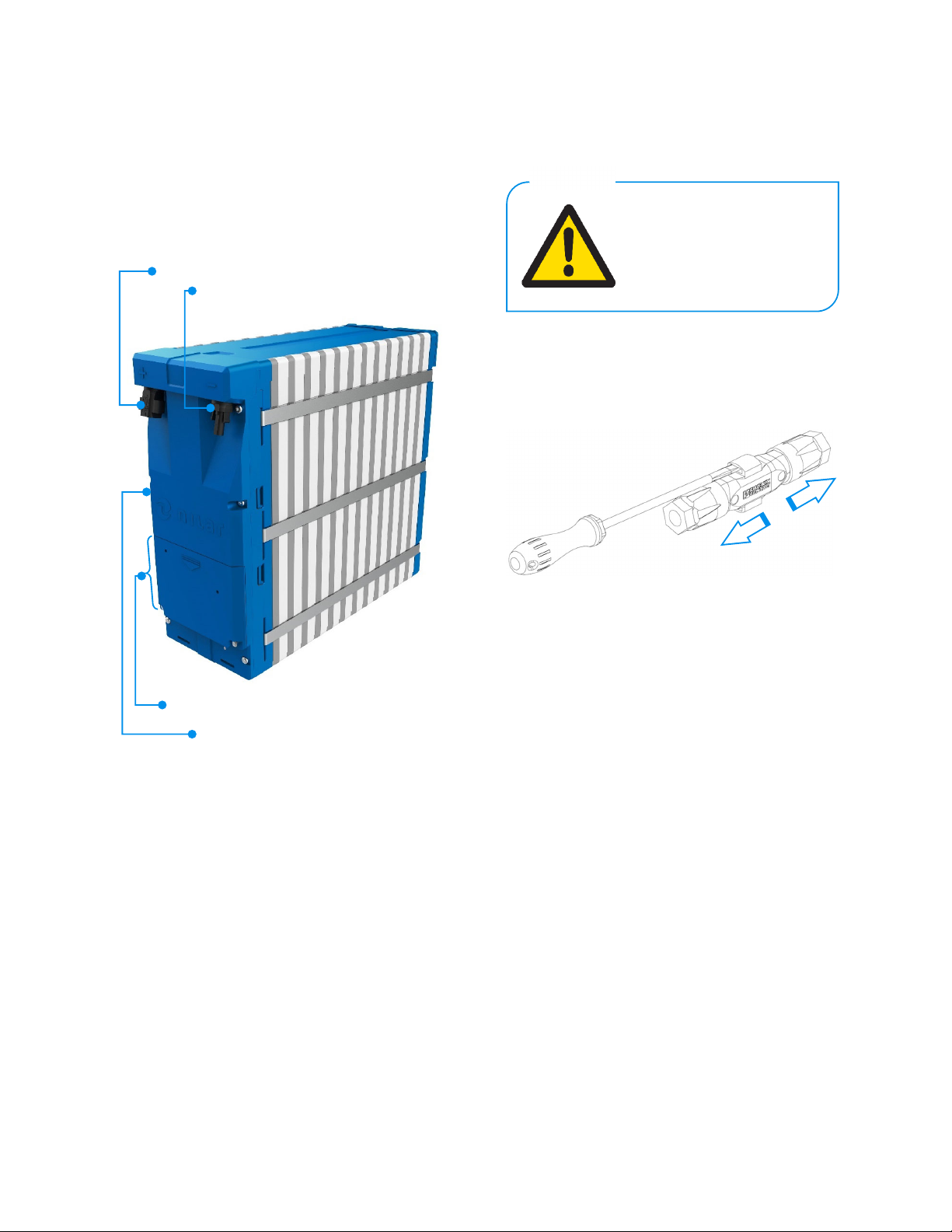
4.6IntegratedMonitoringUnit(IMU)
TheIMUisattachedonthefrontofthebatterypack,
oneIMUperbatterypack.Theunitismonitoringthe
batterypackstatusandcancontrolthebatterypack
fans.ItcommunicatesviaaCANopeninterface.
Positiveterminal(+)
Negativeterminal(‐)
CoverlidforconnectionsofIMU
IntegratedMonitoringUnit(IMU)
Figure7:144VDCbatterypackwithIMUonfront
DatamonitoredbytheIMU:
Modulevoltages(upto12modulesperbattery
pack).
Batterypackvoltage.
Batterypacktemperature(1sensorperbattery
pack).
Batterypackpressure(1sensorperbattery
pack).
Ambienttemperaturesensor(1sensorper
cabinet).
Stringcurrent(1sensorperbatterystring).
ForamoredetaileddescriptionoftheIMU,pleaserefertotheCAN
interfacedescription(doc.Id:SPN‐170063‐88‐H001).
4.6.1Negative(‐)andpositive(+)terminals
Theterminalpostsarelocatedontheuppersideofthe
IMU.
Inordertodetachtheassembledmaleandfemale
connectionaflatscrewdriverisneeded.
Figure8:Disconnectionofcableconnectors
Neverdetachtheassembledmale
andfemaleconnectionduringload.
WARNING!

4.FUNCTIONDESCRIPTION
DocumentID:73‐H006.Copyright©NilarAB.Allrightsreserved.8(34)
4.7ConnectionsIMU
AllconnectionsfortheIMUaretobefoundunderthe
coverlid.
①
②
Figure9:OverviewofIMUwithcoverlidremoved
4.7.1OperationLED(①)
TheoperationLEDindicatesthestatusoftheIMUas
displayedinthefollowingtable.
Table2:Descriptionofvisualsignals
VisualsignalState
●GreenNormalmode(systemmeasuringisactive)
●RedActivealarm
●BluePowersavemode(voltagemeasuring
disabled)
●YellowStart‐upsequence(IMUrequestssettings
inputfromsuperiorcontrolsystem)
AnIMUthatisrunninginnormalmodewillflash:
GreenoffGreenoffetc.
AnIMUthatisrunninginnormalmodeduringstart‐up
sequencewillflash:
GreenYellowGreenYellowetc.
AnIMUinpowersavemodewithnoalarmwillflash:
GreenBlueGreenBlueetc.
AnIMUwithanactivealarmwillreplacethegreen
signalandhenceflash:
RedoffRedoffetc.
AnIMUinthestart‐upsequencewithanactivealarm
willflash:
RedYellowRedYellowetc.
AnIMUinpowersavemodewithanactivealarmwill
flash:
RedBlueRedBlueetc.
4.7.2Resetbutton(②)
BypushingtheResetbutton,theIMUwillbemanually
restarted.
4.FUNCTIONDESCRIPTION
DocumentID:73‐H006.Copyright©NilarAB.Allrightsreserved.
9(34)
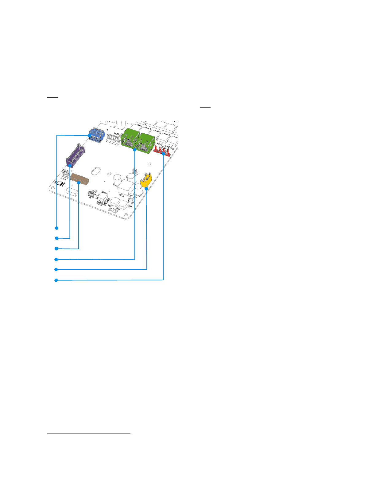
4.7.3Overview‐connections
Thefollowingconnections/switchesareavailableonthe
IMUandtheirfunctionisexplainedinthesubsequent
sections.
Note!Theindicationnumbersinthefollowingfigurecorrelateto
variousheadingsofchapter4.7.
③
④
⑤
⑥
⑦
⑧
Figure10:IndicatedconnectionpointsofIMU‘1’indicatespin1ofconnection
4.7.4Currentsensor(③,blue
●
)
Thisconnectionisforthecurrentsensorwhichmonitors
thecharge/dischargecurrent.
4.7.5Ambienttemperaturesensor(④,purple
●
)
Thisconnectionisusedfortheexternalambient
temperaturesensorthatprovidestheBMSwith
necessarytemperaturedata.Onesensorisusedper
cabinet.
2
Thetwo(2)CANportsareinterchangeable
4.7.6Addresssetting(⑤,brown
●
)
Whenconnectingseveralbatterypackstoforma
batterystring,everybatterypack/IMUrequiresa
uniqueidentification(address).Thisidentificationisset
bytheDIP‐switch.
Note!TheswitchsettingisalreadymadebyNilarpriortodelivery.
4.7.7CAN1andCAN2(⑥,green
●
)
2
TheCANopenconnections(type:RJ45/8P8C)areused
asinputandoutputperbatterypackinordertoconnect
thebatterystringcommunication.
4.7.8Fan(⑦,yellow
●
)
Thisconnectionisusedtopowerthecoolingfanfor
eachbatterypack.
4.7.9PowerIn(⑧,red
●
)
The24VDCpowersupplythatpowerstheIMUis
connectedtotheconnectionmarked‘PowerIn’.
1
1
1
1

5.TRANSPORTATION,LIFTINGANDSTORAGE
DocumentID:73‐H006.Copyright©NilarAB.Allrightsreserved.
10(34)
5.Transportation,liftingandstorage
ThischapterdealswiththeconditionsthatNilar
productsrequirewhenbeingtransported,moved,lifted,
andstored.
Thebatterypacksmustalwaysbeplacedinanupright
position(withtheterminalsinupperposition)during
transportationandstorage:
Figure11:Orientationofbatterypack
Alwaystransportand/orstorethe
batterypacksoninsulating(non‐
conductive)surfaces.
WARNING!
Pleasemakesurethatthebattery
packsarepositionedinthecorrect
wayduringtransportationand
storage.
CAUTION!
AlwayswearPPE(Personal
ProtectiveEquipment)when
handlingbatterypacks.At
minimumthisincludes:
Safetyglasses,safetyshoeswith
steeltoeandelectricallyinsulated
gloves.
CAUTION!
5.TRANSPORTATION,LIFTINGANDSTORAGE
DocumentID:73‐H006.Copyright©NilarAB.Allrightsreserved.
11(34)
5.1Transportation
WhentransportingNilarproducts,somepreparations
andprecautionsmustbetakenwhichwillbedescribed
inthispartofthechapter.
5.1.1Packagingandoutsideconditions
Nilarproductsaredeliveredwell‐protectedintheir
originalpackaging.Nevertheless,transportdamagescan
occur.Therefore,alwayscheckforanyvisibledamage
andsignsofelectrolyteleakage(especiallyatthe
rupturediscoutlet).
Ifanytransportdamageisdiscovered:
Documentthedamage.
Reportthedamagetotheresponsiblelogistic
company.
ContactyourauthorizedlocalNilar
representative.
Ifundamaged,weadvisetokeeptheoriginalpackaging
forfurtherandfuturetransportation.Ifthisisnot
possible,pleasecontactyourauthorizedlocalNilar
representative.
Transportconditionsrangebetweenthetemperatures
−30°Cand+60°Candarelativehumidityupto90%
(withoutcondensation).
Note!Therelationbetweentemperatureandtherecommended
maximumstoragetimeasdescribedinsection5.3isalsoapplicablefor
longertransportationdurations.
5.1.2TransportationofBatterypacks
NilarbatterypacksdonotrequireUNapproved
packagingormarkingwhentransportedbysea,road,
railorair.
Nodangerousgoodsdocumentationisrequiredwhen
transportingNilarbatterypacksbyroadorrail.
Adangerousgoodsdeclarationisrequiredifbattery
packsaretransportedbyseainquantitiesofover100
kginonetransportunit.Nilarbatterypacksarethen
definedasdangerousgoods,class9.UNnumberand
ProperShippingName(PSN)areUN3496andBatteries,
NickelMetalHydride,respectively.
AnAirWaybillorsimilarisrequiredifbatterypacksare
transportedbyair.Nilarbatterypacksarenotclassified
asdangerousgoodsandbelongtotheentryBatteries,
dryinthelistofdangerousgoodsinIATA(noUN
number).IfanAirWaybillisused,thewords‘Not
Restricted’andtheSpecialProvisionnumber(A123)
mustbeincludedinthedescriptionofthesubstanceon
theAirWaybill,accordingtoIATA‐DGR.
Thebatterypacksmustbeseparatedfromeachother
topreventshort‐circuitsandbesecurelypackedto
preventmovementthatcouldleadtoshort‐circuits;
Nilar’soriginalpackagingensuresthatthiscannotoccur.
Pleaseobservethatspecialregulationsapplyfor
defectiveordamagedbatterypacksthathavethe
potentialofleadingtoahazardouseventduring
transportation.PleasecontactlocalexpertiseorNilar
foradviceregardingtransportofdamagedordefective
batterypacks.
5.1.3TransportationoftheNilarHomeBoxcabinet
RegardingtheNilarHomeBoxcabinetitself,nospecial
preparationsorprecautionsareneededotherthan
describedinsection5.1.1Packagingandoutside
conditions.
Whenperformingthevisual
inspection,itisimportantnotto
removethebatterypacksfromtheir
originalNilarsealedplastic
packaging.
CAUTION!
Itisimportanttoalwayspackthe
batterypacksintheiroriginalNilar
sealedplasticpackagingwith
moistureabsorbentbags,ifbeing
transported.
CAUTION!
Table of contents
Popular Portable Generator manuals by other brands


Champion Power Equipment
Champion Power Equipment 100565 Operator's manual

Good Will Instrument
Good Will Instrument GFG-8020H manual

Ametek
Ametek MX Series user manual

Westerbeke
Westerbeke 26.0 KW-50Hz Operator's manual

Vante
Vante 4600 instruction manual

Champion
Champion 46514 Owner's Manual and Operating Instructions