Good Will Instrument GFG-8020H User manual

-~
ARTISAN
®
~I
TECHNOLOGY
GROUP
Your definitive source
for
quality
pre-owned
equipment.
Artisan Technology
Group
Full-service,
independent
repair
center
with
experienced
engineers
and
technicians
on staff.
We
buy
your
excess,
underutilized,
and
idle
equipment
along
with
credit
for
buybacks
and
trade-ins
.
Custom
engineering
so
your
equipment
works
exactly as
you
specify.
•
Critical
and
expedited
services
•
Leasing
/
Rentals/
Demos
• In
stock/
Ready-to-ship
•
!TAR-certified
secure
asset
solutions
Expert
team
ITrust
guarantee
I
100%
satisfaction
All
tr
ademarks,
br
a
nd
names, a
nd
br
a
nd
s a
pp
earing here
in
are
th
e property of
th
e
ir
r
es
pecti
ve
ow
ner
s.
Find the Instek GFG-8020H at our website: Click HERE

DIGITAL FUNCTION GENERATOR
MODEL:
GFG-802011
SAFETY TERMS
AND
SYMBOLS
These terms may appear in this manual or on the product:
WARNING. Warning statements identify condition or practices that
could result in injury or loss of life.
CAUTION. Caution statements identify conditions or practices that
could result in damage to this product or other property.
The following symbols may appear in this manual or on the product:
DANGER DANGER ATTENTION Protective Earth(ground)
High Voltage Hot Surface refer to Manual Conductor Terminal
Terminal
Artisan Technology Group - Quality Instrumentation ... Guaranteed | (888) 88-SOURCE | www.artisantg.com

LUlY
1
LlY
13
SECTION
1
GENERAL DESCRIPTION
Page
introduction
..
...
...
.
..
.
....
.
.
.
.
...
...
..
...
1
Front Panel
..........
..........
...............
1
Rear Panel
..................................
..
1
Printed Circuit Boards
.......
............
2
Electrical Description..
....
.
.
.
....
.
.....
2
Specification..
.
.
.
..
..
.
.
.
.
.
...
.
..
..
..
..
.
....
3
SECTION
2
INSTALLATION AND OPERATION
Unpacking andInspection
.
..
.
.
.
....
.
...
5
AC Power Requirements
...............
5
Fuse Replacement..
.
.
.:
..
.
.
...
.
...
..
.....
.
5
Controls and Indicators
...............
5
First Time Operation Procedure
.
.
.
.
10
SECTION
3
THEORY OF OPERATION
General..
.
....
.
..
.
.
.
.
...
....
.
.
.
.
...
.
.
.
.
.
.
...
.
..
.
.
..
.....
.
.
.
..
.
Power Supply
....
.........
.........
.............
............
Frequency Controls Circuit
...................
.........
Constant Current and Triangle Wave Circuit..
.
The Formation Circuit of Square wave and
Sinewave..
.
.
.
..
..
.
..
.
.
.
.
...
.
.
..
.
..
..
..
.
..
.
.
.
....
.
.
.
.
.
.
.
.
......
Power Amplifier..
.
.
....
.
.
..
..
.....
.
..
.
.
.
.
.
.
..
.
.
..
.
.
.
.
.
.
.
.
,
.
.
Circuit of Frequency Counter
.......
...................
SECTION 4 MAINTENANCE
Fuse Replacement
...............
.
.............
..
..........
Cleaning..
.
....
.
.
..
.
.
..
...
..
.
.
.
..
.
.
.
.
...
.
.
.
.
.
.
..
.
.
...
.
.
.
.
.
.
..
.
.
Page
13
13
14
14
16
19
19
2
0
2
0
A
WARNING. For continued fire protection. Replace fuse only with 250V fuse of the specified type and rating, and
disconnect the power cord before replacing fuse.
ENVIRONMENTCONDITION
!
WARNING. To avoid electrical shock, the power cord protective grounding conductor must be connected to ground
n
Operation Environment
:
Indoor use
:
Altitude up to 2000m
:
Ambient Temperature
0°C
to 40°C
:
Relative Humidity 80%(maximum)
:
Installation Category
I1
:
Pollution Degree
A
CAUTION. To avoid damaging the instrument, don't use it in
a
place where ambient temperature exceeds
40°C.
StorageTemperature
&
:
-10°C to 70°C
Humidity
:
70% (maximum)
A
CAUTION
.
To avoid damaging the instrument, V.C.F. (V.C.G.)do not input more than DC15V
NOTE
Artisan Technology Group - Quality Instrumentation ... Guaranteed | (888) 88-SOURCE | www.artisantg.com

SECTION
1
GENERAL DESCRIPTION
INTRODUCTION
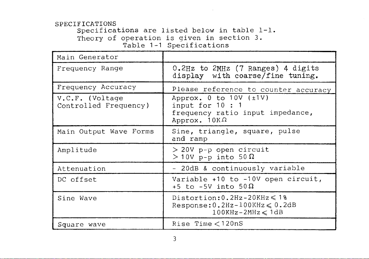
The DIGITAL FUNCTION GENERATOR provides square, triangle,
sine, ramp and pulse waveforms over a frequency range from
0.2
Hz
to
2
MHz,
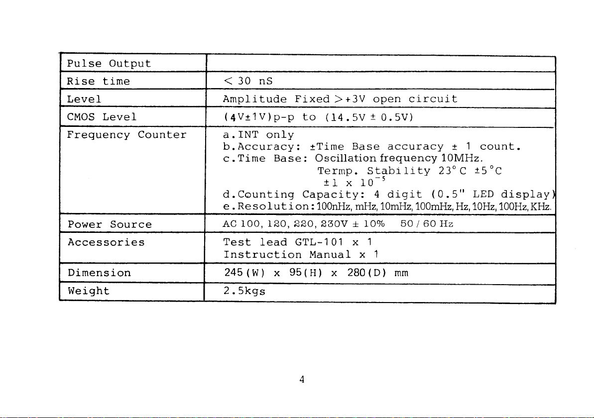
plus a VCF input, variable DC offset and TTL or
CNOS
pulse output.
The built-in frequency counter for measuring internal
oscillation frequency.
FRONT PANEL
The main output and all controls are located on the front
panel. They are: the push button POWER switch, seven frequency
RANGE push button switches, three push button FUNCTION switches,
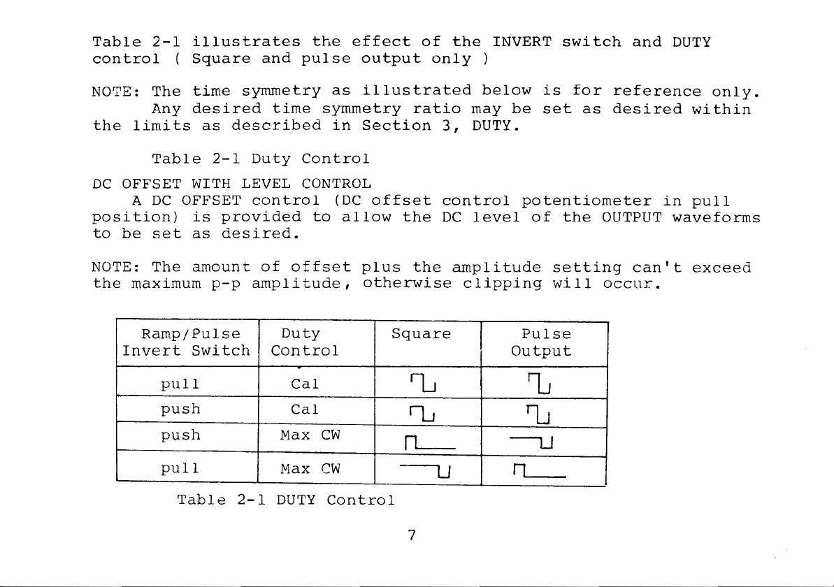
frequency MULTIPLIER (variable), DUTY potentiometer with invert
switch, DC OFFSET control with level control, output
AMPLITUDE
control with output attenuation, OUTPUT,VCF (voltage controlled
frequency) input, TTL or CMOS pulse output, CMOS level control
with CMO,C/TTL selector SW, counter display,
M.k.m.
and
Hz
indicato~,
Gate signal indicator.
REAR PANEL
On
the rear panel is located the power cord receptacle.
Artisan Technology Group - Quality Instrumentation ... Guaranteed | (888) 88-SOURCE | www.artisantg.com

PRINTED CIRCUIT BOARDS
Main Generator:. All circuitry and the power supply are
contained on the main P.C. board. All controls and the POWER
switch are also contained on the main P.C. board.
FREQUENCY COUNTER: The frequency counter is contained on the
main P.C.board.
ELECTRICAL DESCRIPTION
The DIGITAL FUNCTION GENERATOR utilizes two constant current
sources of opposite polarity for charging and discharging a timing
capacitor to produce the trianjlar waveform.
A sinewave shaping network shapes the triangle to produce the
low-distortion sine wave. The level detector senses the voltage
on the timing capacitor and connects and disconnects the current
sources alternately. The square wave produced by the level
detector is utilized to produce the output square wave.
Artisan Technology Group - Quality Instrumentation ... Guaranteed | (888) 88-SOURCE | www.artisantg.com

SPECIFICATIONS
Specifications are listed below in table 1-1.
Theory of operation is given in section
3.
Table
1-1
Specifications
Main Generator
I
Frequency Range
0.2Hz
to
2MHz
(7
~anges)
4
digits
display with
coarse/fine
tuning.
Frequency Accuracy
V.C.F. (Voltage
Controlled Frequency)
Main Output Wave Forms
Amplitude
Attenuation
Please reference
tc
counter accuracy
Approx. 0 to 10V
(+1V)
input for 10
:
1
frequency ratio input impedance,
Approx. 10Kn
Sine, triangle, square, pulse
and ramD
>
20V p-p open circuit
>
10V p-p into
50
R
-
20dB
&
continuously variable
Sine Wave
Square wave
Variable +10 to -lOV open circuit,
+5 to -5V into 50!2
Rise Time
<
1
20nS
Artisan Technology Group - Quality Instrumentation ... Guaranteed | (888) 88-SOURCE | www.artisantg.com

I
Rise time
I
<
30 nS
I
Accessories
Level
CMOS Level
Frequency Counter
Power Source
Test lead GTL-101 x
1
Instruction Manual
x
1
Amplitude Fixed >+3V open circuit
(4V+lv)p-p to
(14.5V
+
0.5V)
a.INT only
b.Accuracy: +Time Base accuracy
+
1
count.
c
.
Time Base
:
Oscillation frequency
10MHz.
Termp.
Stability
23°C
+5"~
+I.
x
d.Counting Capacity:
4
digit (0.5" LED display
e
.
Resolut
i
on
:
100nHz,mHz,IOniHz,lOOmHz,
Hz,
lOHz,100Hz,KHz
AC
100,120,220,230V
i=
1070 50 I60
HZ
Dimension
Weight
*
245(W)
x
%(H)
x
280(D)
mm
2.5kgs
Artisan Technology Group - Quality Instrumentation ... Guaranteed | (888) 88-SOURCE | www.artisantg.com

SECTION
2
INSTALLATION AND OPERATION UPACKING AND INSPECTION
THE DIGITAL FUNCTION GENERATOR is packaged to absorb any
reasonable shock encountered during shipping.
Carefully remove the instrument from the shipping container
and inspect for shipping damage. If damage is found, notify
the carrier immediately.
AC POWER REQUIREMENTS
This instrument operates on line voltages
of
either 100V, 12OV,
22OV,
230V
AC
f
10%
50-60Hz,power dissipation approx. 15VA.
FUSE REPLACEMENT
If for some reason the fuse blows, first try to determine
the cause of the failure and remedy if possible.
NOTE: Replace with the proper size fuse only to prevent damage
to
the instrument.
CONTROLS AND INDICATORS
POWER SWITCH
The power switch applies power to the function generator.
RANGE SWITCH
Seven fixed decades of frequency are provided
by
the RANGE
pushbutton switch. Each of the seven pushbutton RANGE switches
is interlocked. Depressing one pushbutton will release all
others.
Artisan Technology Group - Quality Instrumentation ... Guaranteed | (888) 88-SOURCE | www.artisantg.com

FUNCTION SWITCH
Three interlocking pushbutton switches provide selection
of the desired output waveform. Depressing one switch will
release the switch previously depressed. Square, triangle, and
sine waveforms are provided, satisfying most applications.
MULTIPLIER
The MULTIPLIER is a variable potentiometer allowing frequency
settings between fixed ranges.
DUTY CONTROL WITH INVERT
Time symmetry of the OUTPUT waveforms, as well as the TTL
or CMOS PULSE output, is controlled by the DUTY potentiometer.
When this control is set to the CAL position, the time
symmetry of the output waveforms is
50150
or approximately
100%
symmetrical.
The variable symmetry allows the time period of one-half
the waveform to be changed while the other half remains fixed as
determined by RANGE and MULTIPLIER settings. This unique feature
provides variable pulse width and variable duty cycle pulses.
The duty control potentioneter with INVERT switch when pull
position is provided to invert the time symmetry set by the
Duty control.
Artisan Technology Group - Quality Instrumentation ... Guaranteed | (888) 88-SOURCE | www.artisantg.com

Table
2-1
illustrates the effect of the INVERT switch and
DUTY
control
(
Square and pulse output only
)
NOTE:
The
time
symmetry as illustrated below
is
for reference only.
Any desired time symmetry ratio may be
set
as desired within
the
limits
as described in Section
3,
DUTY.
Table
2-1
Duty Control
DC
OFFSET WITH LEVEL CONTROL
A
DC
OFFSET control
(DC
offset control potentiometer in pull
position)
is
provided to allow the
DC
level of the OUTPUT waveforms
to be set as desired.
NOTE: The amount of offset plus the amplitude setting can't exceed
the maximum p-p amplitude, otherwise clipping
will
occur.
Table
2-1
DUTY Control
Ramp/Pulse
Invert Switch
pull
push
push
pull
Duty
Control
Gal
Cal
Max
CW
Max
CW
Square
Z
'L
L
7
Pulse
Output
Z
7J
U
m--
Artisan Technology Group - Quality Instrumentation ... Guaranteed | (888) 88-SOURCE | www.artisantg.com

Table
2-2
below illustrates the effect of the
DC
OFFSET
control.
The clipped waveform
is
caused
by
too much amplitude and too much
offset.
Offset
Amplitude
Table 2-2
DC
OFFSET Control
Output
0
Max CW
Max CCW
Mid CW
Mid CCW
AMPLITUDE
WITH
ATT
I
I
I
The AMPLITUDE control provides 20dB
of
attenuation of the
output waveform selected
by
the FUNCTION switch. When the switch
is
pull, in addition to 20dB provided
by
amplitude control, a maximum
of
40dB of attenuation, at the output.
Max
Max
Max
Max
Max
V
+1ov
---
ov
---
ov
--h_,
-1ov
/-
+lOV
-
1
OV
+1
ov
b-
-In"
Artisan Technology Group - Quality Instrumentation ... Guaranteed | (888) 88-SOURCE | www.artisantg.com

OUTPUT
Square, triangle, sine, and pulse waveforms are provided
at up to 20V p-p amplitude (open circuit) at the OUTPUT (When
ATT pushbutton switch
is
pushed)
.
The VCF input and PULSE outputs, utilize
BNC
connectors.
VCF INPUT
A
VCF
(
voltage-controlled frequency
)
input
is
provided
for externally sweeping the frequency. Approximately +10V
applied at the VCF input
will
sweep the generator frequency
down to 10:l. The generator may also be swept up in frequency
by applying a negative voltage at the VCF input.
PULSE OUTPUT
The PULSE OUTPUT
is
a TTL or CMOS output signal suitable
for driving TTL or CMOS logic. The rise and fall time of the
PULSE output
is
typically 2511s. The pulse width and repetition
rate may be
set
as desired, utilizing the RANGE and MULTIPLIER
and DUTY control. The symmetry of the PULSE output
is
controlled
in the same manner as the output waveforms described in Table
2-1.
CMOS LEVEL CONTROL
The CMOS LEVEL CONTROL potentiometer (pull position)
provides CMOS LEVEL OUTPUT from 5V to 15V continuously variable.
Artisan Technology Group - Quality Instrumentation ... Guaranteed | (888) 88-SOURCE | www.artisantg.com

PULSE OUTPUT SWITCH
Depress
the
potentiometer switch
and
observe
the
TTL
and
CMOS
output
push
is
TTL,
pull
is
CMOS.
FREQUENCY COUNTER
COUNTER
DISPLAY
LED
indicator
display
measured
inte'rnal
frequency.
GATE LED
Gate
signal
indicates
when
push
the
gate
time switch.
NOTE: Before
applying
power
to
the
Digital FUNCTION GENERATOR,
be
sure
the
proper
line
voltage
is
available.
Plug
the
power
cord
into
the
proper
source
of
11OV.AC 50-60Hz.
All instruments
are
wired
for
llOV
AC
unless
otherwise
order
made.
FIRST TIME OPERATION PROCEDURE
Set
the
digital
function
generator
controls
as
follows:
RANGE-HZ
10K
MULTIPLIER Max. CW
FUNCTION
DUTY
2,
CAL
AMPLITUDE MAX
OFFSET PUSH
ATTENUATOR
0
dB
Artisan Technology Group - Quality Instrumentation ... Guaranteed | (888) 88-SOURCE | www.artisantg.com

MAIN
OUTPUT
Connect an oscilloscope to output.
Observe a 20Vp-p 20KHz (approx.) triangle wave.
FUNCTION
SWITCH
Select and observe a
20V
p-p square wave and sine wave.
AMPLITUDE
CONTROL
Rotate the AMPLITUDE vernier from maximum to minimum and
observe greater than
23dB
of attenuation.
ATTENUATION
Connect the oscilloscope to the OUTPUT and push the
ATT
pushbutton switch that the signal
is
attenuated
by
a factor of
2
0dB.
DC
OFFSET
Reconnect the oscilloscope to the
OUTPUT
and select the triangle
waveform. Rotate the
DC
OFFSET control potentiometer (pull position)
and observe the peaks of the triangle waveform
will
"clip" when the
DC
OFFSET plus the peak amplitude exceeds
Z10V.
Reduce the output amplitude and observe the amount of
DC
OFFSET
may be increased by the same amount the peak amplitude has been
decreased.
Return the potentiometer to "PUSH" position and the
AMPLITUDE
to
maximum.
Artisan Technology Group - Quality Instrumentation ... Guaranteed | (888) 88-SOURCE | www.artisantg.com

DUTY CONTROL
While observing the square waveform on the oscilloscope,
rotate the
DUTY
control
CW
from the CAL positon.
Observe one slope of the square remains constant while the
other slope
is
variable over typically a
10:l
range, producing a
pulse waveform.
INVERT
SWITCH
Depress the
INVERT
potentiometer (pull position) and observe
the positive and negative slopes of the pulse waveform reverse
(invert)
By
selecting the Square wave and repeating the same procedure,
this model DIGITAL FUNCTION
GENERATOR
become very versatile pulse
generators.
The pulse width may be determined by the following formula:
PULSE
WIDTH
=
the reciprocal
of
2
X
freq. setting.
In other words, the pulse width equals one-half the time
period of the frequency set by the
RANGE
and MULTIPLIER controls.
PULSE OUTPUT
Connect the oscilloscope to the PULSE output.
By
adjusting the generator frequency, the
DUTY
control and the
INVERT
switch, the high-speed
TTL
pulse or CMOS pulse may be utilized
as a very versatile pulse generator. With the
INVERT
switch in the
NORM
position, the pulse width "on time"
is
determined by the
RANGE
and
MULTIPLIER setting and the repetition rate "off time"
is
set
by
the
DUTY
control.
Artisan Technology Group - Quality Instrumentation ... Guaranteed | (888) 88-SOURCE | www.artisantg.com

NOTE: When the INVERT switch is set to INVERT, the pulse "off
time" is determined
by
the RANGE and MULTIPLIER setting
and the pulse "on time" is set with the DUTY control.
SECTION 3 THEORY OF OPERATION
GENERAL
This section describes the operation of this DIGITAL
FUNCTION GENERATOR.
POWER SUPPLY
There is two parts for second winding of transformer used
by this function generator. One is 18V AC full wave 300mA, and
the other is 9V AC half wave 300mA. 18V AC rectified
by
BDlOl
&
filtered by C101, C102, then output +24V and -24V (with load).
+24V regulated by UlOl and then get stabilized +15V.
It
will go
through U103 and be regulated to get +5V. Meanwhile it will
be
regulated by Q101 ,U102 to get
-1
5V; by Q102 to get -5V.
In order to prevent work of frequency counter from being
affected
by
the circuit
of
function generator, U104 supplies
independently +5V stable voltage to the circuit of frequency
counter.
Artisan Technology Group - Quality Instrumentation ... Guaranteed | (888) 88-SOURCE | www.artisantg.com

FREQUENCY. CONTROLS CIRCUIT
This unit
is
composed by U201 which controlled frequency
in the instrument, but actually
it
is
achieved by controlling
voltage, V202 which undertakes this mission. U201
is
used for VCF
input invert amp. when VCF input
is
OV,
the
6th
pin of U201
is
also
OV.
If VCF input
is
+10V, the 6th pin
will
gain -13V voltage
and make control voltcge of VR202 controlled by VCF input voltage,
then input control voltage get by VR201, to constant current
generator circuit.
CONSTANT CURRENT
AND
TRIANGLE
WAVE
CIRCUIT
This unit
is
the heart of the instrument.
It
includes constart current
driving circuit U203, Q203, positive current source U204, Q202;
diode switch D201, D202; timing capacitor C203-C207; voltage
follower Q204-9206, differential level detector and flip-flop U301,
negative constant current
is
made
by
U205, Q203, which U203, Q203
is
called as current source.
As
far as U204, U205
is
concerned, U205
is
also called as "constant current driving circuitv.
As
circuit diagram Figure 6-1, differential input of OPA
f
OV,
so
Ve
=
-Vin,
Ie
=
Ic
+
IB;
and IcSIB, therefore
Ie
.i:
Ic.
If
Rc
=
Re
and to add equivalent voltage but contrary polarity
on
it
(
+15V and -15V
),
then
Ic
=
Ie
Vc
=
Ve.
This circuit uses OPA No. UA741, and
its
IE
current
is
only
approximate
O.1UA.
If Ic works within
mA
current range, then
Ic
=
Ie
is
reasonable. Now to change transistor to
FET,
IB
is
in
the staqe of PA
(UUA),
and therefore Vin
=
Ve
=
Vc.
i.e.
to control
not only Vin Voltage but also constant current
Artisan Technology Group - Quality Instrumentation ... Guaranteed | (888) 88-SOURCE | www.artisantg.com

~t
figure
6-2
stated the formation way of triagnle wave.
If
11,
I2
are two groups of constant current source, and
I1
=
212
when
P
point
voltage
is
higher than
A
point voltage, then there
is
a charge current
IA
available
IA
=
I1
-
I2
=
12.
Therefore Vc voltage
will
slowly go
UP
Vin
7i
FIGURE
6-1
Artisan Technology Group - Quality Instrumentation ... Guaranteed | (888) 88-SOURCE | www.artisantg.com

When
P
point voltage
is
lower than
B
point, there
is
I3 current
available and I3
=
11,
i.e.
IA
=
0.
However, I2
is
constant
current source, and
it
permanently needs current source,
therefore, there
is
descharge current
IB
~vailableand
IB
=
12,
so
Vc
voltage
will
slowly come down. Thus come out triangle
waves circulatively.
IK
P
'LOO
Vl -=
11-
___C
Ve
1
K
I
e
V2
-
12-
6%
IB
OVc
FIGURE
6
-
2
-15V
THE
FORMATION CIRCUIT OF SQUARE
WAVE
AND
SINEWAVE
This unit including U401, U302, U303 etc., the formation of
square wave
is
made
by
using
a
flip-flop to produce square form
and phase shift
R318,
R319, R320 are in charge of this mission.
Artisan Technology Group - Quality Instrumentation ... Guaranteed | (888) 88-SOURCE | www.artisantg.com

VR301
is
for fine adjustment of square wave amplitude; R313
is
for TTL output buffer
resistor,
it
can reduce phenomena of
overshoot and ringing. Sinewave
is
made by using triangle wave to
make non-linear amplification, and in the instrument to attenuate
triangle wave in advance. (made by R4O3, and R404) and then make
non-linear amplification, phase shift etc. (made by U401) and again
to input power stage and amplify. VR401
is
to adjust clip point of
sinewave,
i.e.
course adjustment of sinewave distortion. VR403
is
to adjust the symmetry of sinewave,
i.e.
fine adjustment of sine
wave distortion, R405-R407 are "differential state
Re
resistor",
to supply constant current. VR404, R408 are load resistor of
differential output to take resistance and signal output into
positive ratio relation, to adjust VR404 to get the
"GAIN".
Two transistors at the right side of U401 are in charge of the
work of phase shift, because the output of the 8th pin
is
constantly
positive signal source. To adjust VR402 can make U401
its
14th pin
output be zero
D.C.
offset of
A.C.
sinewave. R401, R402 are
decoupling resistor. C401, C402 are decoupling capacitor. R412
supplies
VB
bias.
U303
is
in charge of CMOS level output, and
its
output amplification
is
taken from VR302, then via TTL/CMOS selective switch output to
BNC
at the front panel, while Q301
is
in charge of TTL level to
increase to CMOS level, because (2301 output via collector has
inverter function. Therefore, output at TTL and then via another
AND
GATE to couple the signal here.
Artisan Technology Group - Quality Instrumentation ... Guaranteed | (888) 88-SOURCE | www.artisantg.com
Table of contents
Other Good Will Instrument Portable Generator manuals