Nilfisk-Advance SH SOLAR E User manual

SH SOLAR E, D
Instructions for use
107319182 i (09.2020)
EN-DE-FR-NL-ES-IT-RU-HU-TR-PL-CS

Printed in Hungary
Copyright © 2020 Nilfisk A/S
Instructions for use ........................................................................................................... 3 - 32
Betriebsanleitung.............................................................................................................. 33 - 62
Manuel d’Instructions........................................................................................................ 63 - 93
Gebruikershandleiding...................................................................................................... 94 - 123
Manual de instrucciones................................................................................................... 124 - 154
Manuale di istruzioni......................................................................................................... 155 - 184
Руководство..................................................................................................................... 185 - 214
Üzemeltetési útmutató...................................................................................................... 215 - 242
Kullanma talimatları.......................................................................................................... 243 - 272
Instrukcje dotyczące obsługi............................................................................................. 273 - 302
Návod k obsluze............................................................................................................... 303 - 332

3
SH SOLAR E, D
Original Instructions
Index
1 Safety Precautions and Warnings ................................................................................................4
2 Description .....................................................................................................................................5
2.1 Application................................................................................................................................5
2.2 Operation elements ..................................................................................................................5
3 Installation ......................................................................................................................................5
3.1 Temperature conditions ............................................................................................................5
3.2 Condition of distance................................................................................................................6
3.3 Mounting of feet and levelling of machine ................................................................................6
3.4 Mounting of handle...................................................................................................................6
3.5 Mounting of spacers .................................................................................................................6
3.6 Water connection......................................................................................................................7
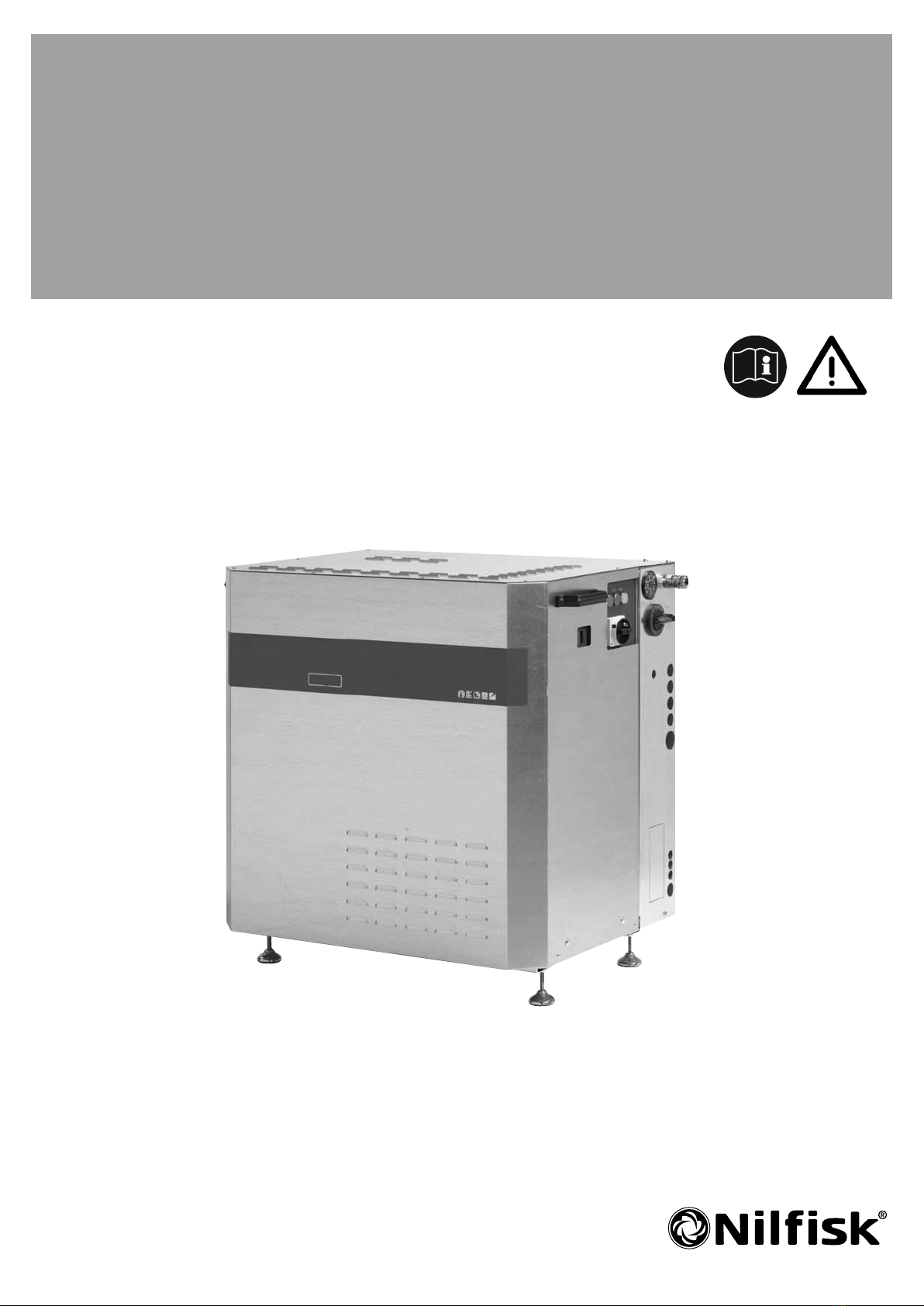
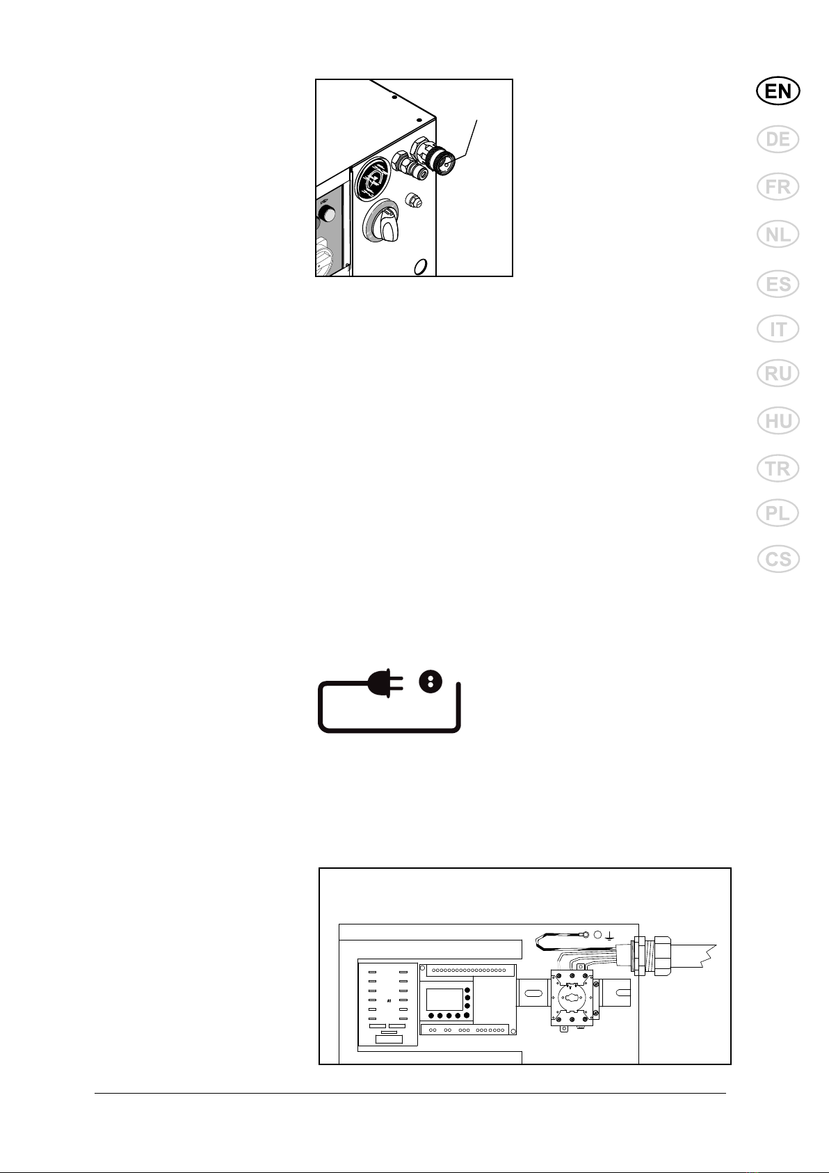
3.7 Mains power connection...........................................................................................................7
3.8 High pressure connection ........................................................................................................8
3.9 Venting (D models) ...................................................................................................................9
3.10 Venting - E models ................................................................................................................10
3.11 Connecting to external fuel supply – D-models .....................................................................11
4 Operation ......................................................................................................................................12
4.1 Connections............................................................................................................................12
4.2 Operation................................................................................................................................15
5 Fields of Application and Working Methods..............................................................................19
5.1 Fields of application................................................................................................................19
5.2 Working pressure ...................................................................................................................19
5.3 Temperature ..........................................................................................................................19
5.4 Mechanical impact..................................................................................................................19
5.5 Detergents..............................................................................................................................20
5.6 Working methods....................................................................................................................21
5.7 Typical cleaning tasks.............................................................................................................22
6 Maintenance .................................................................................................................................23
6.1 Hour counters.........................................................................................................................24
6.2 Oil ...........................................................................................................................................24
6.3 Water filter ..............................................................................................................................25
6.4 Cleaning of high pressure nozzle ...........................................................................................25
6.5 Fuel filter - D-models only.......................................................................................................25
6.6 Disposable waste ...................................................................................................................25
7 Trouble Shooting..........................................................................................................................26
7.1 General trouble shooting - all models.....................................................................................26
7.2 Errors messages, E (electrical heated) models......................................................................27
7.3 Error messages, D (diesel heated) models ............................................................................29
8 Technical Data..............................................................................................................................30
9 Warranty........................................................................................................................................32

4
SH SOLAR E, D
Original Instructions
1 Safety Precautions and Warnings
Symbols used to mark
instructions
Before using the
high-pressure
washer, be sure
to also read the
enclosed opera-
ting instructions and keep them
within reach at all times.
Safety instructions
in these operating
instructions which
must be observed
to prevent risks to persons are
marked with this danger sym-
bol.
This symbol is
used to mark sa-
fety instructions
that must be ob-
served to prevent
damage to the
machine and its performance.
This indicates tips
and instructions to
simplify work and
to ensure safe operation.
High Pressure Washer -
SAFETY INSTRUCTIONS

5
SH SOLAR E, D
Original Instructions
3 Installation
3.1 Temperature conditions The machine should be in-
stalled in a frost-free room.
This applies to pump as well as
pipelines incl. of outlet points.
If connected to outdoor outlet
points it should be possible to
close and empty that part of the
line which is exposed to frost.
The maximum ambient tempe-
rature for the machine is 40°C.
2 Description
2.1 Application This high pressure hot water
washer has been developed
for stationary installation and
professional use within:
- agriculture
- light industry
- transport
- building and construction
- service
Section 4 describes how to use
2.2 Operation elements See illustration at the end of the manual
1 High pressure outlet (quick coupling, male)
2 Main switch
3 Start push button (illuminated, green)
4 Stop push button (illuminated, red)
5 Heating ON/OFF push button (illuminated, yellow)
6 Pressure gauge
7 Water inlet (quick coupling, female)
8 Thermostat (temperature adjustment)
9 Electric cable
10 Inspection window (hour counters, error messages)
11 Overheat fuse - resetable
12 Chimney
the high pressure hot water
washer.
Only use the high pressure
hot water washer for purposes
described in this manual.
The safety precautions must be
observed to prevent damage
to the machine, the surface to
be cleaned or severe personal
injuries.
Max 40 °C
Min 2 °C

6
SH SOLAR E, D
Original Instructions
3.2 Condition of distance In consideration of the cooling
system of the machine and the
accessibility of service, there
must be free wall space on both
sides of the machine. To the
right 500 mm at a minimum and
to the left 150 mm at a mini-
mum. To the ceiling there must
be at least 1000 mm and from
the rear point of the machine to
the back wall there must be at
least 100 mm. There must not
be any other objects in this area
either, such as pipes etc.
3.3 Mounting of feet and
levelling of machine mount the 4 feet by fastening
them to the flange underneath
the machine by means of a 19
mm open-end wrench.
Place the machine on a plane
floor.
To level the machine, loosen
the lock nut on the appropriate
feet and adjust the height by
screwing the foot up or down.
Next cross-tighten the lock nuts
around the flange. It is impor-
tant that all 4 feet are in contact
with the floor.
3.4 Mounting of handle
Min. 500 mm
Min. 150 mm
The machine is delivered
without feet mounted. Loosen
the machine from the pallet and
Mount the enclosed handles on
the machine by pressing them
into the suitable openings in the
cabinet.
3.5 Mounting of spacers Mount the enclosed spacers at
the back of the machine.

7
SH SOLAR E, D
Original Instructions
3.7 Mains power connection
CAUTION! An authorized elec-
trician must perform the electri-
cal connection of the machine
to the main power supply. Refer
to section "1 Safety precau-
tions and warnings".
The following precautions must
be observed:
• Make sure that the supply
cable is of the correct dimen-
sion (see voltage and load on
the data plate of the machine)
and is suitable for the specific
environment.
71
F5
106420051
11
10
9
8
12
5
3
2
4
6
MITSUBISHI
A
-
+101
B4
237
6
58912
11
Pump plc
13 14 15
A2
F 10
A1
T
135L1 L2 L3
T22T1 4 6T3
3.6 Water connection that the water supply is within
the following specifications and
that the water does not contain
particles such as floating sand.
Min. water inlet pressure: 1 bar
(at the required flow rate of the
machine - see data plate.
Max. water pressure: 10 bar
Max. water inlet temp. (EH/GH):
85°C.
Max. water inlet temp. (D/G):
30°C.
All machines feature a water
tank, and no further protection
against back-flowing water into
the supply network is required.
The machine complies with EN
1717.
If there is a risk of floating sand
or other impurities in the inlet
water, a sand filter (50 micron)
should be mounted between the
supply outlet and the internal
filter of the machine.
Clean the water inlet filter (7)
once a month or in case of
poor throughput (inlet pressu-
re below 1 bar at the flow rate
required by the machine).
The water connection is made
through a flexible hose connect-
ed to the quick coupling on the
water inlet (7) of the machine.
Make sure that the supply
hose is suited for the purpose
(temperature and flow rate). If
in doubt, contact your Nilfisk
representative.
The connection can be made to
a public drinking water supply
network or a private water sup-
ply. A shut-off cock should be
mounted on the water supply
network in the immediate vicini-
ty of the machine. Make sure
7

8
SH SOLAR E, D
Original Instructions
• Guide the supply cable
through the strain relief grom-
met on the frame (9) and
through the strain relief grom-
met on the electric box into
the electric box.
• Connect the phase cords of
the supply cable to the con-
nection terminals L1(1), L2(3)
and L3(5) of the main switch
of the machine. For single
phase machines use L1(1)
and L2(3) to connect phase
and zero cords.
• Connect protective earth
wire to the terminal marked
and located above the main
switch on the metal chassis
(6). Ensure the connection by
the use of toothed washers.
• Check and measure the
protective earth connection
according to legislation.
• Connect the other end of the
cable to an approved socket
of a correct dimensioned
main supply.
Make sure that the cable is
properly guided and relieved
between the fixed installation
and the machine and that the
cable is without any damage to
the insulation.
Also see notes in section "1
Safety precautions and war-
nings"!
3.8 High pressure connec-
tion
The outlet of the machine (1)
can be connected directly to a
standard high pressure hose (a)
or to a pipeline with fixed outlet
points (c).
IMPORTANT: When connecting
to a pipeline always use a flex-
ible hose connection from the
outlet of the machine (pos. 1).
Contact your Nilfisk distributor
for further information about
hose dimension.
It is recommended to let a ser-
vice technician authorized by
Nilfisk prepare the pipeline.
1
a
c
a

9
SH SOLAR E, D
Original Instructions
3.9 Venting (D models) When the machine is properly
connected to supply water,
electrical installation and a high
pressure hose (or pipeline) the
high pressure pump must be
vented before it is operational.
ON
1.Turn the main switch, (2)to
position “ON”.
2.Push the “START” button (3),
and the machine will start.
3.Open the outlet point (spray
handle on high pressure
hose, (d) or outlet on piping
system (e) without having a
spray lance connected.
4.Let the water run until all air
has escaped from the pump
(even water flow).
5.In the case of a recently
installed piping system, or if
the pipeline and the pump
have been emptied in any
other way, the system should
be vented by starting the
pump and then letting the
water run at each outlet point
of the pipeline at turns. It is
recommended to begin with
the most distant outlet (height
and/or length).
6.When connecting the high
pressure hose directly to the
machine, starting the pump
and activating the trigger
of the spray handle without
having attached the spray
lance, you should vent the
system.
7.Stop the machine by pressing
the "STOP" push button (4).
The machine is now vented.
2
34
d
e

10
SH SOLAR E, D
Original Instructions
3.10 Venting - E models When the machine is properly
connected to supply water,
electrical installation and a high
pressure hose (or pipeline) the
high pressure pump must be
vented before it is operational.
1.Turn on the water inlet and
wait until the water tank has
been filled with water.
2.Turn the main switch (2), to
position "ON".
3.Otherwise push the “START”
button (3), and the machine
will start.
4.Open the outlet point - spray
handle on high pressure
hose, (d) or outlet on piping
system (e) without having a
spray lance connected.
5.Let the water run until all air
has escaped from the pump
(even water flow). If little or no
water flows from the sys-
tem, it may be necessary to
vent the internal feed pump
separately. The Nilfisk service
technician should perform
this by loosening the centre
screw on the feed pump, see
arrow.
6.In the case of a recently in-
stalled piping system, or if the
pipeline and the pump have
been emptied in any other
way, the system should be
vented by starting the pump
and then letting the water run
at each outlet point of the
pipeline at turns. It is recom-
mended to begin with most
distant outlet (height and/or
length).
7.When connecting the high
pressure hose directly to the
machine, starting the pump
and activating the trigger of
the spray handle without hav-
ing attached the spray lance
should vent the system.
8.Stop the machine by pressing
the “STOP” push button (4).
The machine is now vented.
ON
2
34
d
e

11
SH SOLAR E, D
Original Instructions
3.11 Connecting to external
fuel supply – D-models
All D- models must be connect-
ed to an external fuel supply
(canister or tank) as no internal
provision is made for storing
fuel.
You can choose between one-
and two-string connection,
where "one"-string only has one
supply hose (a) and "two"-string
has an additional return hose
(b) - see illustration.
Please observe that in some
countries only the "one" string
system is approved.
The fuel hose(s) should be
guided through the rubber
grommet(s) in the chassis of
the machine as shown in the
figure and routed securely to
the external fuel supply.
a = Oil in
b = Oil return (only two-string
connection)
Please observe the following
restrictions to fuel line.
a
b
Diesel according to EN 590 (up to 7% bio diesel) can be used with the following restrictions:
• Maximum storage time in high pressure cleaner diesel tank: 1 month.
• Diesel stored externally for more than 6 months is not allowed to be filled into Nilfisk high pressure
washers.
• Diesel EN 590 is not recommended for use in HPW’s at an ambient temperature below 0°C.
• Diesel EN 590 from an open container must not be used.

12
SH SOLAR E, D
Original Instructions
4 Operation
4.1 Connections
4.1.1 High pressure hose -
directly on the machine
The Nilfisk high pressure hose
with imprinted max. working
pressure and temperature
should be attached to the outlet
connection of the machine (1)
by the quick coupling (a).
Max.extension hose: 50 m.
4.1.2 High pressure hose - to
outlet point In the case of a pipeline with
fixed outlet points the high pres-
sure hose with imprinted wor-
king pressure and temperature
should be attached to the nipple
of the high pressure cock (1)
by the quick coupling (2). Upon
attachment turn the handle of
the high pressure cock (3) to
open position.
Danger of scalding!
Never dismount high pressure
hoses at water temperatures
above 50°C.
IMPORTANT: Prior to dis-
mounting of the high pressure
hose, the machine should be
cooled down. After cooling
down, stop the machine and
close the shut-off cock. Then
activate the trigger of the spray
handle to relieve the high pres-
sure hose of pressure.
Danger of scalding!
Never dismount high pressure
hoses at water temperatures
above 50°C.
IMPORTANT:Prior to dis-
mounting of the high pressure
hose or when changing to an-
other outlet point, the machine
should be cooled down. After
cooling down, stop the machine
and close the high pressure
cock carefully. Then activate the
trigger of the spray handle to
relieve the high pressure hose
of pressure.
1
2
3
1
a

13
SH SOLAR E, D
Original Instructions
NOTE!
Clean nipple of any impurities
each time the spray lance has
been dismounted, see illustra-
tion.
1. Pull backward the quick
coupling trigger (A) of the
spray handle.
2. Insert the nipple of the spray
lance (B) in the quick coup-
ling and release the quick
coupling again.
3. Pull forward the spray lance
or any other accessory to
ensure correct mounting
before starting the machine.
4.1.3 Spray handle - acces-
sories
4.1.4 Selection of spray
lance You may use a double spray
lance as well as a single spray
lance with the machine.The
recommended nozzle size
of the lance is printed on the
data plate of the machine – i.e.
0530. The working pressure of
the machine can be reduced
by using nozzles with a wider
diameter.
Never use lances with smaller
nozzles (nominal value / diam-
eter) than stated on the data
plate.
A
B

14
SH SOLAR E, D
Original Instructions
4.1.5 Application of deter-
gents (external) If you want to apply detergents
or disinfectants, these can be
dosed to the water through an
external injector. In conjunction
with the injector it may be ad-
vantageous to use a wall rack
on which spray lances, 2 pcs.
of 25 l containers as well as 10
m high pressure hose can be
placed.
Outlet point with detachable
injector
To be attached to the quick cou-
pling of the high pressure cock.
To be used for dosing of low-
foaming detergents or disinfec-
tants.
Dosage 1-8%.
Outlet point with detachable
foam injector
To be attached to the quick cou-
pling of the high pressure cock.
To be used in conjunction with
foam lance for application of
high-foaming detergents or
disinfectants.
Dosage 1-5%.
Outlet point with cleaning
trolley and foam injector
To be attached to the quick cou-
pling of the high pressure cock.
To be used in the same way as
“Outlet point with detachable
foam injector”.
Makes it possible to place 4
spray lances, 2 pcs. of 25 l
containers as well as 20 m high
pressure hose.
Refer to your Nilfisk sales
representative for your optimal
solution.
Below you will find various
types of outlet points with
injectors.

15
SH SOLAR E, D
Original Instructions
4.1.6 Application of deter-
gents (internal) If your machine is equipped
with an optional, internally
mounted chemical system –
dosing the chemical to the inlet
of the high pressure pump,
please refer to the separate
“Operating instructions, Chemi-
cal dosing” on this option.
4.2 Operation
4.2.1 Starting up
ON
The shut-off cock on the water
inlet should be open, and the
spray handle on the high pres-
sure hose should be closed.
1. Turn the main switch (2) to
position - ON -.
2. Push the green "START"
push button (3).
Check on the pressure gauge
(6) that a pressure is being
built up in the system and that
the motor of the machine stops
within appr. 20 seconds with
the green “START” push button
(3) lit. The machine is now in
“Stand-by” mode waiting for the
operator to activate the spray
handle.
If a pressure is not being built
up, vent the machine as de-
scribed in sections 3.7 - 3.8
Venting.
If the motor of the Does not
start or stops unintendedly
with the red “STOP” push but-
ton (4) flashing, an error is
present. Read the error mes-
sage through the "Inspection
window" and refer to section "7
Troubleshooting".
2
34
6
10

16
SH SOLAR E, D
Original Instructions
Always hold the spray lance
with both hands!
The machine will automatically
start when the trigger (1) of the
spray handle is activated and
will automatically stop and enter
standby mode when the trigger
is released. If the handle has
not been activated within 20
seconds, the machine will enter
stand-by mode.
When the machine is not in
use, the trigger should be lo-
cked with locking device.
4.2.2 Automatic start/stop
4.2.3 Running with hot water The machine is equipped with
a heating source (electrical, or
diesel driven) to heat the water.
The heating source can be
switched on or off at conveni-
ence by pushing the yellow
“Heating” push button (5). Push-
ing the button once will turn
on the lamp in the button and
switch ON the heating source.
Pushing the button again will
turn out the lamp in the button
and switch OFF the heating
source.
heating source to provide the
preset temperature.
On E-models, with heating
tanks on the suction side of the
high pressure pump, heating
will be performed indepen-
dently of the spraying operation
- “Working mode” as well as
“Standby mode”. The tempera-
ture is controlled by a tempera-
ture sensor in the water tank.
Thus the water will always be
preheated to the desired value
– ready for use when the spray
handle is activated.
On D-models heating is per-
formed by a burner in a pres-
surized boiler. Heating is
controlled by a thermostat on
the outlet of the boiler when
water is flowing out of the ma-
chine – “Working mode”. As the
3
45
8
ESC
+
-
OK
SET TEMP.
70 C
CURRENT TEMP
40 C
On the D-model the tempera-
ture can be adjusted within the
limits stated on the “Thermo-
stat” (8), by turning the knob
to the desired value. When the
heating source is ON (push but-
ton (5) alight), the preset and
the actual outlet temperature
of the water can be read on the
display. The control unit of the
machine will monitor the water
temperature and regulate the
1

17
SH SOLAR E, D
Original Instructions
4.2.4 Double spray lance,
pressure regulation The spray lance features 2
nozzles, a high pressure nozzle
and a low pressure nozzle.
High pressure mode
When the pressure reducing
valve (1) is completely closed
(turned clockwise - B), only the
high pressure nozzle is used -
high pressure mode.
Low pressure mode
When the reducing valve (1)
is completely opened (turned
counterclockwise - A), both
spray lances are used - low
pressure mode / possibility of
dosing detergents.
The pressure may be regulated
between these positions.
Danger of scalding!
Never detach high pressure
hoses at a water temperature
above 50°C.
Prior to dismounting of the high
pressure hose, the machine
should be cooled down. After
cooling down, stop the machine
and close the shut-off cock.
Never detach the high pressure
hose while the machine is in
operation.
4.2.5 Stop
min. max.
hot water does not have to pass
through the high pressure pump
the maximum temperature can
be as high as 99°C.
If an error occurs to the heating
system of the machine, the ma-
chine stops and the red “STOP”
push button (4) will start flash-
ing and the heating source
will be shut off. Press the red
button to re-set the machine.
By pushing the green "START"
push button (3), the machine
will continue to be functional
with non heated water.
In this case please refer to sec-
tion "7 Troubleshooting".
1

18
SH SOLAR E, D
Original Instructions
OFF
1. To stop the machine push
the red "STOP" button (4).
The red light will come on.
To disconnect the machine
completely from mains, turn
the main switch (2) to positi-
on - OFF -.
2. Close the shut-off cock of
the water inlet and activate
the spray lance or open the
high pressure cock to relieve
the pipeline / high pressure
hose of pressure.
4
2
4.2.6 Automatic "system
shut-down" Your machine features a func-
tion called "system shut-down".
If this function is activated the
machine will automatically shut
down if it has not been used in
a period preset by the user (1
sec. - 9 hours).
On the E-model it will be pos-
sible to automatically stop the
heating of the water in the wa-
ter tank if the machine has not
been used in a period preset by
the user (1 sec. - 9 hours).
The functions system shut-
down and switching off the
heating work together but may
have different switch-off delays.
The functions are disabled on
delivery - please contact your
Nilfisk service representative if
you would like the function(s) to
be enabled.
4.2.7 Frost protection The machine should be in-
stalled in a frost-free room.
This applies to pump as well as
pipelines incl. of outlet points.
Concerning outdoor outlet
points it should be possible to
empty that part of the line which
is exposed to frost.
IMPORTANT: For safety re-
asons, hoses, spray lances
and other accessories should
always be thawed prior to use.
Max 40 °C
Min 2 °C

19
SH SOLAR E, D
Original Instructions
5 Fields of Application and Working
Methods
5.2 Working pressure
5.1 Fields of application The most important fields of application for this product are:
Agriculture Cleaning of machinery, agricultural implements, stalls,
equipment and buildings.
Transport Cleaning of trucks, buses, cars etc.
Building & Cleaning of vehicles, equipment, buildings etc.
Construction
Light industry Degreasing and cleaning of machines, workpieces, and
vehicles.
Service Cleaning of vehicles, public baths, institutions etc.
The high pressure system may be used with high or low pressure
at your own option:
Low pressure Is first and foremost used for the application of detergents
and for flushing.
High pressure Is used during the actual cleaning.
Intermediate As an example it may be used for the cleaning of surfaces
pressure which cannot stand a too powerful jet, i.e. soft surfaces.
5.3 Temperature Hot water significantly increas-
es the efficiency of the cleaning
process – especially grease,
oils and fats can be broken
down more easily at higher
temperatures.
Temperatures up to 60°C
should clean off proteins, such
as blood substances.
Oil and traffic film should be
exposed to app. 70°C, whereas
grease and fat is easiest to
remove with temperatures of 80
to 85°C.
Several detergents become
more efficient when acting with
hot water – please refer to
manufacturers recommenda-
tions.
5.4 Mechanical impact In order to break down tough
layers of dirt, additional me-
chanical impact may be re-
quired. Special lances with
special nozzles (pulsating jet /
concentrated “0” jet) are avail-
able for such purposes as are
rotating brushes plus soft &
sand blasting equipment.
Please ask your Nilfisk repre-
sentative.

20
SH SOLAR E, D
Original Instructions
5.5 Detergents Contact your Nilfisk distribu-
tor for directions as to which
product(s) will fulfil your requi-
rements.
The method of application and
the dosage of the individual
products appear from the pro-
duct labels or the data sheet.
Low-foaming detergents are
applied through an injector and
under low pressure. A change
to cleaning under high pressure
is effected by regulating from
»low pressure mode« to »high
pressure mode« on the double
spray lance or by attaching a
high pressure spray lance.
For foam cleaning you will have
to attach a special foam equip-
ment. Insert the suction hose
of the injector into the foam
detergent.
Attach the foam lance on the
spray handle and now you are
ready for foam application.
Upon the application open the
by-pass cock of the foam injec-
tor and replace the foam lance
by a spray lance, and you are
ready for cleaning.
As standard the system is
delivered without a detergent
injector and the optional, factory
mounted, internal chemical
system.
If you want to use detergents
or disinfectants these should
be dosed through an external
injector (see section 4.1.5) or
through the pump (see section
4.1.6).
The most efficient cleaning
is reached with detergents in
conjunction with the high pres-
sure cleaning. For that purpose
Nilfisk can offer you a series of
products specially developed for
high pressure cleaning, among
other fields within:
• Cleaning of vehicles, ma-
chines, stalls etc.
• Disinfection
• Degreasing of workpieces
• Descaling
The products are water-based,
without phosphates, and the
applied tensides (surface active
substances) comply with the
present requirements for easy
biodegradability.
General rules for addition of
detergents
Nilfisk cleaning equipment can
be used for all detergents and
disinfectants, which are suit-
able for high pressure cleaning
according to the prescriptions
of the supplier. (If using external
injector, section 4.1.5, the pH-
value should be between 4 and
14. If using addition of chemi-
cals through the high-pressure
pump, section 4.1.6, the pH-val-
ue MUST be between 5.5 and
8.5). Acid and lye should not be
applied in a concentrated form.
Carefully observe the prescrip-
tions and guidelines of the
supplier, also the rules concern-
ing safety clothing and drainage
facilities.
Detergents, which are not exactly
prescribed for use in conjunc-
tion with high pressure cleaning,
must only be used upon a previ-
ous approbation from Nilfisk and
the supplier.
The use of Nilfisk detergents
ensures that machines, acces-
sories and detergents match,
which is the condition of an opti-
mal solution of a cleaning task.
Nilfisk can offer you a wide
range of efficient agents for
cleaning and disinfection. The
products are composed of
substances which combine
efficiency and environmental
considerations at one and the
same time.
This manual suits for next models
1
Table of contents
Other Nilfisk-Advance Washer manuals