Nilfisk Egholm City Ranger 2200 User manual

City Ranger 2200
OperatOr´smanual
SUCTION SWEEPER

2Operator’s Manual City Ranger 2200 Suction Sweeper
Dear Customer
Congratulations with your Nilsk-Egholm product.
The City Ranger 2200 is a Danish designed and manufactured product, which oers a very exible
way of maintaining outdoor areas.
Optimal use of your Nilsk-Egholm Suction Sweeper:
To ensure optimal performance of your Nilsk-Egholm Suction Sweeper, please read this manual
carefully before using the machine. Failure to do so can result in personal injury and damage to the
machine.
Safety:
The Suction Sweeper is equipped with various devices to ensure optimal operational safety both
for the user and the surroundings. We ask you to pay particular attention to section 1.1 Safety.
The machine must only be serviced by professionals.
The Suction Sweeper is designed only for use by professionals. On delivery, the user will receive
thorough training to become a competent operator.
Do not lend to anyone who has not been thoroughly trained and who has not read this manual carefully.
The operator’s manual should be considered as a permanent part of the machine and must
remain with it if the machine is sold.
Warnings:
Some items in this operator’s manual are marked with this warning symbol.
The warning indicates areas where extra care has to be taken to avoid personal
injury or damage to the machine and its accessories. The warning also shows
what you should pay special attention to.
Reservations:
As it is the Nilsk-Egholm policy to make continuous improvements, we reserve the right to alter
the specications and equipment at any time without notice. Nilsk-Egholm A/S accepts no
liability for errors or omissions in the operator’s manual.
Contact us:
Should you have questions of any kind regarding your Nilsk-Egholm product, do not hesitate to
contact Egholm Maskiner A/S.
Best regards
Nilsk-Egholm A/S · Transportvej 27 · DK-7620 Lemvig
T. +45 97 81 12 05 · F. +45 97 81 12 10
e-mail: info@egholm.dk · www.nilsk-egholm.com
Introduction

3
The Suction Sweeper is eective everywhere – on paths and
pavements, verges, driveways, outdoor and indoor parking
areas, etc. Two optional side-brushes increase the Suction
Sweeper’s clearing width to 2,100 mm.
Dust is cleaned away in two stages using the Suction
Sweeper. Two water-sprayers dampen dust before it is sucked
up. The well-known Nilsk-Egholm rotary lter system binds
even the nest of dust to the water inside the hopper. A
robust and quiet unit, the Suction Sweeper is available with
two dierent sweeping solutions.
a) Sweeper section with two brushes. Can be upgraded to
solution b) at an authorized Nilsk-Egholm dealer.
b) Sweeper section with two brushes, with an optional third
and/or fourth side-brush/brushes.
Emptying the collection tank is easy and done from the
comfort of the cab seat.
The Suction Sweeper can be attached or detached quickly
and easily, using the specially designed moveable frame. The
brushes and hopper can be attached to the frame. This handy
design feature means they can be smartly stored away too!
Optional brush-speed regulator
The brush speed can be controlled in dry conditions, slowing
the brushes to prevent dust spreading.
Operator’s Manual City Ranger 2200 Suction Sweeper
Contents
Content
General information..............................................................................4
1.1 Safety ....................................................................................4
1.2 EC Declaration of Conformity.................................................................5
1.3 Technical data .............................................................................6
Operator’s manual ...............................................................................7
2.1 Assembling the hopper frame ................................................................7
2.2 Assembly / Disassembly.....................................................................8
2.3 Checks before start-up .....................................................................13
2.4 Suction Sweeper start-up...................................................................16
2.5 Using side-brushes (optional equipment) .....................................................16
2.6 Using external vacuum hose ................................................................17
2.7 Emptying the hopper ......................................................................19
2.8 Emptying the hopper for water..............................................................20
2.9 Protect the Suction Sweeper against ice during the winter ......................................20
2.10 Adjustment..............................................................................21
Service and maintenance ........................................................................22
3.1 Cleaning/replacing lter system and turbine ..................................................22
3.2 Maintenance .............................................................................23
3.3 Troubleshooting...........................................................................27
Conditions.....................................................................................29
4.1 Warranty.................................................................................29
4.2 Complaints ...............................................................................30
4.3 Disposal..................................................................................30
Spare parts. . . . . . . . . . . . . . . . . . . . . . . . . . . . . . . . . . . . . . . . . . . . . . . . . . . . . . . . . . . . . . . . . . . . . . . . . . . . . . . . . . . . .31
5.1 Spare parts – City Ranger 2200 Suction Sweeper...............................................31

2
4
1Máx. 10°
3
4
1.1 Safety
Avoid roll-overs
Do not drive the machine in a place where it
can slide, tip or roll. Do not drive on slopes
with an incline of more than 10°. (Picture 1)
Tyre pressure
The tyre pressure must be checked and adjusted to 1.5 bar
(22 psi) when the Suction Sweeper is attached. Lower tyre
pressure increases the risk of roll-overs.
Emptying the hopper
Before emptying the hopper, make sure that:
A) The machine is rmly placed on a level surface and is not
“angled”
B) That there is sucient space for the open back cover.
Make sure the hopper is secured
Check the hopper is rmly attached to the
machine. (Picture 2)
Prevent people from standing close to
the Suction Sweeper
Make sure there is no one close to the
machine when it is in use.
Attention!
As it is articulated, the rear end of the machine swings out
when turning. Make sure that no one is near the machine
while it is in use as there is a danger of crushing.
Risk of impact when using the lever
Do not let go of the lever when the hopper tank is lowered
as that is dangerous. Keep a good grip of the lever until the
hopper is on the machine. (Picture 3)
Risk of crushing
Make sure no one gets their ngers trapped when the
hopper is lowered after tipping. (Picture 4)
General information
Operator’s Manual City Ranger 2200 Suction Sweeper
Hopper is lowered
Locking handle
L
o
c
k
e
d
Hopper is placed on the machine
Do not drive on slopes with an incline of more than 10°

5
1.2 EC Declaration of Conformity
Manufacturer: Nilsk-Egholm A/S
Address: Transportvej 27, DK-7620 Lemvig
Telephone: +45 97 81 12 05
hereby declares that
Machine: Suction Sweeper
Type: FST2200 = Tank
2FS2200 = Two-brush solution
2FS2200 = Four-brush solution
FSS2200 = Side-brush
· has been manufactured in conformity with the provisions of the Machinery
Directive, Directive 2006/42/EU
· has been manufactured in conformity with the provisions of Machinery
Directive 2000/14/EU
and in accordance with
· DS/EN 13019 Machines for road surface cleaning – Safety requirements
Place: Lemvig
Date:
Signature:
Knud Olsen, Senioringeniør
General information
Operator’s Manual City Ranger 2200 Suction Sweeper

6
1.3 Technical data
Dimensions:
Suction Sweeper with
two brushes:
Length (L1)
Width (W1)
Height with cab (H)
Suction Sweeper with
three or four brushes:
Length (L2)
Width (W2)
Width (B3)
Side-brush height (H):
Assembled
2,820 mm
1,200 mm
1,960 mm
3,400 mm
1,650 mm
2,100 mm
350 mm
Storage dimension
1,500 mm
1,200 mm
2,070 mm
1,500 mm
1,200 mm
Technical data:
Sound power level, re Directive 2000/14/EU
Hopper volume
Max. weight in hopper
Water tank volume
Clearing width
Clearing width with one side-brush
Clearing width with two side-brushes
Tipping height
Ground clearance under vacuum nozzle
Ground clearance below brushes
Clearing area at 5–8 km/h
(Dependant on type of surface and surface
conditions)
Water capacity
Hydraulic oil
PM10 certied
106 LWA
500 l
300 kg
100 l
1,200 mm
1,650 mm
2,100 mm
1,300 mm
55 mm
140 mm
5,000-8,000 m2/t
One water-sprayer
approx. 2½ hours
Three water-sprayers
approx. 1½ hours
Texaco Rando HDZ 46
or equivalent
Attention:
Specications may change without notice.
General information
Operator’s Manual City Ranger 2200 Suction Sweeper

1
2
7
2.1 Assembling the hopper frame
The hopper frame is folded up and hung on the hopper on
delivery. Assembling the hopper frame:
1. Take the hopper frame down and unfold it. (Picture 1)
2. Put the frame together using the two bolts supplied.
(Picture 2)
Moving the hopper frame:
The hopper frame can be transported on the Suction
Sweeper. Fold it down in reverse order and hang it on the
hopper.
Attention!
The hopper must never be emptied when
the hopper frame is hanging on the
Suction Sweeper.
Transporting the hopper frame on the hopper
Two bolts on the hopper frame
Operator’s manual
Operator’s Manual City Ranger 2200 Suction Sweeper
1
2
3
8
Operator’s manual
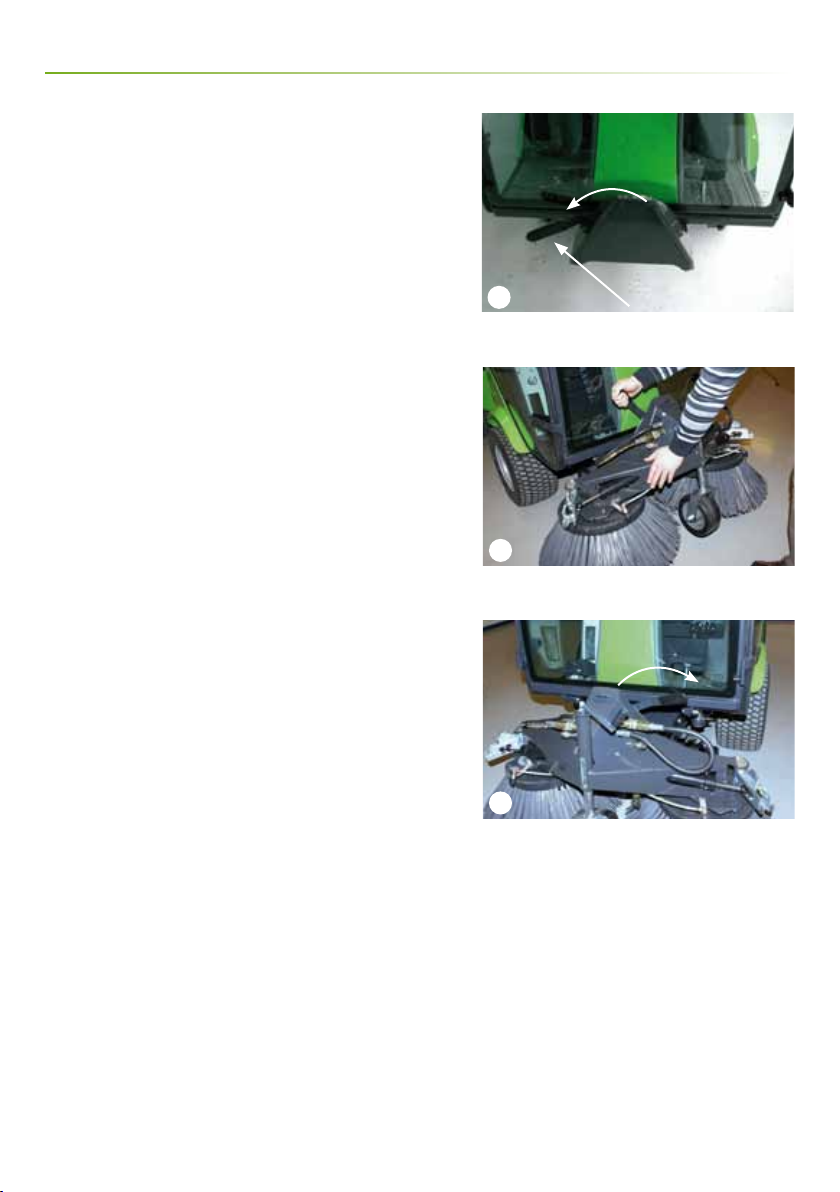
2.2 Assembly / Disassembly
Fitting the front brush
1. The locking handle on the A-frame of the basic machine
must be in the unlocked position. (Picture 1)
2. Drive the base machine right up to the A-frame of the
brushes, so the A-frames t into each other.
3. Raise the A-frame by pulling the joystick back until the
brushes are free of the ground.
4. Stop the machine
5. Tilt the attachment into the machine. (Picture 2)
6. Lock the attachment in place by turning the locking
handle on the A-frame all the way to the right. (Picture 3)
Removing the front brush
Follow the tting procedure in reverse order.
Locking handle
Tilt the attachment into the machine
Locking
Operator’s Manual City Ranger 2200 Suction Sweeper
L
o
c
k
e
d
U
n
l
o
c
k
e
d

1
2
3
4
9
Fitting side-brushes
One or two side-brushes can be tted onto the unit. The
side-brushes are identical, and can be tted on either side
of the unit, though the water-sprayers must be adjusted
when a side-brush is moved over to the opposite side of
the unit.
1. Lower front brushes.
2. Stop the machine.
3. Detach the hydraulic hose. (Picture 1)
4. Lift the side-brush under the panel for the hydraulic
motor. (Picture 2)
5. Guide the side-brush to the front-brush xture. (Picture 3)
6. Snap on the side-brush. (Picture 4)
(Continues on page 10)
Operator’s manual
Operator’s Manual City Ranger 2200 Suction Sweeper
Side-brush
Front-brush xture
Snap on the side-brush
Detach the hydraulic hose

1
2
10
Operator’s Manual
7. Fit the hydraulic hoses and the water hoses. (Pictures 1
and 2)
8. Adjust the water-sprayers.
9. Tighten the bolts on the side-brushes regularly.
Removing side-brushes
Follow the assembly procedure in reverse order.
Hydraulic hoses + water hoses on the A-frame are tted
Hydraulic hoses + water hoses on the side-brush are tted
Operator’s Manual City Ranger 2200 Suction Sweeper

1
2
3
4
11
Operator’s Manual
Fitting the hopper
1. Reverse the machine up to the hopper, which is placed
on the hopper frame.
2. Stop the machine.
3. Check the locking handle is in the open position. The
hooks must be in the position shown in the picture.
(Picture 1)
4. Check that the hydraulic couplings are clean and not
dirty. If necessary, wipe with a dry cloth. (Picture 2)
5. Push the hopper in over the loading panel until there is
approx. a 5 cm gap between the hopper frame and the
back bumper. (Picture 3) The hopper must be centrally
placed over the machine.
6. Press the lever down, push the locking latch free from
the barb and lower the hopper slowly over the machine.
(Picture 4)
Locking lever – unlocked
Cleaning couplings
Fitting the hopper
Locking lever
Operator’s Manual City Ranger 2200 Suction Sweeper
1
2
12
7. Check the hopper is correctly attached to the machine.
8. Free the hopper frame from the hopper.
9. Press the grip on the locking handle in and turn it anti-
clockwise. Pull the lever out and move it up. (Picture 1)
10. Fix the hopper securely to the machine by turning the
lever 1/3 clockwise. (Picture 2)
11. Push the lever in, opposite way to point 9.
Attention!
Keep ngers and hands away as there is
a danger of crushing. Keep a good grip of
the hopper frame lever when the hopper
is lowered.
Removing the hopper
Follow the tting procedure in reverse order.
Operator’s Manual
The locking handle is pulled out
The locking handle is turned
Operator’s Manual City Ranger 2200 Suction Sweeper

1
2
3
4
13
2.3 Checks before start-up
1. Topping-up the water
It is important the water tank is lled up before starting.
(Picture 1)
The water level can be read on the right side of the hopper.
(Picture 2)
A water-sprayer is positioned in the hopper (Picture 3)
and a water-sprayer is positioned in front of each brush.
(Picture 4)
Two water-sprayers have enough water for approx. 1 ¾
hours of use. Four water-sprayers have enough water for
1 ¼ hours of use. If only the water-sprayer in the hopper is
used, then it will have enough water for four hours of use.
Topping-up the water
Tank gauge
Water-sprayer in the hopper
Water-sprayer – front brush
Operator’s Manual City Ranger 2200 Suction Sweeper
Operator’s Manual
3
2
1
4
4
14
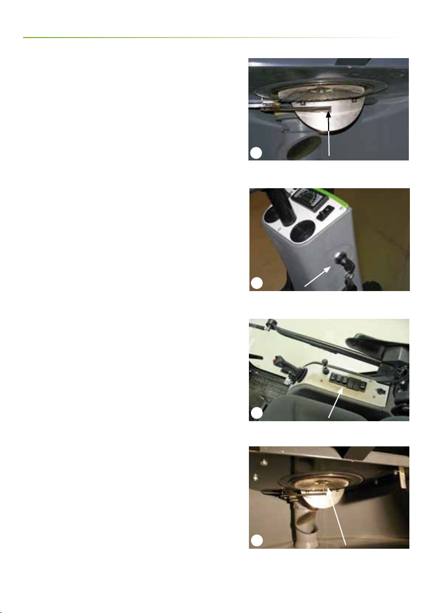
2. Checking the rotary lter and turbine
Checking the rotary lter and turbine. (Picture 1)
Remove any dirt before starting. (See Section 3.1)
3. Checking the rotary lter water-sprayer.
1. Engage the handbrake.
2. Turn the ignition key to position 1 WITHOUT starting the
machine. (Picture 2)
3. Switch the rear PTO ON. (Picture 3)
4. Check water comes out of the water-sprayer below the
lter in the hopper tank. (Picture 4)
4. Adjusting brushes
Correctly adjusted brushes last longer. Make sure the
brushes do not press too hard against the surface being
cleaned.
(See Section 2.8)
Attention!
The Suction Sweeper must not be used if the water-
sprayer in the hopper is not working.
Stop the turbine immediately if there is imbalance/
vibration in the lter or in the turbine.
A low-level switch has been tted which automatically
stops the water pump if the water tank is empty.
Operator’s Manual
Ignition key – position 1
PTO (rear)
Water-sprayer in the hopper
Checking the rotary lter and turbine
Operator’s Manual City Ranger 2200 Suction Sweeper

15
2
3
1
Operator’s Manual
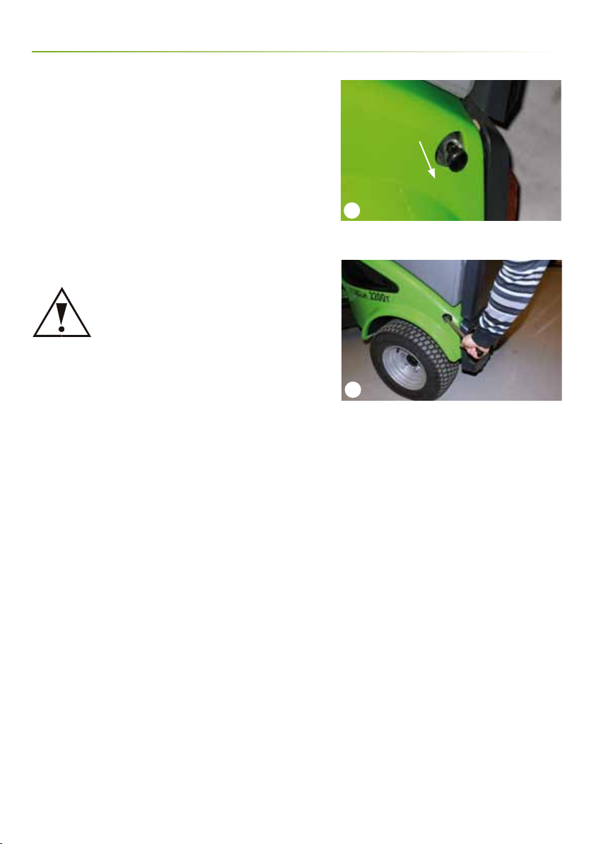
Avoid roll-overs
Check tyre pressure
The tyre pressure must be checked and adjusted to 1.5 bar
(22 psi) when the Suction Sweeper is attached.
Do not drive the machine in a place where it can slide, tip
or roll. Do not drive on slopes with an incline of more than
10°. (Picture 1)
Transport lock
The transport lock prevents the attachment from lowering
during transport.
How to use the transport lock: Move the handle to the
uppermost position. Lift the A-frame by moving the
joystick up. As the A-frame lifts, the transport lock is
automatically activated. (Picture 2)
How to unlock the transport lock: Unhitch the handle
and lift the A-frame to the uppermost position. The
attachment can now be lowered again. (Picture 3)
Operator’s Manual City Ranger 2200 Suction Sweeper
Transport lock – locked
Transport lock – unlocked
Max. 10°
Do not drive on slopes with an incline of more than 10°
2
1
16
Operator’s Manual
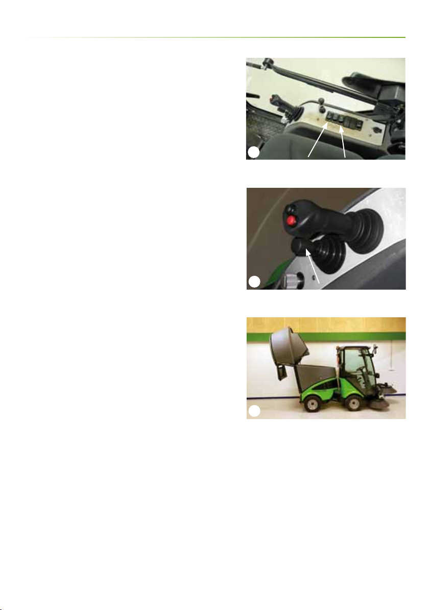
2.4 Suction Sweeper start-up
1. Start the machine
2. Switch ON the rear PTO (suction begins). Water for the
rotary lter starts to ow when the rear PTO is switched
on. (Picture 1)
3. Switch ON the front PTO (brushes rotate). (Picture 1)
4. Move throttle to full. (Picture 1)
5. Lower the front brushes by moving the joystick down.
(Picture 2)
6. Engage the weight distribution using the red button on
the joystick. (Picture 2) The front brushes will now adjust
to ground conditions. To adjust the weight distribution:
Read
the operator’s manual for the basic City Ranger 2200
machine.
7. If the two front water-sprayers are to be used, then switch
them on using the “Water front brushes” switch. (Picture 1)
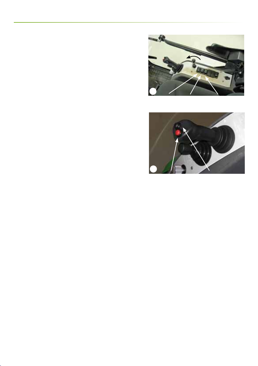
2.5 Using side-brushes (optional
equipment)
The joystick controls the side-brushes’ movements.
A side-brush is automatically lowered as it moves out from
the machine.
Using right side-brush
The side-brush follows the joystick’s sideways movement.
Moving the joystick to the right moves the side-brush out.
Moving the joystick to the left moves the side-brush back in.
Using left side-brush
To switch over to the left side-brush, push the black
button on the joystick (Picture 2) and move the joystick
at the same time. The side-brush follows the joystick’s
sideways movement. Moving the joystick to the left moves
the side-brush out. Moving the joystick to the right moves
the side-brush back in.
Weight distribution Engaging the left side-brush
PTO front Water front brushes PTO rear
Operator’s Manual City Ranger 2200 Suction Sweeper

1
2
3
4
17
Operator’s Manual
Manual start button
Change-over handle
Locking clip is released by lifting
Handle – vacuum nozzle
2.6 Using external vacuum hose
Ready for use
1. Engage the handbrake.
2. Switch the rear hydraulics ON while holding the manual
start button down. (Picture 1)
3. Push the throttle to maximum.
4. Turn the change-over handle so the arrow points down.
(Picture 2)
5. Lift the locking clip and pull the vacuum hose out.
(Picture 3)
6. Pull out the vacuum nozzle. (Picture 4)
Operator’s Manual City Ranger 2200 Suction Sweeper

1
2
18
Storing the external vacuum hose
1. Place the vacuum nozzle in the holder. The hose rolls up
together. (Picture 1)
2. Fold the handle in.
3. Snap the handle into the lock.
4. Turn the change-over handle so the arrow points up.
(Picture 2)
Operator’s Manual
Locked Vacuum nozzle Handle
Change-over handle
Operator’s Manual City Ranger 2200 Suction Sweeper
1
2
3
19
Operator’s Manual
2.7 Emptying the hopper
The hopper can empty directly onto the ground or tip into
a container.
Tipping height 130 cm.
Attention!
Before emptying the hopper, make sure that:
A) The machine is on a level surface, and that it is not
“angled”.
B) That there is sucient space for the opened back cover.
1. STOP the front and rear PTO. (Picture 1)
2. Drive to the nearest disposal area.
3. Begin emptying by using the lower joystick to tip the
hopper. (Picture 2)
4. Lower the joystick once the hopper is empty (the hopper
will move back to its normal position). Release the handle
when the hopper is back in position. The hopper is tted
with a hose-break valve, which will close if the hopper
lowers too quickly. If this happens, raise the hopper a little
again and then lower it slowly. (Picture 3)
Attention!
The rear hatch must not be opened until suction has
ceased. Otherwise there is a risk of personal injury. The
suction continues to run for approx. 15 s after the turbine
has been switched o (PTO rear).
There is a risk of crushing while the hopper is being
emptied.
Make sure the hopper is completely lowered after
emptying!
PTO front PTO rear
Bottom joystick
Hopper tips all the way back
Operator’s Manual City Ranger 2200 Suction Sweeper

1
20
Operator’s Manual
Operator’s Manual City Ranger 2200 Suction Sweeper
2.8 Emptying the hopper for water
The water in the hopper can be emptied by unscrewing
the drain plug. (Picture 1)
2.9 Protect the Suction Sweeper against ice
during the winter
1. Pouring a solution of water and anti-freeze into the
water tank – the same solution as if protecting a sprinkler
system against ice.
2. Turning the turbine and water supply to the front
brushes on, the liquid runs through the whole system and
protects it against ice.
Drain plug
Other manuals for City Ranger 2200
2
Table of contents
Other Nilfisk Egholm Blower manuals

Popular Blower manuals by other brands


Sanitaire
Sanitaire SC6056 owner's guide

Craftsman
Craftsman 358.794733 Operator's manual

Jonsered
Jonsered BV 2125C instruction manual

Weed Eater
Weed Eater 530163804 instruction manual

Legend Brands
Legend Brands Sahara Pro TurboDryer X4 owner's manual

American-Lincoln
American-Lincoln 114RS Operator's manual & parts list