NIMO ACTV007 User manual


PAG 1
La antena UHF envía y recibe
señales del mando a distancia.
Directional 5.8GHz antenna
sends and receives audio and
video signals
La antena direccional de 5,8GHz envía y
recibe señales de audio y video.
UHF antenna sends and receives remote
control signal
Las luces indicadoras de canal deben estar
posicionadas en el mismo número tanto en
emisor como en receptor.
Channel indicator lights must be set to
same number on both transmitter and
receiver (4 CH or 2 CH).
Utilice el botón de selección de
canal para encontrar la recepción
óptima, seleccione el mismo canal
tanto en emisor como en receptor.
Channel selection button use to
nd optimum reception, most
select same channel on both
transmitter and receiver.
Salida de extensor
de infrarrojos.
IR extender output
port.
Entrada izq. de audio
(blanco).
Entrada izq. de audio
(rojo).
Entrada izq. de video
(amarillo).
Audio L in (white)
Audio R in (red)
Video in (yellow)
Entrada de corriente
DC, conéctela
al adaptador de
corriente de 9V.
DC power input,
connect to power
adapter (9VDC)
VISTA FRONTAL DEL EMISOR Y RECEPTOR
FRONT VIEW FOR TRANSMITTER AND RECEIVER
Los infrarrojos del control remoto pasan a
través de esta ventana para controlar de
audio y video.
Remote control window infrared passes
through this to remotely control audio/video
source.
Entrada de corriente
DV, conéctela
al adaptador de
corriente de 9V.
DC power input,
connect to power
adapter (9VDC)
Entrada izq. de audio
(blanco).
Entrada izq. de audio
(rojo).
Entrada izq. de video
(amarillo).
Audio L in (white)
Audio R in (red)
Video in (yellow)

PAG 2
TRANSMITIR AUDIO/VIDEO DESDE SU REPRODUCTOR DE VIDEO.
HOW TO TRANSMIT AUDIO/VIDEO FROM YOUR VCR
INSTALACIÓN DEL TRANSMISOR INALÁMBRICO AV DE 5,8GHZ.
SETTING UP 5.8GHZ WIRELESS AV LINK

PAG 3
CONEXIÓN DEL RECEPTOR DIRECTAMENTE A LA TV.
CONNECTING RECEIVER DIRECTLY TO REMOTE TV.
TRANSMITIR AUDIO / VIDEO DESDE SU RECEPTOR SATELITE.
HOW TO TRANSMIT AUDIO/VIDEO FROM YOUR SATELLITE RECEIVER

PAG 4
ORIENTANDO LAS UNIDADES PARA UN RENDIMIENTO ÓPTIMO.
ORIENTING UNITS FOR OPTIMUM PERFORMANCE.
CONEXIÓN DEL RECEPTOR A LA TV A TRAVÉS DEL VIDEO.
CONNECTING RECEIVER TO REMOTE TV THROUGH VCR.
Antena control
remoto
Remote control
antenna
Antena parte alta
Antenna top site
EMISOR / TRANSMITTER RECEPTOR / RECEIVER
Antena control
remoto
Remote control
antenna
Antena parte alta
Antenna top site

PAG 5
ORIENTACIÓN DE LAS ANTENAS DE AV.
ORIENTING THE AUDIO/VIDEO ANTENNAS.
EMISOR / TRANSMITTER
RECEPTOR / RECEIVER
UTILIZAR EL EXTENSOR DE INFRARROJOS.
HOW TO USE THE IR EXTENDER ACCESSORY.
DVD / VIDEO / SATELITE
RECEPTOR DE INFRARROJOS
INFRARED RECEIVER
RECEPTOR / RECEIVER
EMISOR / TRANSMITTER

PAG 6
CONTENIDO DE LA CAJA.
Compruebe que están los siguientes componentes en la caja.
Transmisor, receptor, adaptador de corriente x2, cable RCA a RCA x2, extensor de infrarrojos y manual de usuario.
INTRODUCCIÓN AL TRANSMISOR INALÁMBRICO DE AV DE 5,8GHZ.
Este sistema de transmisión consta de un transmisor inalámbrico de audio/video que utiliza tecnología de comunicación
inalámbrica para proporcionar una transmisión nítida y constante en un radio de hasta 100m (en óptimas condiciones).
Este equipo trabaja en alta frecuencia 5,8GHz., evitando frecuencias bajas que utilizan teléfonos inalámbricos y otros
transmisores. Para minimizar las interferencias se utilizan antenas direccionales de alta ganancia y polarizadas circularmente.
También integra un extensor del mando a distancia UHF que el permitirá controlar la fuente de audio o video desde otra
habitación.
APLICACIONES DOMÉSTICAS.
Ver el DVD, video, ... en cualquier habitación de la casa.
Ver programas de TV o satélite en cualquier habitación de la casa.
Escuchar música en calidad estéreo desde el receptor, en altavoces que se encuentren en el radio de acción del equipo.
Mostrar imágenes del ordenador en cualquier TV (se necesitan equipos adicionales).
El funcionamiento de este dispositivo está sujeto a las siguientes condiciones:
- Este dispositivo no debe causar interferencias perjudiciales.
- Este dispositivo debe aceptar cualquier interferencia recibida incluyendo interferencias que puedan
causar un funcionamiento no deseado.
- Para evitar riesgo de incendio o descargas eléctricas, no exponga este aparato a la lluvia o humedad.
- No abra este aparato.
- Este a aparato sólo debe utilizarse con el cable de corriente incluido.
ADVERTENCIA. Los cambios o modicaciones aprobados expresamente por la parte responsable de su cumpli-
miento podrían anular la autoridad del usuario para utilizar este equipo.
NOTA. Este equipo ha sido probado con exhaustividad y cumple con las Normas FCC, que establecen una protec-
ción razonable contra interferencias dañinas en instalaciones de uso doméstico. Este equipo genera, usa y puede
emitir energía de radio frecuencia si no se instala y utiliza según las instrucciones, pueden causar interferencias
perjudiciales para las comunicaciones de radio. Sin embargo, no hay ninguna garantía de que no se produzcan
interferencias en una instalación doméstica.
Si este equipo causa interferencias en recepciones de radio o TV (comprobar encendiendo y apagando el equipo),
se recomienda al usuario que intente corregir las interferencias por medio de las siguientes medidas:
Reoriente o coloque en otro lugar la antena receptora.
Aumente la distancia entre el equipo y el receptor.
Conecte el equipo a un enchufe con un equipo diferente al que está conectado el equipo.
Consulte a su distribuidor o a un técnico de radio/TV cualicado.

PAG 7
APLICACIONES DE SEGURIDAD.
Sistema de seguridad inalámbrico.
Vigile a través del TV a los niños en otras habitaciones con ayuda de su video cámara.
Puede ver desde el interior a cualquier persona al otro lado de la puerta antes de abrir (mediante una mini cámara CCD).
Grabar reuniones desde otra habitación.
NORMAS DE UTILIZACIÓN.
El aparato y el enchufe de red deben tener el mismo voltaje.
Asegúrese de que el transmisor y el receptor están conectados correctamente al equipo.
Si el transmisor y el receptor se apagan, espere unos segundos antes de reiniciar.
Ajuste el plato de la antena para reducir interferencias.
Cuando utilice dos o más equipos a la vez, seleccione varios canales.
Un transmisor puede utilizar varios receptores.
No utilice microondas cerca de este equipo.
El mando a distancia debe apuntar hacia el extensor de infrarrojos del receptor.
El extensor de infrarrojos del transmisor debe orientarse hacia la ventana receptora de infrarrojos del equipo de la fuente A/V.
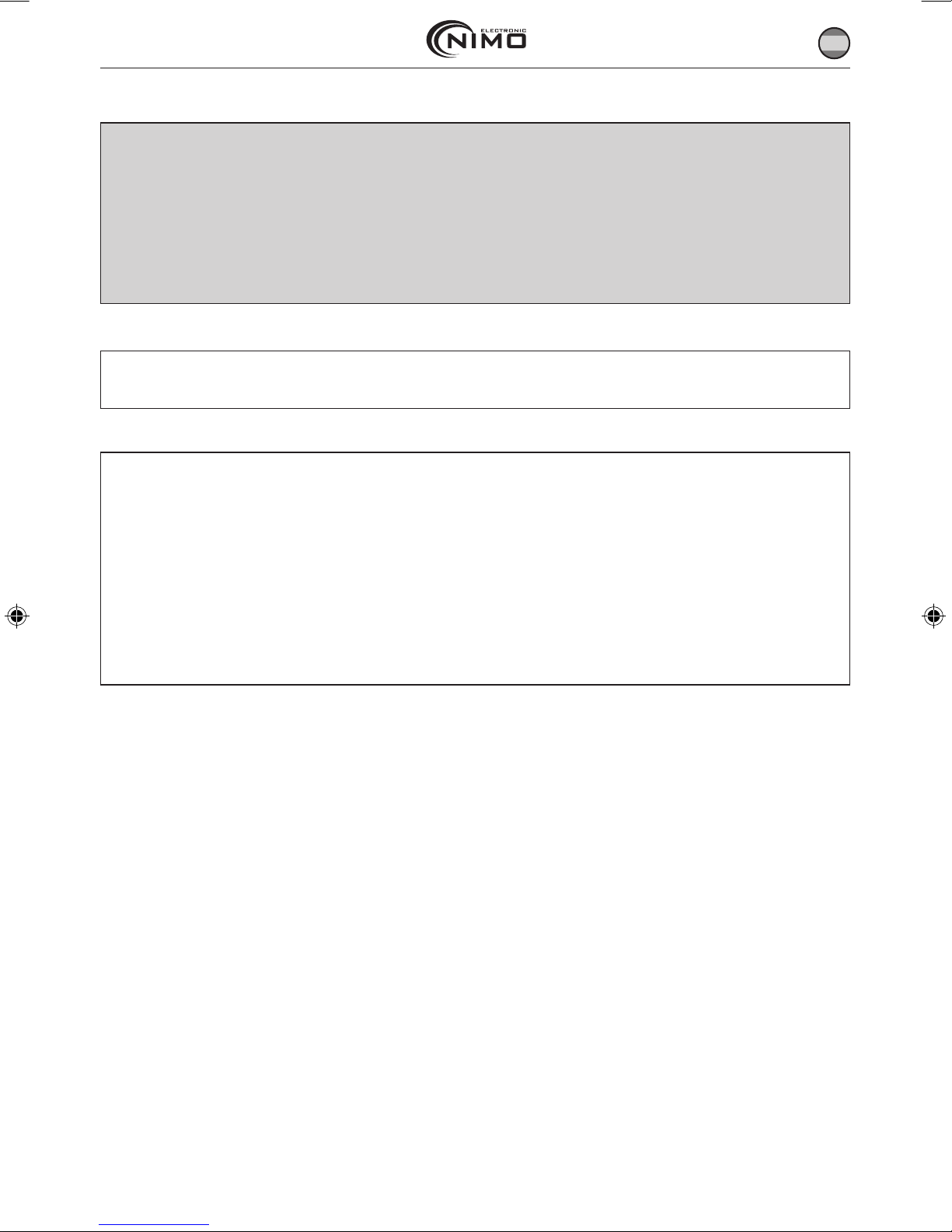
INSTALACIÓN DEL TRANSMISOR INALÁMBRICO AV DE 5,8GHZ. (PAG 2).
Para disfrutar de audio y video desde otra habitación, conecte el transmisor a la fuente de audio/video que desee repro-
ducir en la sala 1 y conecte el receptor al televisor, monitor o altavoces en la sala 2.
Se recomienda conectar el sistema de transmisión de AV a los siguientes equipos.
VIDEO. VCR, DVD, TDT, satélite y cámara de video.
AUDIO. Cargador de CD, discman y receptores estéreo.
NOTA: Asegúrese de que el interruptor ON/OFF está en posición OFF antes de hacer la conexión.
TRANSMITIR AUDIO/VIDEO DESDE SU REPRODUCTOR DE VIDEO. (PAG 2).
1. Conecte un cable de audio/video (RCA o euroconector) al conector de AV del emisor y a los conectores de salida AV de
la parte trasera de su reproductor de video.
2. Conecte un extremo del adaptador de corriente en la parte trasera del transmisor y el otro extremo en un enchufe de
230V. Utilice únicamente el adaptador suministrado con el aparto.
3. Si su reproductor de video tiene una única salida de AV y quiere utilizarlo junto a un TV, conecte el cable coaxial de
75 Ohm de la salida de su video a la entrada de cable coaxial de su TV.
4. Localice y oriente el emisor como se indica en el sección de este manual titulada “ORIENTANDO LAS UNIDADES PARA
UN RENDIMIENTO OPTIMO” para conseguir la mejor calidad de la señal.
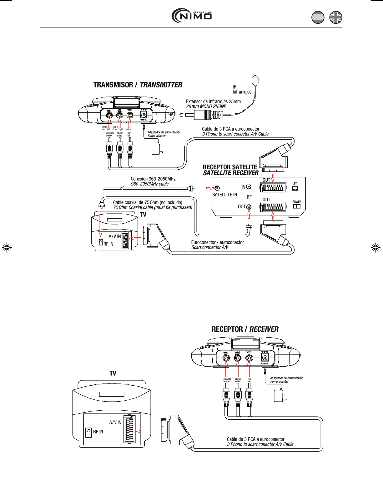
TRANSMITIR AUDIO / VIDEO DESDE SU RECEPTOR SATELITE. (PAG 3).
Para transmitir audio/video directamente desde su receptor satélite o bien conectándolo a su video siga las instrucciones.
1. Conecte un cable de AV a los conectores AV del transmisor y a los conectores de salida de AV.
2. Enchufe a la red el adaptador de corriente.
3. Si su receptor satélite o reproductor láser disc tiene únicamente una salida AV, conecte el cable coaxial desde la salida
del receptor satélite a la entrada coaxial del televisor.
4. Localice y oriente el emisor como se indica en el sección de este manual titulada “ORIENTANDO LAS UNIDADES PARA
UN RENDIMIENTO OPTIMO” para conseguir la mejor calidad de la señal.

PAG 8
RECIBIR SEÑALES INALÁMBRICAS DE AV EN LA TV.
Existen dos maneras de recibir señales inalámbricas de AV en la TV remota.
1. Conectando el receptor directamente a la TV remota.
2. Conectando el receptor a un video que está conectado a la TV.
NOTA. Si su TV tiene capacidades multi imagen podrá ver cualquier imagen transmitida por el emisor, como su bebé
durmiendo en un pequeño cuadro, mientras disfruta de otro programa en el resto de la pantalla. Consulte el manual de
su TV para saber cómo utilizar estas capacidades.
CONEXION DEL RECEPTOR DIRECTAMENTE A LA TV. (PAG 3).
Si su TV tiene conectores AV conecte un cable AV a los conectores de Av de la TV y a los conectores de salida AV del
receptor. Si la TV tiene un conector de entrada para audio, conecte el cable blanco de audio en ese conector.
CONEXIÓN DEL RECEPTOR A LA TV A TRAVÉS DEL VIDEO. (PAG 4).
Esta instalación le permite grabar el audio/video transmitidos en su video remoto y además disfrutar la imagen y el
sonido en la televisión al mismo tiempo.
1. Conecte los cables AV del receptor a los conectores AV del video.
2. Si su TV no tiene entrada AV, conecte un cable coaxial de 75 Ohm desde la entrada de antena de la TV a la salida de
antena del video.
OPCIONAL
3. Enchufe un extremo del adaptador de corriente en la parte trasera del receptor y el otro extremo en algún enchufe de
red. Utilice únicamente el adaptador suministrado.
4. Localice y oriente el emisor como se indica en el sección de este manual titulada “ORIENTANDO LAS UNIDADES PARA
UN RENDIMIENTO OPTIMO” para conseguir la mejor calidad de la señal.
ORIENTANDO LAS UNIDADES PARA UN RENDIMIENTO ÓPTIMO. (PAG 4).
Este sistema de envío debe colocarse en una supercie plana y estable para prevenir daños evitando caídas.
Para un rendimiento óptimo, las antenas de AV deben estar orientadas correctamente. Para un rango de operación máxi-
mo, intente minimizar el número de obstáculos (electrodomésticos, muebles grandes, ...) entre el emisor y el receptor.
ORIENTACIÓN DE LAS ANTENAS DE AV. (PAG 5).
El emisor envía su video y audio de alta calidad por medio de antenas direccionales que deben estar orientadas de cierta
forma para obtener resultados óptimos. Podrá girar las antenas para la orientación correcta.
En la mayoría de los casos, la cara plana de las antenas, tanto en el emisor como en el receptor, debe estar apuntando
a la otra de forma perpendicular (en el ángulo correcto) a una línea imaginaria entre ambas unidades. Se muestran tres
ejemplos en las siguientes guras. Como todas las casas son diferentes, para una recepción óptima, puede que sean
necesarios diferentes giros. Se sugiere dejar las antenas planas si la distancia es igual o menor de 2 metros.
UTILIZACIÓN DEL MANDO A DISTANCIA.
Este sistema de envío no permite únicamente mandar el AV de un lugar a otro, sino que también le da la oportunidad de
controlar la fuente de AV utilizando su mando a distancia. Convierte la señal infrarroja emitida por su mando a distancia
a una señal UHF en el receptor y la envía al emisor donde la señal de UHF es convertida de nuevo a la señal original de
infrarrojos y enviada a la fuente de AV.

PAG 9
UTILIZACIÓN DEL MANDO A DISTANCIA.
Hay dos formas de controlar la fuente AV utilizando el mando a distancia.
1. Orientar el emisor directamente hacia el equipo AV, permitirá que la señal convertida de infrarrojos vaya directamente
de la ventana de infrarrojos del emisor al panel frontal del equipo fuente de AV.
2. Simplemente conecte el extensor de infrarrojos al emisor y coloque este extensor cerca de la fuente de AV.
En ocasiones puede ser difícil o incluso imposible orientar el emisor de forma que está enfocada directamente al equipo
que desea controlar, en este caso, el uso del extensor es el más adecuado.
UTILIZAR EL EXTENSOR DE INFRARROJOS. (PAG 5).
El extensor de infrarrojos se conecta al emisor a través de su conector especíco. El extensor emite una señal infrarroja
que permite controlar su equipo AV mediante la señal remota. Para utilizar el extensor de infrarrojos siga las instruccio-
nes que se detallan a continuación.
1. Conecte el extensor de infrarrojos en el conector de 2,5mm de la parte trasera del emisor.
2. Conecte el cable de infrarrojos en la parte izquierda del emisor y apunte a uno de los LED del receptor de infrarrojos
de la fuente AC. Tiene 3 LED más a su disposición para controlar 3 aparatos AV más.
Mueva el LED para encontrar el punto más adecuado.
3. Coloque el receptor de forma que la señal del control, remoto apunte a la ventana de infrarrojos de la parte inferior-
frontal de la unidad. Para utilizar su control remoto, apunte con él a la parte frontal del receptor.
RESOLUCIÓN DE PROBLEMAS Y MANTENIMIENTO.
PROBLEMA SOLUCIONES POSIBLES
No hay imagen o sonido - Compruebe la conexión de los cables.
- Asegúrese de que los cables de corriente de la TV remota y de la fuente de video (video,
TDT, ...) esté conectada.
- Compruebe los interruptores ON/OFF del emisor y receptor.
Interferencias - Ajuste la orientación de la antena de receptor y emisor como se indica en la sección de
este manual titulada “ORIENTANDO LAS UNIDADES PARA UN RENDIMIENTO OPTIMO” para
conseguir mejor calidad de la señal.
- Seleccione un canal diferente pulsando el botón selector de canal tanto en el emisor
como en el receptor de forma que ambos coincidan.
- Si utiliza un microondas, apágelo.
- No permita que le horno microondas estén entre emisor y el receptor.
El extensor del mando a
distancia no funciona
- Compruebe que no hay obstáculos entre el emisor y la fuente de AV.
- Compruebe si la ventana de IR en la parte inferior-frontal del emisor está bloqueada.
- Asegúrese de que el extensor de infrarrojos está correctamente girado en el equipo AV
que quiere controlar como se indica en la sección “UTILIZACIÓN DEL MANDO A DISTAN-
CIA” en este manual.
- Apague la unidad y reiníciela.

PAG 10
ESPECIFICACIONES
EMISOR.
Banda de frecuencia 5.75GHz~5.81GHz.
Potencia de emisión 20mW Max..
Modulación FM (video and audio).
Canal PLL frequency synthesizer.
Nivel de entrada video 1V p-p 75 Ohm.
Nivel de entrada video 1V p-p 600 Ohm (estéreo).
Puerto de entrada A/V jack-RCA line jack.
Antena Directional at antenna.
IR remoto salida IR 940nm with ON/OFF keying.
Adaptador de corriente 9VDC, 400mA .
Dimensiones 140mm×113mm×42mm.
Peso 200g.
RECEPTOR.
Banda de frecuencia 5.75GHz~5.81GHz
Sensibilidad -80dBm Min.
Canal PLL frequency synthesizer
Nivel de salida de video 1V p-p 75 Ohm.
Nivel de salida de video 1V p-p 600 Ohm (estéreo).
Puerto de salida A/V jack-RCA line jack.
Antena Directional at antenna.
IR REMOTO.
Frecuencia de transmisión 433.92 MHz.
Entrada de frecuencia IR 35KHz~41 KHz.
Adaptador de frecuencia 9 VDC, 400mA.
Dimensiones 140mm×113mm×42mm.
Peso 220 g.
SISTEMA.
Alcance operativo hasta 100 metros (en óptimas condiciones).
Alcance del mando a distancia hasta 50 metros (en óptimas condiciones).
Estas especicaciones están sujetas a cambios.

PAG 11
CHECKING CONTENTS OF BOX
Checks to make sure that all of the items shown as below are included with your 5.8 GHz Wireless Video Sender System.
Transmitter, receiver, adaptador de corriente x2, cable RCA a RCA x2, extensor de infrarrojos y manual de usuario.
INTRODUCTION TO 5.8GHZ WIRELESS AV LINK
This sender system is a wireless audio/video sender that uses advanced wireless communication technology to deliver
consistently sharp audio and video up to 100 meters away. By transmitting at a very high frequency (5.8 GHz), it avoids
the crowded 900 MHz and 2.4 GHz band used by many cordless telephones and other wireless audio/video transmitters.
It’s superior quality is due to wide-band FM rather than AM signal modulation. Circular polarized high-gain directional
transmitting and receiving antennas are used to minimize interference from unwanted signals and maximize the signal
range.
It also integrates an UHF remote control extender to allow you to control the audio or video source from another room
using your existing remote controller.
Using sender system, you can enjoy greater convenience and security in many ways:
IMPORTANT-SAFETY PRECAUTIONS
This device of which operation is subject to the following two conditions
- This device may not cause harmful interference, and no useful part is inside. Do not open it.
- This device must accept any interference received, including interference that may cause undesired operation.
- To prevent re or shock hazard, do not expose this device to rain or moisture.
- Do not use near a bathtub, washbowl, kitchen sink, or laundry tub, in a wet basement, or near a swimming pool.
- To avoid electrical shock, do not open this device.
- This device should be operated to use only the power supply included with it or provided as an accessory.
- Do not overload wall outlets and extension cords as this can result in the risk of re or electrical shock.
- Do not attempt to service this device yourself. Refer servicing to qualied personnel only.
CAUTION. Changes or modications not expressly approved by the Party responsible for compliance could void the
user’s authority to operate the equipment.
NOTE.This equipment has been tested and found to comply with the limits for a class B digital device, pursuant
to Part 15 of the FCC Rules, R&TTE directive. These limits are designed to provide reasonable protection against
harmful interference in a residential installation. This equipment generates, uses and can radiate radio frequency
energy, if not installed and used in accordance with the instruction, it may cause harmful interference to radio
communications. However, there is no guarantee that interference will not occur in a particular installation. If this
equipment does cause harmful interference to radio or television reception, which can be determined by turning
the equipment off and on, the user is encouraged to try to correct the interference by one or more of the following
measures:
Reorient or relocate the receiving antenna.
Increase the separation between the equipment and receiver.
Connect the equipment into an outlet on a circuit different from that to which the receiver is connected.
Consult the dealer or an experienced radio/TV technician for help.

PAG 12
GENERAL APPLICATION
Watch the movie you rent on any TV in house without moving your VCR, laser disc player or running messy cables.
Watch cable or satellite programs on any TV in house.
Listen to stereo-quality music from your receiver on any powered speakers
inside or outside the house.
Uses multi-receivers for broadcasting to numerous TV sets in other rooms.
Show computer images on a remote TV. (Additional equipment required)
SAFETY & SECURITY APPLICATION:
Applies as a wireless security system.
Monitor your sleeping baby, playing children, the elderly, or the disabled on TV using your existing camcorder.
See who is outside the door on TV through your camera or miniature CCD camera.
Monitors and records meeting from another room.
And many more uses!
THE USING ATTENTION.
The outlet of the power supply must have the same voltage as the local area.
Be sure the transmitter and the receiver were connected to the equipment correctly (e.g. Connect the transmitter to the
VCR, and the receiver to the TV).
When switch is off from transmitter or receiver, it needs to wait for a few seconds in order to restart again.
Adjust antenna plate for least interference. (Adjustment cannot rotate more than ±180°)
In most situations, one set of equipment has a better feature within 100 meter. When two equipment or more is used at
the same time, used different channels. But a transmitter can be used with several receivers at the same time.
The channel selectors allow you to choose the channel for best feature and least interference.
When the equipment is operating, please do not use a microwave oven near by.
The remote control should face to the receiver IR remote control window, and the transmitter IR remote control window
(or IR extender) should face to the source A/V equipment. The IR remote has to be within the standard distance.
PANEL CONTROLS AND FEATURES OF DUPLEX FUNCTION TYPE.
The following illustrations show the names of each component, button and switch connectors on the transmitter and
receiver.
SETTING UP 5.8GHZ WIRELESS AV LINK. (PAG 2).
To enjoy wireless video and audio, just connect the transmitter to whatever audio/video source you want to enjoy from
another location, and connect the receiver to the TV, monitor or powered speakers in that other location.
A/V link system is suggested to connect to following A/V equipment use.
Make sure the ON/OFF switch is in the OFF position before connection
Video sources. VCR, Cable set-top box (with A/V output), Satellite Receiver, Laser Disc Player, Camcorder or Miniature
CCD Camera, Digital decoder, DVD
Audio sources. Compact Disk player or Changer, Stereo Receiver, Cassette Deck.
HOW TO TRANSMIT AUDIO/VIDEO FROM YOUR VCR. (PAG 2).
1. Connect one set of audio/video (A/V) cables (RCA or SCART cable) to the A/V jack of the transmitter and to the A/V
output jacks (RCA or connector) on the back of your VCR.
2. Plug one end of the power adapter into the back of the transmitter and the other end into any 230-volt wall outlet (or
120-volt). Use only the adapter provided.

PAG 13
3. If your VCR has only one set of A/V output jacks and you want to use it with a nearby TV, connect 75ohm RF coaxial
cable from the modulator signal OUT port on your VCR to the RF IN port on your TV.
Note: In order to also view cable programs on that TV, connect your incoming cable TV source to the IN port of the VCR.)
4. Locate and orient the transmitter according to the section of this manual titled “Orienting Units for Optimum Perfor-
mance” for best performance of transmitter.
HOW TO TRANSMIT AUDIO/VIDEO FROM YOUR SATELLITE RECEIVER. (PAG 3).
You can transmit audio/video either directly from your satellite receiver, or by connecting them to your VCR. To transmit
directly from your satellite receiver, follow the instructions below.
1. Connect one set of audio/video (A/V) cables (RCA or SCART cable) to the A/V jacks of the transmitter and to the audio/
video OUT jacks (RCA or SCART connector) of the satellite receiver or laser disc player.
2. Plug one end of the power adapter into the back of the transmitter and the other end into any 230-volt wall outlet (or
120-volt). Use only the adapter provided.
3. If your satellite receiver or laser disc player has only one set of A/V output (RCA or SCART connector) jacks, in this
case, please connect 75ohm RF coaxial cable from satellite receiver’s modulator output port to TV RF input terminal.
4. Locate and orient the transmitter according to the section of this manual titled “Orienting Units for Optimum Perfor-
mance” for best performance of transmitter.
HOW TO RECEIVE WIRELESS AUDIO/VIDEO SIGNALS ON YOUR TV.
There are two ways to receiver wireless audio/video signals on your remote TV (TV in another location such as in bedro-
om, kitchen).
1. Connect the receiver directly to the remote TV.
2. Connect the receiver to a VCR, which is then connected to the TV.
If your TV has picture-in-picture capabilities, you can view any image transmitted by sender, such as your sleeping baby,
in a small inset picture while enjoying other programming on the rest of the screen. Consult the owner’s manual of your
TV for instructions on using these capabilities.
CONNECTING RECEIVER DIRECTLY TO REMOTE TV. (PAG 3).
If your TV has A/V jacks, connect one set of A/V cables (RCA or SCART cable) to the TV’s A/V jacks and to the A/V output
jacks on the receiver.
If the TV has only a single jack for audio input, connect the white plug to that jack.
CONNECTING RECEIVER TO REMOTE TV THROUGH VCR. (PAG 4).
This setup enables you to record transmitted audio and video on your remote VCR and also enjoy the picture and sound
on a remote TV at the same time.
1. Connect one set of audio/video (A/V) cables to the A/V output jacks of the receiver and to the A/V input jacks on your VCR.
2. If your TV has A/V input jacks, connect another set of A/V cables to the TV’s A/V input jacks and to the A/V output jacks
on your VCR.
3. If your TV does not have any A/V input jacks, please connect a 75ohm coaxial cable from the TV’s antenna in (or RF in)
to VCR’s modulator output.
This feature is optional
4. Plug one end of the sender power adapter into the back of the receiver and the other end into any 230-volt (or 120
volt) wall outlet. Use only the adapter provided.
5. Locate and orient the receiver to best video and sound quality please according to the section of this manual titled.

PAG 14
ORIENTING UNITS FOR OPTIMUM PERFORMANCE. (PAG 4).
This sender system should be placed on a at, stable surface to prevent damage to it from falling.
For optimum performance, the audio/video antennas should be carefully oriented as described below. For maximum ope-
rating range, try to minimize the number of obstacles (e.g. your TV or other electronics, large furniture) where between
the transmitter and receiver units.
ORIENTING THE AUDIO/VIDEO ANTENNAS. (PAG 5).
Sender broadcast their high-quality audio and video using directional antennas, which must be oriented in certain con-
gurations for best results. The antennas have been designed to pivot and rotate in-almost any direction.
In most situations, the at-pitted face of the antennas on both the transmitter and receiver should be facing one another
and perpendicular (at a right angle) to an imaginary line drawn between the two units. Three examples are shown. Since
all homes are different, for optimum reception, additional slight pivots or rotations may be necessary. If the transmitter
and receiver are less than 10 feet apart, suggest keeping the antennas at in their casings since the distance is so short.
USING THE REMOTE CONTROL FEATURE.
This sender system not only allows you to send crisp audio/video from one area to another, it also gives you the ability to
control the source using your existing remote control device. It converts the infrared (IR) signal emitted by your remote
control to a radio frequency (RF) signal in UHF band at the receiver and sends it back to the transmitter where the RF
signal is converted back to the original IR signal and beamed to the audio/video source.
There are two ways to get your source A/V equipment to be controlled by using existing remote control through remote
control feature:
To orient the transmitter unit face to face the source A/V equipment, this would allow the converted IR signal, which from
transmitter IR remote control window be able to send to the source A/V equipment(s) front panel.
Simply connect an IR extender from transmitter and locate this IR extender near the source A/V equipment from panel.
Sometimes, it may be difcult or even impossible to orient the transmitter unit such that it can be “seen” (means face-
to-face) by the A/V equipment you wish to control. Perhaps there is no good surface that allows for this or perhaps you
wish to control. Or perhaps you wish to remotely control A/V equipment in different locations without re-orienting the
transmitter. So, in this case, to use in extender will be more convenient.
HOW TO USE THE IR EXTENDER ACCESSORY. (PAG 5).
The IR extender connects to the transmitter through its own special connector plug. The extender emits an IR signal can
control your A/V equipment with the remote signal.
To use the IR extender, follow the instructions below:
1. Plug the IR extender into the 2.5mm phone jack of transmitter’s rear panel.
2. Connect the infrared cable at the left of the transmitter and put one of the LED on the infrared receiver of the A/V
source. You have 3 more LED’s at you disposal to control 3 additional A/V appliances.
More the LED in order to nd the most appropriate spot.
Position the receiver so that your remote control signal can strike the IR window on the bottom front of the unit. To use
your remote control, point it at the front of the receiver.

PAG 15
TROUBLESHOOTING, CARE AND MAINTENANCE.
Please read this owner’s manual carefully and follow the steps described in it. If you still have difculties, consult the
following table. It will guide you though the most common problems and their solutions.
PROBLEM POSSIBLE SOLUTIONS
No picture or sound - Check all cable connections.
- Make sure power plugs are pushed all the way in.
- Check power switches on the remote TV and Video source. (VCR, laser disc player, satelli-
te receiver, ect. )
- Check the power on/off switches on the transmitter and receiver.
Interferencias
Noisy picture or audio
- Adjust receiver and transmitter antenna orientation. (see section on “Orienting Units for
Optimum Performance” in this manual).
- Select a different channel by pushing the channel selector button on both transmitter and
receiver so that the channels match.
- If using a microwave oven, turn it off.
- Remove microwave oven from path between transmitter and receiver.
Remote control
extender does not work
- Check the path between the transmitter and the audio/video source and clear any
obstructions.
- Check to see if the IR window on the bottom front of the transmitter is blocked.
- Make sure IR extender is properly rotated in the A/V equipment you wish to control. (see
section on “Using the Remote Control Feature” in this manual)
- Shut down the unit and restart it.

PAG 16
SPECIFICATIONS
TRANSMITTER:
Operating Frequency Band 5.75GHz~5.81GHz
Transmit Power 20mW Max.
Modulation FM (video and audio)
Channel PLL frequency synthesizer
Video Input Level 1V p-p 75 ohm
Audio Input Level 1V p-p 600 ohm (STEREO)
Input Port A/V jack-RCA line jack
Antenna Directional at antenna
IR–remote IR Output 940nm with ON/OFF keying
Power Adapter 9VDC, 400mA
Dimensions 140mm×113mm×42mm
Weight 200g
RECEIVER:
Operating Frequency Band 5.75GHz~5.81GHz
Sensitivity -80dBm Min.
Channel PLL frequency synthesizer
Video Output Level 1V p-p 75 ohm
Audio Output Level 1V p-p 600 ohm (STEREO)
Output Port A/V jack-RCA line jack
Antenna Directional at antenna
IR-REMOTE RELAY
Transmit Frequency 433.92 MHz
Infrared freq. Input 35KHz~41 KHz
Power Adapter 9 VDC, 400mA
Dimensions 140x113×42mm
Weight 220 g
SYSTEM:
Operational Range up to 100 meter (line of sight)
Remote Control Range up to 50 meter (line of sight)
All specication subject to change without notice.


Table of contents
Languages: