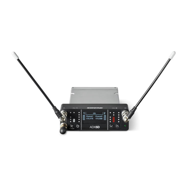
Shure ADX5D User manual

ADX5D
Portable Receiver
The Shure user guide for ADX5D.
Version: 0.1 (2020-L)
DRAFT - REVIEW ONLY

Shure Incorporated
2/33
Table of Contents
ADX5D Portable Receiver 3
IMPORTANT SAFETY INSTRUCTIONS 3
ADX5D Portable Slot-In Receiver 4
System Components 4
Hardware Callouts 5
Hardware Setup 8
Antenna Attachment 9
Rear Panel Kits 10
Attaching the Backplate 10
TA3 Standalone Backplate 10
DB15 Backplate 12
DB25 Backplate 14
IR Sync 16
Home Screen 17
Icons 17
Menus and Configuration 17
Device Configuration Menu 17
Channel Menu 21
ShowLink Remote Control 23
Setting Up a ShowLink Network 24
ADX5D ShowLink Modes 24
ShowLink Test 24
Assigning Transmitters to Transmitter Slots 25
Frequency Diversity 25
Headphone Settings 25
Firmware 26
Firmware Versioning 26
Updating the Receiver Firmware 27
Updating the Transmitter Firmware 27
Contact Customer Support 27
Receiver Frequency Bands 27
Specifications 28
Certifications 31
Information to the user 32
DRAFT - REVIEW ONLY

Shure Incorporated
3/33
1.
2.
3.
4.
5.
6.
7.
8.
9.
10.
11.
12.
13.
14.
15.
16.
17.
18.
19.
20.
21.
ADX5D
Portable Receiver
IMPORTANT SAFETY INSTRUCTIONS
READ these instructions.
KEEP these instructions.
HEED all warnings.
FOLLOW all instructions.
DO NOT use this apparatus near water.
CLEAN ONLY with dry cloth.
DO NOT block any ventilation openings. Allow sufficient distances for adequate ventilation and install in accordance
withthemanufacturer’sinstructions.
DONOTinstallnearanyheatsourcessuchasopenflames,radiators,heatregisters,stoves,orotherapparatus(in
cluding amplifiers) that produce heat. Do not place any open flame sources on the product.
DO NOT defeat the safety purpose of the polarized or grounding type plug. A polarized plug has two blades with one
wider than the other. A grounding type plug has two blades and a third grounding prong. The wider blade or the third
prongareprovidedforyoursafety.Iftheprovidedplugdoesnotfitintoyouroutlet,consultanelectricianforreplace
ment of the obsolete outlet.
PROTECT the power cord from being walked on or pinched, particularly at plugs, convenience receptacles, and the
point where they exit from the apparatus.
ONLY USE attachments/accessories specified by the manufacturer.
USE only with a cart, stand, tripod, bracket, or table specified by the manufacturer, or sold with the apparatus. When a
cart is used, use caution when moving the cart/apparatus combination to avoid injury from tip-over.
UNPLUG this apparatus during lightning storms or when unused for long periods of time.
REFER all servicing to qualified service personnel. Servicing is required when the apparatus has been damaged in any
way, such as power supply cord or plug is damaged, liquid has been spilled or objects have fallen into the apparatus,
the apparatus has been exposed to rain or moisture, does not operate normally, or has been dropped.
DO NOT expose the apparatus to dripping and splashing. DO NOT put objects filled with liquids, such as vases, on the
apparatus.
The MAINS plug or an appliance coupler shall remain readily operable.
The airborne noise of the Apparatus does not exceed 70dB (A).
ApparatuswithCLASSIconstructionshallbeconnectedtoaMAINSsocketoutletwithaprotectiveearthingconnec
tion.
To reduce the risk of fire or electric shock, do not expose this apparatus to rain or moisture.
Do not attempt to modify this product. Doing so could result in personal injury and/or product failure.
Operate this product within its specified operating temperature range.
WARNING: Voltagesinthisequipmentarehazardoustolife.Nouserserviceablepartsinside.Referallservicingtoqualifiedservicepersonnel.Thesafetycer
tifications do not apply when the operating voltage is changed from the factory setting.
DRAFT - REVIEW ONLY

Shure Incorporated
4/33
ADX5D Portable Slot-In Receiver
Tohightierbroadcastaudioprofessionals,ADX5isthedualchannelslotinreceiverthatprovidesunparalleledRFperfor
mance in a portable Axient Digital receiver format, due to its high-performance radio, spectral efficiency and operating range,
true digital diversity, wide tuning bandwidth, frequency diversity, and interference detection and avoidance technology.
System Components
①ADX5D
Digital wireless receiver
②ADX5BP-DB15
DB15 backplate and spacer plate
③ADX5BP-DB25
DRAFT - REVIEW ONLY

Shure Incorporated
5/33
DB25 backplate and spacer plate
④ADX5BP-TA3
Standalone backplate
⑤ADX5D-AD-MPK
Mounting plate
⑥ADX5D-AD-CSMK
Cold shoe mount
⑦M3 screws (x2)
To attach cold shoe to mounting plate
⑧¼-20 screws (x2) and M2.5 screws (x2)
To attach mounting plate to third-party mounts
⑨ADX5D-SB952LM
Battery sled attachment
DRAFT - REVIEW ONLY

Shure Incorporated
6/33
Hardware Callouts
①Coaxial inputs from Antenna A and Antenna B
RF connection for Antenna A and Antenna B.
②Battery sled attachment screws
DRAFT - REVIEW ONLY

Shure Incorporated
7/33
◦
◦
◦
Captive screws for securing the ADX5BS-L battery sled.
③Coaxial input from ShowLink antenna
ZigBee connection for networking via ShowLink.
④"Exit" (X) button
Push to return to the previous menu screen, hold to power the unit on or off.
⑤"Enter" (O) button
Press to enter menu screens and confirm menu changes.
⑥Control buttons
Use to navigate through parameter menus and to change settings.
⑦Power LED
Green = Unit is powered on
Red = Unit is powered off
Off = Unit is not connected to a valid power supply
⑧Antenna status LEDs
Blue indicates when the channel receives from one or both antennas; red indicates interference in one or both antennas.
⑨Audio level LEDs
Green/yellow/red indicator for at-a-glance audio monitoring; for more specific readings, use the in-display audio monitor.
⑩Channel quality LEDs
Indicates RF signal strength.
⑪IR Sync LED
Indicates the receiver's IR port is aligned with a transmitter and is passing data.
⑫Infrared (IR) port
Align with a compatible transmitter's IR port during an IR Sync for automated tuning and setup.
⑬Mystery Window
A window into mystery! DO NOT GAZE DIRECTLY INTO WINDOW
⑭Display
View menu screens and settings. Press any control button to activate the backlight.
⑮USB-C port
Connect to a computer to update firmware or configure the device using Wireless Workbench .
⑯3.5mm output port
User-assignable audio output.
™
DRAFT - REVIEW ONLY

Shure Incorporated
8/33
⑰Backplate screw holes
Internally-threaded screw holes for securing interchangeable backplates.
⑱Rear panel connector
Transfers data and power from compatible backplates.
DRAFT - REVIEW ONLY

Shure Incorporated
9/33
Hardware Setup
Antenna Attachment
DRAFT - REVIEW ONLY

Shure Incorporated
10/33
Rear Panel Kits
One of the major advantages of the slot-in receiver form factor is that they can be configured for multiple applications, including
insertion into a camera or SuperSlot device, or for standalone use where power is provided by a battery distribution system
(BDS)orbatterysled.Therearpanelsmanagepowerinput,audiooutput,anddatatransferbetweenmatingdevices(e.g.cam
eras, multi-couplers, etc.). The spacer plates facilitate mounting in cameras, SuperSlot and UniSlot multi-couplers, and audio
bag organizer plates, as each of these devices have different dimensions and clearances for slot-in receivers.
Attaching the Backplate
Align the captive Phillips screws with the threaded holes on the back of the ADX5D receiver and slide the backplate into place.
Tighten screws to ensure a solid connection.
TA3 Standalone Backplate
The standalone rear panel for ADX5D is designed to accommodate power input from an external source, audio output for the
receiver,andoptionalinterfacingwiththeincludedbatterysled.Thepanelincludesa6pinconnectorformatingwiththebat
tery sled, two TA3 (mini 3-pin XLR) audio output connectors that can be configured via a menu item for analog or AES3 output,
a 4-pin locking Hirose power input connector, and captive Phillips-head screws to mount/unmount the rear panel.
Since the receiver doesn't need to mate with an external device while being used with the standalone rear panel, a spacer
plate is not required or included with the rear panel.
DRAFT - REVIEW ONLY

Shure Incorporated
11/33
Connectors are (from left to right): 6-pin battery sled power input, two TA3 audio outputs, and Hirose 4-pin power in-
put.
Connecting a Power Supply
Connect a compatible power supply to the power input.
Battery Sled
The battery sled must be used with the standalone rear panel, as this panel includes the 6-pin connector required for the two
components to mate and pass power. The battery sled is then secured to the receiver using one screw on the rear of the sled,
which ensures that the sled cannot fall off or be removed, and two screws from the front panel to stabilize the sled while on the
receiver.
Insert the battery so that the contact points on the front face connect with the contacts at the rear of the battery sled bay until
the latch moves into place. To remove the battery, push the latch down and pull the battery back and up.
DRAFT - REVIEW ONLY

Shure Incorporated
12/33
•
•
DB15 Backplate
DB15 rear panels are available for exclusive use in Sony ENG cameras.Onlyoneaudiochannelisavailablebydefault;toac
count for this, the 3.5mm connector on the bottom of the front plate can be used to output audio from channel 1, channel 2,
channel 1+2 stereo, or channel 1+2 summed mono.
Note: Automatic interference avoidance when using the DB15 backplate is not available in the United States.
The DB15 rear panel kit for ADX5D includes:
A DB15 rear panel, with captive Phillips-head screws that make it easy to mount/unmount the rear panel without losing
screws
A DB15 spacer plate
DRAFT - REVIEW ONLY

Shure Incorporated
13/33
Connecting to External Hardware
Attach the backplate and slot the ADX5D receiver into a compatible DB15 video camera. If needed, attach the included spacer
plate to provide a proper fit.
DRAFT - REVIEW ONLY

Shure Incorporated
14/33
•
•
•
•
DB25 Backplate
DB25rearpanelsutilizea(e.g.audio,video,data,power).25pinDSubconnectorcommonlyusedoncomponentsthatre
quire multiple interfacing paths in a small form factor, including SuperSlot/UniSlot devices (e.g. Sound Devices SL-6 or A10-
Rack, Panasonic ENG cameras).
Note:
Automatic interference avoidance when using the DB25 backplate is not available in the United States.
When serial communication is detected over the DB25 connection on United States hardware, ShowLink is disabled.
The DB25 rear panel kit for ADX5D includes:
A DB25 rear panel, with captive Phillips-head screws that make it easy to mount/unmount the rear panel without losing
screws
A DB25 spacer plate
DRAFT - REVIEW ONLY

Shure Incorporated
15/33
Connecting to External Hardware
Attach the backplate and slot the ADX5D receiver into compatible DB25 equipment, such as a video camera or multi-coupler. If
needed, attach the included spacer plate to provide a proper fit.
DRAFT - REVIEW ONLY

Shure Incorporated
16/33
1.
2.
3.
4.
5.
IR Sync
Use IR Sync to form an audio channel between the transmitter and receiver.
Note: The receiver band must match the band of the transmitter.
Select a receiver channel.
Tune the channel to an available frequency using group scan.
Power on the transmitter.
Press the SYNC button on the receiver.
Align the IR windows until the receiver IR sync LED illuminates red. When complete, Sync Success! appears. The
transmitter and receiver are now tuned to the same frequency.
DRAFT - REVIEW ONLY

Shure Incorporated
17/33
•
•
Note:
Any change to the encryption status on the receiver such as enabling/ disabling encryption or requesting a new encryption key,
requires a sync to send the settings to the transmitter.
Home Screen
The home screen displays the most critical device and channel properties and statuses. From the main home screen, use the
arrow buttons to navigate to the channel home screens. Press O to open the menu selection screen.
To change the information that appears on the device or channel home screens, go to Device Configuration > Display > Dev Home Options or Ch
Home Options.
Icons
Battery runtime in hours and minutes or bar display
Displayed when encryption is enabled
Displayed when controls are locked. Icon will flash if access
is attempted to a locked control (power or menu).
ShowLink signal strength displays 0 to 5 bars
Indicates standard transmission mode
Indicates high density transmission mode
Displayed when RF output is muted
Menus and Configuration
The receiver uses a two-tier menu structure to support multiple channels:
Device configuration menu: Items in this menu affect the overall performance of the receiver and apply to all channels
globally.
Channel menus: Each channel has its own menu allowing for independent channel configuration.
Device Configuration Menu
Use the following menu items and parameter settings to configure the receiver at the device level. From the home screen,
press O to see your menu options. Use the arrows to select the menu of your choice, and press O to open that menu.
DRAFT - REVIEW ONLY

Shure Incorporated
18/33
◦
◦
◦
◦
Device configuration menu map
Device Audio
3.5mm Cfg
3.5mm Level: Adjust the headphone level from 0-100%.
3.5mm Limiter: Adjust the limiter threshold to prevent overdriving the headphone amp. 0 to -30 dB.
3.5mm Output: Choose an output.
3.5mm FD-S Options: When FD-S mode is engaged, select whether the headphone monitoring point is before or after FD-
S selection.
Audio Format
Choose an audio format.
AES3 Rate
Configure AES3 audio parameters.
Device RF
RF Band
Select the tuning band for the receiver.
Encryption
ThereceiverfeaturesAdvancedEncryptionStandard(AES256)toensurethatonlythereceiverthatiskeyedtothetrans
mitter can monitor the audio content. Use the control wheel to select whether to encrypt the audio content and perform an
IR sync to enable or disable the encryption.
DRAFT - REVIEW ONLY

Shure Incorporated
19/33
◦
◦
◦
◦
◦
◦
The encryption key icon ( ) will appear on the display of both the receiver and the transmitter when encryption is enabled.
Trans Mode
Choose between standard and high density transmitter spacing.
Custom Groups
Configure, edit, or load custom frequency groups.
TV Format
Adjust TV bandwidth to match regional standards.
Device ID
AssigningcustomnamesorIDshelpswithmonitoringandorganizingwhenthereceiverispartofalargesystem.Usethear
row buttons to select or edit an ID.
ShowLink
SL Mode
Select a ShowLink mode.
SL Current Channel
When ShowLink mode is on, displays the current channel.
SL Direct Config
SL Ch Selection: When in direct mode, choose whether channel selection is automatic or manual.
SL Ch (Manual): Select a ShowLink channel.
SL Ch Mask (Auto): Set automatic channel selection to use or avoid individual channels.
SLCapacity:DisplaysthenumberofdevicesconnectedtotheShowLinknetworkaswellasthetotalcapacityofthenet
work.
SL Network Config
SL Test (Rx): See the current ShowLink status as you move around an area.
SL Net ID (Client): See and configure the ShowLink network host ID.
Access Ctrl
View the status of access control (enabled or disabled). If access control is enabled, the access control PIN appears in this
menu. Use Wireless Workbench or other Shure control software to enable or disable access control.
Net Browse
Use the Network Browser utility to view Shure devices on the network.
By Model
Displays all devices on the network.
By FW Version
Displays the installed firmware version of the selected network component.
DRAFT - REVIEW ONLY

Shure Incorporated
20/33
◦
◦
◦
•
•
•
HW Identify
Send a hardware identification message to control applications, like Wireless Workbench, so you can locate your device in the
application.
Menu Lock
Use the locking feature to prevent accidental or unauthorized changes to controls and settings. Use the arrow buttons to
change the lock status of the menu.
Display
Brightness
Adjust the brightness of the display.
Timeout
Offers options to turn off display and front panel illumination after 30 seconds, 1 minute (default), 2 minutes, 3 minutes, or
5 minutes.
LEDs
Always On (default): All LEDs function normally.
Always Off: Antenna status, audio, and channel quality LEDs dimmed. Power status and IR alignment LEDs continue to
function normally.
FollowDisplay:Antennastatus,audio,andchannelqualityLEDsfollowtheon/offbehavioroftheOLEDdisplay.Powersta
tus and IR alignment LEDs continue to function normally.
Dev Home Options
Select a device home screen.
Ch Home Options
Select a channel home screen.
Tx Fw Update
Align transmitter IR window and select to update transmitter firmware.
User Presets
Presets store all receiver settings to provide a quick way to configure a receiver or switch between several different setups. Up
to 4 presets can be stored in receiver memory. Manage and load presets by adjusting the control wheel.
Restore Preset: Load existing preset
Save Preset: Save the current settings as a preset
Delete Preset: Delete a preset
Factory Reset
Resets all receiver parameters to factory settings.
All current settings will be cleared during the reset and the receiver will reboot.
About
Provides a detailed list of build specifications and vital statistics for the receiver.
DRAFT - REVIEW ONLY
Other manuals for ADX5D
2
Table of contents
Other Shure Receiver manuals

Shure
Shure GLXD4+ User manual

Shure
Shure PG2 User manual

Shure
Shure Axient AXT400 User manual

Shure
Shure GLX-D User manual

Shure
Shure GLXD4+ User manual

Shure
Shure GLXD4+ User manual

Shure
Shure P3RA User manual

Shure
Shure P3RA User manual

Shure
Shure U4S Operating instructions

Shure
Shure AD4D Axient User manual

Shure
Shure MW5 User manual

Shure
Shure BLX288/B58 User manual

Shure
Shure P4R RECEIVER P4R User manual

Shure
Shure BLX4R User manual

Shure
Shure U4S Operating instructions

Shure
Shure SLX4L Owner's manual

Shure
Shure GLXD6+ User manual

Shure
Shure BLX4R User manual

Shure
Shure Geobox G-302 Owner's manual

Shure
Shure GLXD14 User manual