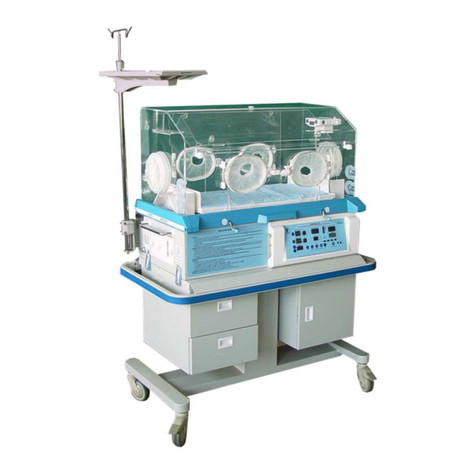
NINGBO DAVID 90 Series User manual

EDITION/REVISION B/0
NINGBO DAVID
R
SERVICE MANUAL
YP-90 YP-90A
YP-90B YP-90 AB
90 SERIES
INFANT INCUBATOR

NINGBO DAVID MEDICAL DEVICE CO., LTD.
ADD: NO.158 DAQING ROAD, SHIPU, NINGBO, ZHEJIANG PROVINCE, CHINA
POST CODE: 315731 FAX: 0086-574-65962111
MARKETING CENTER: NO. 100, JINGHUA ROAD, HI-TECH INDUSTRIAL DEVELOPMENT ZONE,
NINGBO, CHINA
POST CODE: 315000
TEL: 0086-574-87800008, 87800009 FAX: 0086-574-87801111
E-MAIL: [email protected] [email protected]
WEBSITE: http://www.nbdavid.com
EUROPEAN REPRESENTATIVE: SHANGHAI INTERNATIONAL HOLDING CORP. GMBH (EUROPE)
ADD: EIFFESTRASSE 80, 20537 HAMBURG, GERMANY
TEL: 0049-40-2513175 FAX: 0049-40-255726
EDITION/REVISION B/0

SERVICEMANUALFORINFANTINCUBATOR EDITION/REVISION B/0
i
I2
WARRANTY
The product being described in this manual is warranted against defects in materials or
workmanship for one year from the date of shipment, with the following exceptions.
1. All consumable and disposable products are guaranteed to be free from defects upon
shipment only.
2. Calibrations are considered normal maintenance and are not included in the 1-year warranty.
During the warranty period any defective parts other than those listed above will be replaced at no
charge to the customer.
This warranty is rendered void and our company cannot be held liable for conditions resultant
therefrom if:
1. Damage to the unit is incurred as a result of mishandling.
2. The customer fails to maintain the unit in a proper manner.
3. The customer uses any parts, accessories, or fittings not specified or sold by our company.
4. Sale or service is performed by the non-certified service/dealer agency.
This warranty is in lieu of all other warranties, expressed or implied, and our company shall in no
event be liable for incidental or consequential damages including loss of use, property damage, or
personal injury resulting from breach of warranty.
The Accreditation Manual for Hospitals requires each piece of equipment to be tested prior to initial
use and at least annually thereafter. To comply with this standard, we recommend that you participate in
our accreditation Testing compliance Program during the warranty period. This service can be
performed through our company and authorized dealers.
SERVICE
For optimal performance, product service should be performed only by qualified service personnel.
Technical Services representatives can be reached for fixations and are dispatched for required
maintenance by calling 0086-574-87801003, 87800002. Customers outside China should contact their
local factory-authorized distributor for service.

SERVICEMANUALFORINFANTINCUBATOR EDITION/REVISION B/0
ii I2
COMPLEMENTARY NOTICE
Since our company, conducts a continuous product improvement program, circuit and component
improvements are sometimes incorporated into equipment before they can be incorporated into the
printed manuals. This manual contains proprietary information, repairs and authorized modifications
should be performed only by qualified service personnel to maintain your warranty and to avoid creating
safety hazards. We cannot assume responsibility for any conditions affecting the proper operation of this
equipment which may result from unauthorized repair modification. Therefore, some parts used in your
equipment may be different than those which appear in the parts list of this manual. This sometimes
occurs due to difficulty in parts procurement, but does not alter the function of the equipment
The device, accessories and the packaging have to be disposed of waste correctly at the end of the
usage. Please follow Local Ordinances or Regulations for disposal.
TABLE OF DEFINITIONS AND SYMBOLS
TECHNICAL DEFINITIONS
SKIN TEMPERATURE SENSOR: A sensing device including the link with the equipment intended to
measure the infant’s skin temperature.
INCUBATOR TEMPERATURE: Air temperature at a point 10cm above and centered over the mattress
surface.
CONTROL TEMPERATURE: The temperature set at the temperature control.
AVERAGE INCUBATOR TEMPERATURE: The average of the maximum and minimum Incubator
temperatures achieved during Temperature Condition.
STEADY TEMPERATURE CONDITION: A condition which is reached when the temperature does not
vary by more than 1℃over a period of 1 hour.
TEMPERATURE ALARM CHECKOUT STATE: The difference between real temperature and control
temperature is within ±0.5℃and such state lasts for over 10 minutes. The equipment must stay in such
state when check up the alarm about temperature
TEMPERATURE UNIFORMITY: The amount by which the average temperature at each of four points
10cm above the mattress surface differs from the Average incubator Temperature at steady
Temperature Condition. The four points are the centers of four quadrants formed by lines that divide the
width and length of the mattress surface.

SERVICEMANUALFORINFANTINCUBATOR EDITION/REVISION B/0
iii
I2
TEMPERATURE VARIABILITY: The variability of the Incubator Temperature that will be observed over
a one hour period after Incubator Temperature Equilibrium has been reached.
TEMPERATURE RISING TIME: The time required for the Incubator Temperature to rise 11℃, when the
Air Control Temperature is at least 12℃above ambient.
NOTE, IMPORTANT, CAUTION AND WARNING
NOTE: A note is inserted in text to point out procedures or conditions, which may otherwise be
misinterpreted or overlooked. A note may also be used to clarify apparently contradictory or
confusing situations.
IMPORTANT: Similar to a Note but be used where greater emphasis is required.
CAUTION: A caution is inserted in text to call attention of a procedure which, It not followed
exactly, can lead to damage or destruction of the equipment.
WARNING: A warning is inserted in text to call attention to dangerous or hazardous conditions
inherent to the operation, cleaning, and maintenance of the equipment which may result in
personal Injury or death of the operator or patient.

SERVICEMANUALFORINFANTINCUBATOR EDITION/REVISION B/0
SYMBOLS
iv I2
>37℃
Attention, Consult Accompanying Documents.
Class I Equipment Type BF Applied Part
On (Connection to the mains)
Off (Disconnection to the mains)
On (Only For A Part Of Equipment) Off (Only For A Part Of Equipment)
RS-232 Connector
AC Power 220-230V, 50Hz
High temperature warning label Protective Earth (Ground)
Earth (Ground) Weight Limit
Heating Power Indicator Mattress Tilt Direction
Low Water Level
High Water Level
Air Mode Key Baby Mode Key
Silence / Reset Key Keypad Key
Set Up Key Set Down Key
Lower device’s height Temperature override mode
selection key
Raise device’s height Type T Fuse 400mAL/250V
Type F Fuse 5AH/250V Fuse Type F 6.3AH/250V
Type T Fuse 160mAL/250V Type T Fuse 800mAL/250V
Serial Number Date Of Manufacture
CE Marking
Auxiliary mains output, MAX:1.6A
CLASS I
RS-232 220-230V~/50Hz
T 400m
A
L
/
250V
F 6.3
A
H/250
V
F 5AH/250V
T 800m
A
L
/
250V
T 160mAL
/
250V
SN
220-230V~/50Hz MAX:1.6A

SERVICEMANUALFORINFANTINCUBATOR EDITION/REVISION B/0
v
I2
SEASONAL SAFETY CHECK
1. Please clean the plug of power cord at least once a year. Too much dust on plug may cause the fire.
2. The following safety checks should be performed at least every 12 months by a qualified person who
has adequate training, knowledge, and practical experience to perform these tests. The data should be
recorded in an equipment log.
①. Inspect the equipment and accessories for mechanical and functional damage.
②. Inspect the safety relevant labels for legibility.
③. Inspect the fuse to verify compliance with rated current and breaking characteristics.
④. Verify that the device functions properly as described in the instructions for use.
⑤. Test the protection earth resistance according IEC 60601-1:1988 + A1:1991 + A2:1995: Limit
0.1Ω.
⑥. Test the earth leakage current according IEC 60601-1:1988 + A1:1991 + A2:1995: Limit: NC
500μA, SFC: 1000μA.
⑦. Test the enclosure leakage current according to IEC 60601-1:1988 + A1:1991 + A2:1995: Limit:
NC 100μA, SFC: 500μA.
⑧. Test the patient leakage current according IEC 60601-1:1988 + A1:1991 + A2:1995: Limit: for
a.c.: 100μA (BF), for d.c.: 10μA (BF).
⑨. Test the patient leakage current under single fault condition with mains voltage on the applied
part according IEC 60601-1:1988 + A1:1991 + A2:1995: Limit: for a.c.:500μA (BF), for d.c.: 50μA (BF).
⑩. According to the test methods of IEC 60601-1:1988 + A1:1991 + A2:1995, the patient leakage
current (net voltage should be added on the applied part) of the testing device must less than 5000μA.
○
11 . Test the patient auxiliary leakage current according IEC 60601-1:1988 + A1:1991+ A2:1995:
Limit: NC for a.c.: 100μA (BF), for d.c.: 10μA (BF).SFC 500μA (BF), for d.c.: 50μA (BF).

SERVICEMANUALFORINFANTINCUBATOR EDITION/REVISION B/0
vi I2
TABLE OF CONTENTS
SECTION PAGE
1. GENERAL INFORMATION…………………………………………………………………………………1-1
1.1 INTRODUCTION……………………………………………………………………………………………1-1
1.2 DESCRIPTION……………………………………………………………………………………………1-1
1.3 ACCESSORIES……………………………………………………………………………………………1-1
2. INSTALLATION………………………………………………………………………………………………2-1
2.1 UNPACKING………………………………………………………………………………………………2-1
2.2 ASSEMBLING ………………………………………………………………………………………………2-1
2.3 OPERTION CHECKOUT PROCEDURES ………………………………………………………………2-6
3.TECHNICAL INFORMATION………………………………………………………………………………3-1
3.1 SPECIFICATION……………………………………………………………………………………………3-1
3.2 WORKING PRINCIPLE……………………………………………………………………………………3-3
4. PREVENTIVE MAINTENANCE……………………………………………………………………………4-1
4.1 GENERAL……………………………………………………………………………………………………4-1
4.2 CLEANING…………………………………………………………………………………………………4-1
4.3 STERILIZATION……………………………………………………………………………………………4-8
4.4 MAINTAINANCE……………………………………………………………………………………………4-8
5.SERVICE………………………………………………………………………………………………………5-1
5.1 GENERAL……………………………………………………………………………………………………5-1
5.2 REPLACEMENT OF ELDMENT…………………………………………………………………………5-1
5.3 SYSTEM SETTING PROCEDURES……………………………………………………………………5-2
5.4 TROUBLESHOOTING PROCEDURES…………………………………………………………………5-6
6. REPLACEMENT PARTS……………………………………………………………………………………6-1
6.1 GENERAL……………………………………………………………………………………………………6-1
7. DIAGRAMS…………………………………………………………………………………………………7-1
7.1 GENERAL……………………………………………………………………………………………………7-1

SERVICE MANUAL FOR INFANT INCUBATOR EDITION/REVISION B/0
SECTION 1
GENERAL INFORMATION
1.1 INTRODUCTION
This manual provides instructions for installation, maintenance and repair the David Infant
Incubators, Model YP-90,YP-90A, YP-90B, YP-90AB. Among these models, YP-90AB is with all
functions other models have.
This manual is intended for use only by trained, qualified service personnel. Instructions for
the operator of the equipment are provided in a separate operator’s manual.
1.2 DESCRIPTION
Based on YP-90, the Infant Incubator YP-90A added with baby mode , cabinet; the Infant
Incubator YP-90B added the Neonate Bilirubin Phototherapy Equipment; YP-90AB added with
baby mode and the Neonate Bilirubin Phototherapy Equipment, cabinet.
YP-90, YP-90B just have one kind of control mode-air mode, YP-90A, YP-90AB have 2
kinds of control mode- air mode and Baby mode. Optional part :>37℃Temperature Override
Mode, Neonate Bilirubin Phototherapy Equipment , and Vertical Height Adjustment cabinet (VHA
cabinet) . If you donot purchase the optional part, please omit it.
1.3 ACCESSORIES
The following diagram shows the main parts of the Infant Incubator:
Neonate Bilirubin Phototherapy Equipment
I.V. Pole
Baby compartment
Shelf
1-1
I2
Controller
Base
Mobile cabinet

SERVICE MANUAL FOR INFANT INCUBATOR EDITION/REVISION B/0
1-2 I2
DESCRIPTION OF PART EXPLANATION
I.V. Pole A kind of bearing part, which is used for hanging the infusion bottle.
Max. Load: 2Kg
Controller
The core part with two kinds of temperature control modes: air
mode, baby mode, and the optional function :>37°Temperature
Override Mode, and it is used for automatic controlling of heat
output, please refer to section 4 on the user's manual.
Shelf A kind of bearing part, which is used for putting some small objects.
Max. Load: 3.5Kg
Baby compartment
It is used for place the infant inside, including the Acrylic hood,
bassinet, and so on. The bassinet can be tilted at ±12°at the request
of clinical needs. The baby scale is optional part, and the Max. Load
of bassinet is 10 Kg.
Size of mattress: 630mm × 355mm
Base An important part of Infant Incubator, and it is mainly composed of
the Aluminium tank, humidity chamber, air filter, and so on.
Mobile cabinet
A bearing part for the incubator, namely stand, cabinet or VHA
cabinet of the incubator. The standard equipment for YP-90 and YP-
90B is stand, for YP-90A and YP-90AB is cabinet. VHA cabinet is
equipped as an optional part.
Neonate Bilirubin
Phototherapy
Equipment (for YP-90B,
YP-90AB)
It is intended for treating the bilirubin of patient.
This part is mounted on top of Infant Incubator , and its light source
has two kinds: fluorescent lamp and LED lamp, the user can choose
this.
for the Neonate Bilirubin Phototherapy Equipment with fluorescent
lamp, please refer to the user’s manual XHZ-90, while for the
Neonate Bilirubin Phototherapy Equipment with LED lamp, please
refer to the user’s manual XHZ-90L.
NOTE: Size of Infant Incubator: W600×H1550×D1150mm(YP-90、YP-90B)
W650×H1560×D1440mm(YP-90A、YP-90AB)
The distance from the bassinet to the floor: 950mm
Weight of Infant Incubator:65Kg(YP-90)
103Kg(YP-90A)
75Kg(YP-90B)
116Kg(YP-90AB)

SERVICEMANUALFORINFANTINCUBATOR EDITION/REVISION B/0
SECTION 2
INSTALLATION
2.1 UNPACKING
Generally, the Infant Incubator is usually packed to two cartons: main body and fixed cabinet or
Vertical Height Adjustment cabinet(VHA cabinet). When taking out the equipment from the cartons, take
care not to damage the spare parts of the Infant Incubator.
2.2 ASSEMBLING
At least two professionals are required to do the installation of the Infant Incubator with spanners.
1. Install the main body onto the fixed stand/cabinet or Vertical Height Adjustment cabinet
A. The installation of main body onto the fixed stand/ cabinet
a. Assembling of fixed stand
1). See figure 2.1, fixed Connecting crosspiece to Left stand and Right stand with Hexagon bolt,
Spring Washer, Flat Washer, external teeth serrated lock washer.
2). See figure 2.1, Inverting Square frame, place the fixed Left and Right stand on Square frame, and
make the bolt and flat washer through the inner board of left stand from the bottom of t Square frame, and
make the Left stand connect Square frame, and fix the outer side of left stand on the frame with bolt,
Spring Washer, Flat Washer. Installation of the right stand is as same as the Left stand.
3). Connect the casters and left and right stand firmly with spring washer 12, flat washer 12
respectively.
NOTE: The wheels with brakes should be installed on the front of stand (longer part of stand is the
front part). Wheel
Hex Nut M6
Spring washer 6
Flat washe
r
6
Hex head screw M6-18
Square frame
Spring washer
8
Flat washe
r
8
Hex head screw M8-20
Connecting crosspiece
Right stand
Spring washer 12
Flat washe
r
12
Inboard plate
Inboard plate
Flat washe
r
6
Spring washer 6
Hex head screw M6-18
Flat washe
r
6
Left stand
FIGURE 2.1
2-1
I2

SERVICEMANUALFORINFANTINCUBATOR EDITION/REVISION B/0
b. Install the main body onto the fixed stand
1). See figure 2.2, lock the casters with brake, and put the main body onto the fixed, and connect it
with the lock mechanism on two sides of stand.
Main body of Incubator
2-2
I2
Lock mechanism
II
Fixed Stand
I
(EnlargedfigureI) (EnlargedfigureII)
1
2
wheel unlocked wheel locked hang on the lock close the lock spanner
NOTE: See Enlarged figure I, lock the casters as the arrow 1 indicates, and unlock the casters as
the arrow 2 indicates.
See Enlarged figure II, hang on the lock , and close the lock spanner.
FIGURE 2.2

SERVICEMANUALFORINFANTINCUBATOR EDITION/REVISION B/0
B. The installation of main body onto the cabinet
a. As figure 2.3 indicates, put on the spring washer, flat washer on the casters, and then connect with
cabinet firmly. Note: The caster with brake must be installed in front of the cabinet.
FIGURE 2.3
b. As figure 2.2 indicates, lock the casters with brake, see figure 2.4, and put the guard rail and main
body on the cabinet, and then fix them with the lock mechanism on two sides of cabinet.
Main body of incubator
Guard rail
Lock mechanism
Cabinet
FIGURE 2.4
2-3
I2

SERVICEMANUALFORINFANTINCUBATOR EDITION/REVISION B/0
C. Install the main body onto the Vertical Height Adjustment Stand
a. The method of installation casters is same as part B.
b. The method of installation main body, guard rail on the Vertical Height Adjustment cabinet same as
part B.
c. After installation, insert the power cord on the right side of Vertical Height Adjustment cabinet into
the power socket in figure 4.2.
2-4
I2
Main body of incubator
Power cord
Guard rail
Lock mechanism
The VHA Stand
FIGURE 2.5
The guard rail ensure grounding through bolt,therefore, fixing the guard
railon the cabinet with bolts.
WARNING
Firm the main body onto the fixed cabinet or Vertical Height Adjustment cabinet with lock
mechanism. If not, it will cause the main body to deviate from the fixed cabinet or Vertical
Height Adjustment cabinet when the cabinet tilts, especially when the hood is open.
2. Install the NEONATE BILIRUBIN PHOTOTHERAPY EQUIPMENT, I.V. Pole and shelf
A. Install the NEONATE BILIRUBIN PHOTOTHERAPY EQUIPMENT
Please refer to the method of installation for incubator mounted PHOTOTHERAPY unit XHZ-90 and
XHZ-90L in the accompanying documents.
B. Install I.V. Pole
1) Install the I.V. Pole beside the incubator as figure 2.6 indicates, and then adjust the hook to a
proper height, fix it with the turnbuckle.

SERVICEMANUALFORINFANTINCUBATOR EDITION/REVISION B/0
Hexagon bolt
2-5
I2
Fixed seat
Infusion rod
Step 1: loose the hexagon bolts on the fixed seat with spanner, insert the I.V. Pole to the bottom, and fix
the bolt to fasten the infusion rod.
Hook For Infusion Rod
Hexagon Bolt
Step 2: Tight the hexagon bolts on the
bottom of infusion rod to fix the rod. Step 3: Rotate the hook into the I.V. Pole,
and then tighten the hexagon bolts.
FIGURE 2.6
C. Install shelf
Unscrew the hexagon bolts on the fixed seat for shelf, See figure 2.7, and put on the fixed seat on the
infusion rod, see Enlarged figure A, to make sure the top of fixed seat and the position limit mark on the
rod is on same level. And then reinstall the hexagon bolt on the fixed seat.
ENLARGED FIGURE A
Infusion Rod position limit mark
A
Hexagon Bolt
Fixed Seat
NOTE: when installing the shelf, the side with note label should face the front of incubator.
FIGURE 2.7
3. Insert the power cord
Insert the power cord into the socket of general power supply on the right side of main body; For the
VHA stand, Insert the power cord into the socket of general power supply on the VHA stand.
Check the WARMER according to the instruction in section 2.3.

SERVICEMANUALFORINFANTINCUBATOR EDITION/REVISION B/0
2-6
I2
2.3 OPERATION CHECKOUT PROCEDURE
WARNING
1. Please stop using this model once some function lost or the spare parts for front
access panel is loose.
2. set temperature must be high 3 than ambient temperature. And then you can℃
proceed this checkout procedure.
Please proceed the following checkout procedure each time before operation.
A. Check caster
Check whether the caster can drop when lifting the radiant warmer 2cm above the ground. The drop
of the caster will cause danger during transporting.
IMPORTANT: At least two persons are required, one lifts the warmers, and the other has to check
the casters. It needs Min. 140Kg to light the whole unit. Please support the stand with
block to avoid the warmer inclining if the casters drop.
B. START-UP THE CONTROLLER
Turn on the switch of the main power supply and controller, the controller gives sound “Ding”, at the
same time, the Set Temperature indicator does not indicate, while the Air Temperature indicator and
Skin Temperature indicator indicates“--.-”, it means the controller is doing self-test automatically for 5s.
After then, the Air Temperature indicator will displays air temperature, the Skin Temperature indicator
displays the baby temperature, and Set Temperature indicator displays the former set value, and the
controller can enter into the control mode automatically before turning off, and the relevant mode light will
be on.
C. CHECK POWER FAILURE ALARM
Pull off the power cord of whole unit, the Power failure alarm should active, and the “Power” light will
flash with continuous audible sound.
This operation is used for checking if the power failure is normal or not. Insert the power cord again
after finishing checking.
IMPORTANT: Make sure that the rechargeable battery is full before usage. If not full, it may cause
the power failure without the alarming indication. If full, and there is no any
indication after disconnecting the main power supply, please refer to the authorized
and qualified service personnel.
D. CHECK HEATER
Control the environment temperature at 21℃~ 26℃, and choose the Air Mode, and set the
temperature at 33.0 ℃, and all heat power indicator are on, and heater will output heat completely.
NOTE: When the incubator works under the set state, and continue the following operation
procedure.

SERVICEMANUALFORINFANTINCUBATOR EDITION/REVISION B/0
E. CHECK THE ACCURACY OF TEMPERATURE CONTROL
Select the Air Mode, and set the air temperature at 36℃, after the air temperature enters into the
STEADY TEMPERATURE CONDITION, put the calibrated temperature measuring device on the position
above 10cm from the center of mattress to measure the air temperature, compared with the indicated air
temperature to check whether the deviation between them is within 0.8℃.
F. CHECK BABY MODE
Opening
2-7
I2
Arrow Sensor socket
The arrow sign on the plug should aim to the opening on the sensor socket so that the sensor is
inserted correctly.
1. Insert or pull out the skin sensor, you must hold the plug of skin sensor,
pulling the leads is forbidden.
2. Please do not bend the connection of sensor.
When the Air Mode works stably, change it into the Baby Mode, set temperature at 37℃. Put the
skin sensor on the center position, and the incubator will give alarm after a while. The “Sensor” alarm
light will flash with continuous audible sound, and the Set Temperature indicator will show alarm code
E0.8.
Pull off the skin temperature sensor, the sensor failure alarm should active. The “Sensor”
alarm light will flash with continuous audible sound, and the Set Temperature indicator will show alarm
code E0.5.
G. CHECK PRECISION OF SKIN TEMPERATURE SENSOR
Put the skin temperature sensor with the mercury thermograph for the accuracy with ±0.1ºC into the
water cup with the temperature as 30ºC±5ºC. Make the probe of the skin temperature sensor and the
mercury ball as closely as possible and stir enough, then read the value of mercury thermograph.
Compare the value of the skin temperature sensor and the mercury thermograph, and the deviation must
be within 0.5ºC.
NOTE: Please check again if the accuracy of the skin temperature sensor exceeds the
permissibility deviation. Please let the authorized and qualified service personnel service
machine if the accuracy the skin temperature sensor exceeds the permissibility of
deviation again.

SERVICEMANUALFORINFANTINCUBATOR EDITION/REVISION B/0
H. CHECK FAN MOTOR ALARM
Block the inlet port and outlet port on the left and right side of main deck, after several minutes, the
device gives alarms, the “Fan” alarm light will flash with continuous audible sound, and the Set
Temperature indicator will show alarm code E0.7.
Turn off the power supply of controller, and pull off the power cord, and take out the controller.
Reconnect the power cord, and hold the fan slightly, and turn on the switch of controller, and the fan
motor alarm occurs, the “Fan” alarm light will flash with continuous audible sound, and the Set
Temperature indicator will show alarm code E0.9.
WARNING: The temperature of heater inside controller is too high, and you can
remove the controller or touch the heater after the unit is switched off at
least 45min to avoid the burnt.
I. CHECK OVER-TEMPERATURE ALARM
In Air Mode, enter into the working state, press Up, Down and Silence/Reset key, there is no
indication on the Set Temperature indicator, and the heat power indicator is on in full, and the controller
has entered into the overtemp checkout state, and when the incubator temperature is less than 38.0 ,℃
the over-temperature alarm should active. The “Over” light should flash with continuous audible sound,
and the Set Temperature indicator should show alarm code E0.6. Under the state of >37℃Override
Mode, enter into the working state, press Up, Down and Silence/Reset key, there is no indication on the
Set Temperature indicator, and the heat power indicator is on in full, and the controller has entered into
the overtemp checkout state, and when the incubator temperature is less than 40.0℃, the
over-temperature alarm should active. The “Over” light should flash with continuous audible sound, and
the Set Temperature indicator should show alarm code E0.6.
In Baby Mode, press Up, Down and Silence/Reset key, there is no indication on the Set
Temperature indicator, and the heat power indicator is on in full, and the controller has entered into the
overtemp checkout state, and when the incubator temperature is less than 40.0 , the℃over-temperature
alarm should active. The “Over” light should flash with continuous audible sound, and the Set
Temperature indicator should show alarm code E0.6.
J. CHECK DEVIATION ALARM
In Air Mode, close all door and panels, set the temperature at 32 ºC. Enter TEMPERATURE ALARM
CHECKOUT STATE, fan into the hot air inside the hood. When the Air Temperature indicator indicates
35.1ºC, the HIGH deviation alarm will active. The “High” light should flash with continuous audible sound,
and the Set Temperature indicator should show alarm code E1.0; Set the temperature at 35℃, after the
device enters into the TEMPERATURE ALARM CHECKOUT STATE, open the front access panel, when
the Air Temperature indicator indicates 31.9 ºC, the low deviation alarm should active. The “Low” light
should flash with continuous audible sound, and the Set Temperature indicator should show alarm code
E1.1.
2-8
I2

SERVICEMANUALFORINFANTINCUBATOR EDITION/REVISION B/0
NOTE: If the system can not enter into the TEMPERATURE ALARM CHECKOUT STATE or the air
temperature does vary within ±3℃than the setting temperature, the deviation alarm
can not occur.
In Baby Mode, set the temperature at 35 ºC. Enter TEMPERATURE ALARM CHECKOUT STATE,
put the skin sensor into the water cup at 37 ºC. When the skin temperature indicates 36.1 ºC, the high
deviation alarm will active. The “High” light should flash with continuous audible sound, and the Set
Temperature indicator should show alarm code E1.0; Set the temperature at 35℃, after the device
enters into the TEMPERATURE ALARM CHECKOUT STATE, put the skin sensor into the water cup at
temperature 33℃, when the skin temperature indicates to 33.9ºC, the low deviation alarm should active.
The “Low” light should flash with continuous audible sound, and the Set Temperature indicator should
show alarm code E1.1.
NOTE: If the system can not enter into the TEMPERATURE ALARM CHECKOUT STATE or the
baby temperature does vary within ±1℃than the setting temperature, the deviation
alarm can not occur.
K. CHECK THE HOOD OPERATION
See the following figure, raise the hood until you hear the sound “kata”, and the hood is in the lock
state. Press the lock downward as the arrow indicates so that the hood can return the original position.
CAUTION: Before raise the hood, ensure all accessories is disconnected to avoid interfere
operating.
2-9
I2
Disconnect the skin sensor, slowly tilt the pressing the lock as the arrow indicates, and close
Hood back until the Hood locks in place. the hood slowly.

SERVICEMANUALFORINFANTINCUBATOR EDITION/REVISION B/0
L. CHECK FRONT ACCESS PANEL
The Pawl Latch
LOCKED UNLOCK
Rotate the panel Latches and open the Access Pane to the full open position (rotate downward).
Close the Access Panel and rotate both latches until they are fully locked. Both latches must be fully
locked to avoid accidental opening of the panel.
M. CHECK IRIS ENTRY PORTS
Rotate the outer ring of each entry Port, the port should be open and close as rotation is continued
through 360 degree.
N. CHECK THE LATCH AND GASKET OF ACCESS DOOR
Press on-off of each access door to open it automatically and check the seal of gaskets.
2-10
I2
This manual suits for next models
4
Table of contents
Other NINGBO DAVID Accessories manuals
