PerfectSense PS-PCL24-R User manual

PS-HDTC24-R:
1000 sq ft 360° Presence Sensor
HDIR and Ultrasonic Technology
Ceiling Mount | Low Voltage
Phone: 218.828.3700 www.nexlight.com Fax: 218.824.1568
Electrical:
Power Requirements: 24VDC, from powerpack
Current Consumption: 30mA
Output: 24VDC active high logic control signal
with short circuit protection
Isolated Relays: 2 SPDT 1 Amp, 30 VDC Form C
Wiring Diagram: See Fig. 2
Controls:
HDIR Sensitivity: 0-100% (Factory Set 50%)
Ultrasonic Sensitivity: 0-100% (Factory Set 50%)
Light Sensor: 20-320 Foot Candles (Factory Disabled)
Detection Range: See Fig. 1
Load Rating: Controls Class 2 Power Pack
Housing Material: High-Impact ABS
Color: White
Environment Temperature: 14ºF to 122ºF
Humidity: 0-95% Non Condensing
Installation: See Install Instructions
Dimensions: Diameter 4.33 in
Height 2.2 in
Supported with limited 5-year warranty
Title 24 Compliant
Meets ASHRAE 90.1 requirements
PerfectSense®
© 2015 NexLight Lighting Controls, All Rights Reserved. 1
Overview:
The PS-HDTC24-R is a low voltage High Definition Passive
Infrared (HDIR) and Ultrasonic (US) Presence Sensor designed
to work with any PerfectSense power pack, to automatically
control lighting in applications where minor motion is domi-
nant and a dual technology sensor is necessary. Utilizes
patented industry best HDIR infrared sensing technology (864
field of view points) that provides superior micro-movement
detection. Dual Form C Relays are present on the sensor to
allow for integration to NexLight’s 2-wire system and
HVAC/BMS Systems. The sensor turns the lights on and keeps
them on while occupancy is detected and will turn the lights
off after the delayed-off time has expired.
Operation:
Single-tech Mode: Only one technology (dip switch select-
able) is active in this mode. Motion detection by the selected
technology will turn ON the lights as well as keep them ON.
When motion is not detected, the lights will turn OFF after the
delayed-off time.
Multi-tech Mode:
Mode 1: Switch A1 is OFF and Switch A2 is OFF: PIR detection
will turn lights ON in this mode, motion detection by either
technology will keep the lights ON. If neither technology
detects motion, the lights turn off after the delayed-OFF time.
Mode 2: Switch A1 is OFF and Switch A2 is ON (this is the
default mode): Detection by either technology will turn the
lights ON as well as keep them ON. If neither technology
detects motion, the lights will turn OFF after the delayed-OFF
time.
Walk-Through Mode: useful when a room is momentarily
occupied, like a storage area, When a person enters the room,
the lights turn on. If the person leaves the room before the 2.5
minute walk-through timer expires, the sensor will turn the
lights OFF. If the person stays in the room longer than 2.5
minutes the sensor will proceed to standard operation.
Daylight Sensor: The integrated daylight sensor allows for
ambient light override functionality. If this setting is enabled,
the controlled lighting load will only turn on if the ambient
light present is less than the preset level.
LED Indication: The integrated LED indication lights will flash
when motion is detected. This can be disabled using the LED
Disable switch setting in the control console of the sensor. A
Red flash indicates motion sensing by HDIR, while a Green
flash indicates motion sensing by Ultrasonic.
Features:
• 1000 sq ft range
• Patented HDIR 8-element Sensor
• 864 Optical Field-of View Pattern
• Dual Technology
• Single Technology selectable
• 360° Coverage Pattern
• Superior RF immunity
• Adjustable Time Delay (30 sec – 30 min)
• Walk-Through Mode
• Daylight Override Mode
• Mounts in drop ceilings and solid ceilings
• LED indication of occupancy sensing

Phone: 218.828.3700 www.nexlight.com Fax: 218.824.1568
© 2015 NexLight Lighting Controls, All Rights Reserved. 2
Sensor Adjustments Console:
Setstheinfraredrange
Rangesetting
FullCCW=min.(OFF)
FullCW=max.
Passive Infrared Adjustment
Delayed-OFFtime
Daylight Sensor Adjustment
Factory default setting is disabled. If installed
location calls for the use of daylight sensor this is
the adjustment for control of required ambient
light levels necessary to disable the automatic
ON control of the sensor when detecting occu-
pancy. NOTE: The daylight sensor function is not
applicable in rooms using manual ON control.
All aspects of sensor operation can be adjusted here.
View of adjustments when cover is removed. Dip
Switch setting table below illustrates how to enable
and disable sensor functions.
Each time motion is detected, the lights remain
activated for a pre-set time, which is set by the
Off-time adjustment. The fully counter-clockwise
setting (30seconds) can be used for testing. If
motion is detected during the ON time, the timer
resets and lights will remain on until the full
PIR sensitivity can be dialed up or down to meet
the exact needs of any space. This adjustment is
helpful to ensure detection in all areas during a
walk test.
Setstheultrasonicrange
Rangesetting
FullCCW=min.(OFF)
FullCW=max.
Ultrasonic Adjustment
Ultrasonic sensitivity can be dialed up or down to
meet the exact needs of any space. This adjust-
ment is helpful to ensure detection in all areas
during a walk test.
SWITCHFUNCTI ONS
Ba nkAOFFON
Single Multi T
ech Mode Multi Tech Single Tech/--
Single Tech (A1 ON) PIR Ultrasonic
Walk Through Mode Walk Through Enable Walk Through Disable
---
Ba nkB
Light Mode Lights Adjust Enable Lights Adjust Disable
LEDs Mode LEDs Enabled LEDs Disable
Test Mode OFF ON OFF = Enter/Exit Test Mode
N/A N/A N/A
SWI TCHS ETTI NG S
SWITCH
A1
A2*
A3
A4
B1
B2
B3
B4
Multi-Tech (A1 OFF) Multi-Tech mode1 Multi-Tech mode2
DIP SWITCH SETTINGS
N/A N/A N/A

Note: Sensor tested using NEMA WD 7-
2011 Occupancy Motion Sensors Standard

Phone: 218.828.3700 www.nexlight.com Fax: 218.824.1568
© 2015 NexLight Lighting Controls, All Rights Reserved. 4
# Element Orientation Detection Area Description
8 Element IR of
PerfectSense
PS-HDTC24-R
! 864 optical view patterns,
each cluster of 8-element
pattern makes detecting
very fine body movement
possible.
! 360-degree coverage with
circular area, good
repeatability.
! Detect movements 20
degree across the optical
zone.
4 Element IR of
Ordinary Product
! 224 optical view patterns.
! Detection coverage is not
full circle.
! Many blind spots.
2 Element IR of
Ordinary Product
(Industry Standard)
! 62 optical view patterns.
! An ellipse shape detection
coverage, not full circle.
! Detect movement 40
degree across optical
zone.
Sensor Technology Comparison
HDIR technology significantly surpasses known boundaries of IR sensor technology. Extending the capability of IR to new
levels of accuracy through a combination of patented sensor hardware and logic algorithms. The power behind this innova-
tion originates from a proprietary 8-element pyros infrared element that eclipses current competitive sensor logic technolo-
gies. Eight-Hundred and Sixty-Four (864) optical view patterns are achieved, delivering unmatched sensitivity for minor
motion events like hand and finger movements. Paired with ultrasonic technology for a complete solution designed to meet
the demands of Title 24 and ASHRAE 90.1.

DETECTION AND ACTIVATION:
When a person enters a room, the sensor detects major body motion
and turns the light on. The light is kept on even as smaller body
movement is detected. This sensor’s detection sequence logic (DSL)
minimizes false triggering by continuously analyzes the motion
detection signal and adjusts internal operation to maximize the
and electrical noise.
DESCRIPTION:
OPERATION OF SENSOR
Test Mode: This mode is used to set the Delayed-OFF Time to 5 seconds for
while in test mode.
1. Ensure Power is On
2. Remove the cover from the Operation Control Console
defaulted to the OFF position.
4. To enter Test Mode, move the switch from OFF to ON and then back to
OFF. IF B3 is already in the ON position, test mode can be entered by just
moving it back to the OFF position.
Notes for Test Mode:
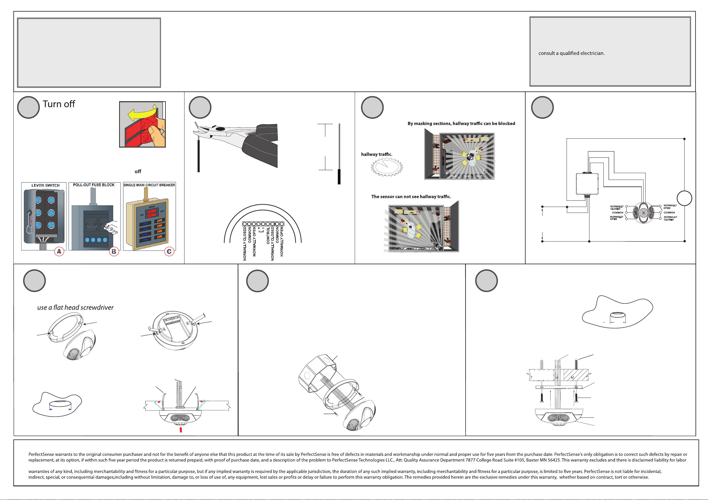
DETECTION AREA
TESTING THE SENSOR
Presence Sensor designed to work with any PerfectSense power pack, to
automatically control lighting in applications where minor motion is dominant
and a dual technology sensor is necessary. Utilizes patented industry best
superior micro-movement detection. Dual Form C Relays are present on the
sensor to allow for integration to NexLight’s 2-wire system and HVAC/BMS
Systems. The sensor turns the lights on and keeps them on while occupancy is
There is a daylight sensor built into the sensor to allow for ambient light
used, the controlled lighting load will only turn on if the ambient light present
is less than the desired setting.
INSTALLATION:
See the back of this installation manual for installation instructions. The sensor
is fully operational after 30 seconds of powering up the device.
Single-Tech Mode: Only one technology (dip switch selectable) is active in
this mode. Motion detection by the selected technology will turn ON the
lights as well as keep them ON. When motion is not detected, the lights will
Multi-Tech Mode:
Mode 1: Switch A1 is OFF and Switch A2 is OFF: PIR detection will turn
lights ON in this mode, motion detection by either technology will keep the
delayed-OFF time.
Mode 2: Switch A1 is OFF and Switch A2 is ON (this is the default mode):
Detection by either technology will turn the lights ON as well as keep them
ON. If neither technology detects motion, the lights will turn OFF after the
delayed-OFF time.
Delayed-OFF Time: The sensor is designed to turn the lights OFF if no black
twist knob designated for timer inside the control console. Dependent
upon environmental conditions and occupancy patterns, the adapting
patterns will modify the delayed-OFF time to match the parameters of each
installation.
Walk-Through Mode: The walk-through feature is useful when a room is
momentarily occupied, such as a storage room. When a person enters the
room, the lights will turn on and stay on for 2.5 minutes. After 2.5
Scenario A: If motion is detected within 10 seconds of the lights shutting
Scenario B: If no motion is detected within 10 seconds of the lights it sees
detection the lights will turn on for 2.5 minutes.
Daylight Sensor: To enable daylight sensor operation, set Dip Switch 1 in
Bank B to OFF. This puts the sensor in a stand-by mode when the natural
light level exceeds the selected Foot Candles (FC) level inhibiting the lights
from turning ON.
LED Operation: The Sensor has two LED indicators that, when enabled, will
has been detected by Infrared Technology, Green indicates Ultrasonic.
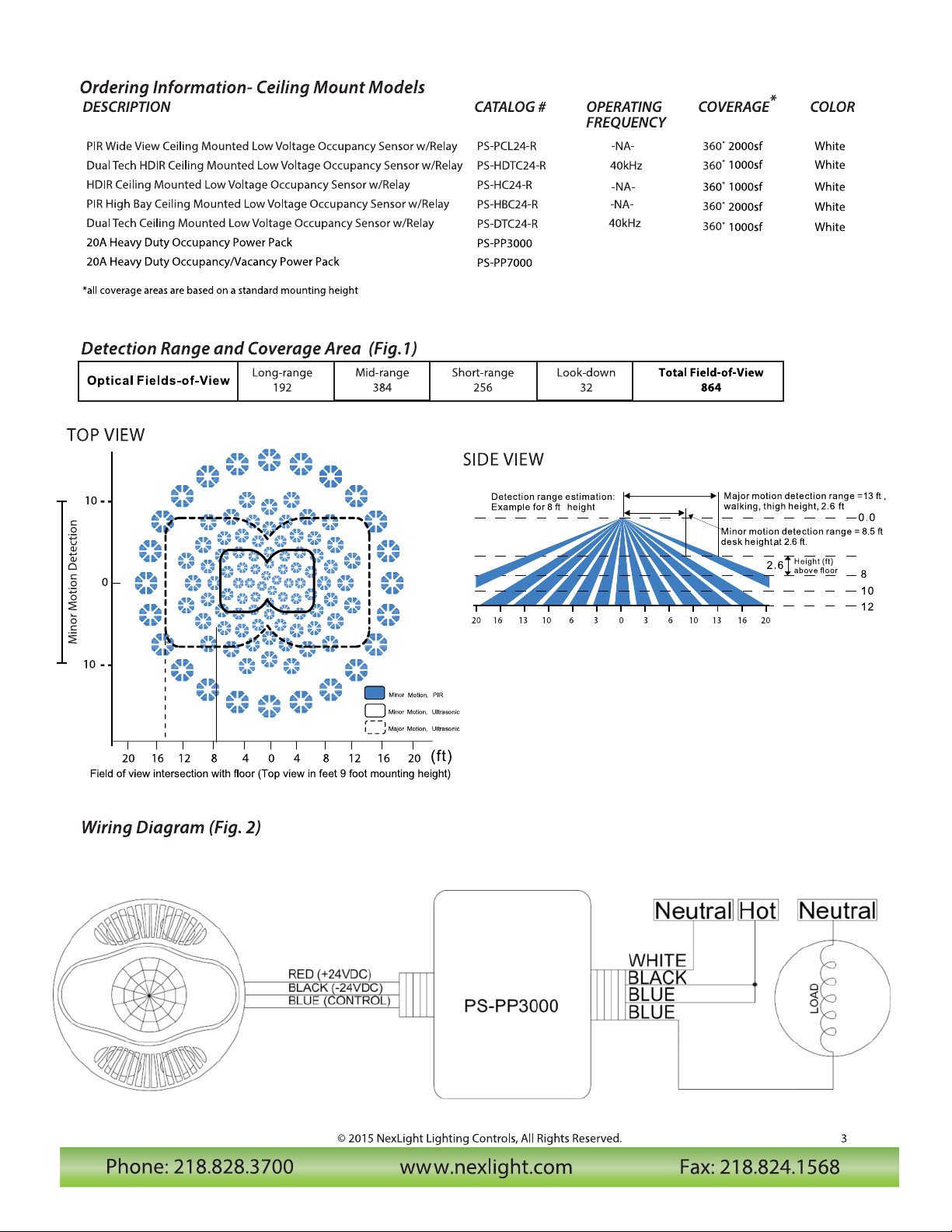
TOP VIEW
Field of view intersection with floor (Top view in feet 9 foot mounting height)
0
20
1240 8 1641220 16 8
10
10
Minor Motion Detection
(ft)
Detection range estimation:
Example for 8 ft height
Major motion detection range =13 ft ,
walking, thigh height, 2.6 ft
0.0
2.6 8
12
Height (ft)
above floor
10
Minor motion detection range = 8.5 ft
desk height,at 2.6 ft.
SIDE VIEW
0 3 6 10 13 16 2020 16 13 10 6 3
Minor Motion Ultrasonic,
Major Motion Ultrasonic,
Motion PIR,
Minor
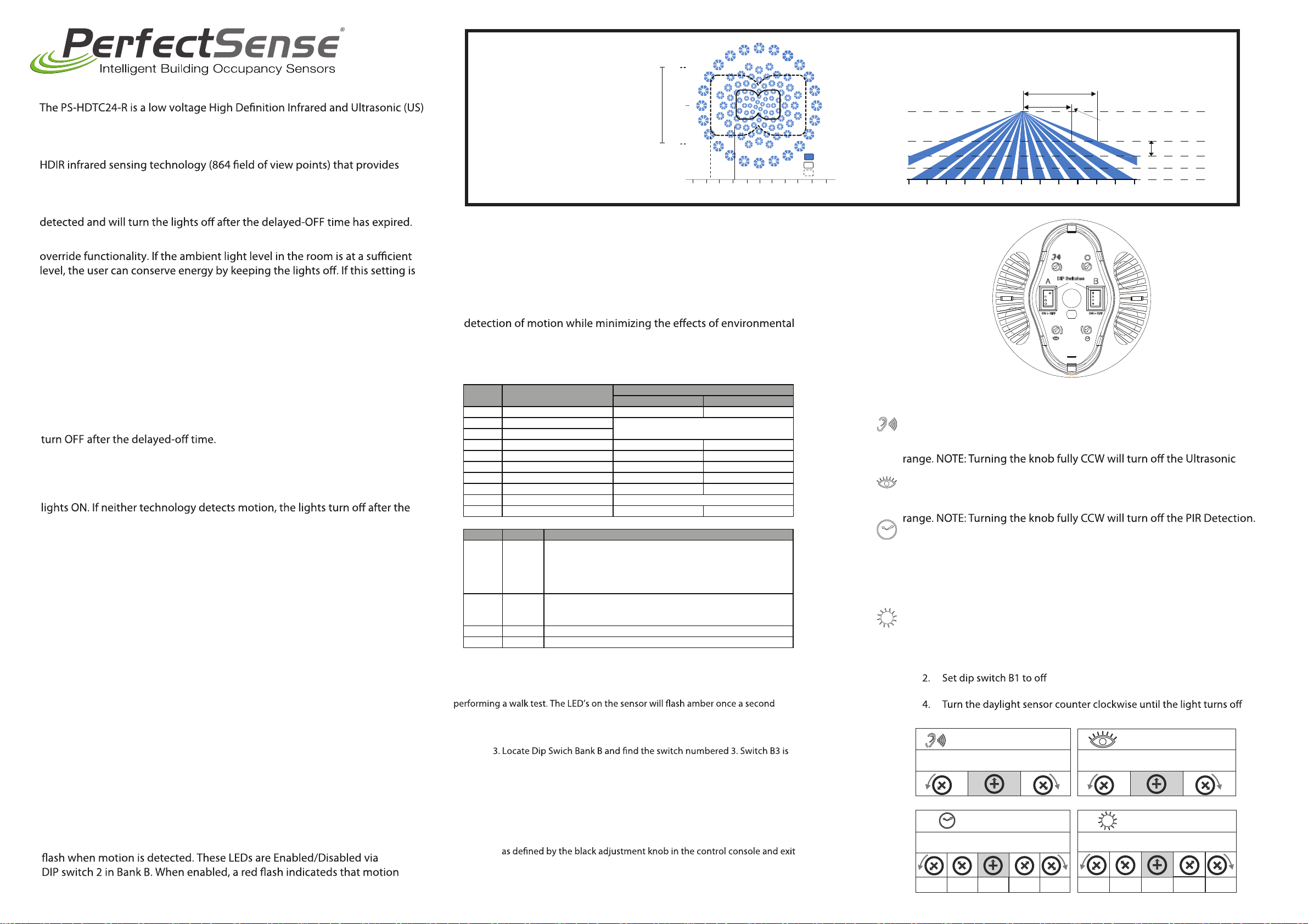
OPERATION MODE ADJUSTMENT
Switch Function
Settings
Off On
Bank A
A1 Multi/Single Technology Features enabled by the combination of
A1 & A2 are shown in the table below.
A2 Technology Activated
A3 N/A
A4 Walk-Thru Mode Walk-Thru Enabled Normal Occupancy
Bank B
B1 Daylight Sensor Enabled Disabled
B2 LED Indicator Enabled Disabled
B3 Test Mode Off-On-Off (Toggle Enter/Exit)
B4 N/A
A1 A2 Feature
Off Off PIR technology turns light on; however, motion detection
by either technology will keep the light on. If neither
technology detects motion, the light turns off after the
Delay-Off time. [Choose this option to reduce false
activation due to ultrasonic technology.]
Off On PIR or Ultrasonic technology turns light on and keeps light
on. If neither technology detects motion, the light turns off
after the Delay-Off time. [Default]
On Off Only PIR technology is active.
On On Only Ultrasonic technology is active.
Infrared Range
Range setting
Full CCW = min.(OFF)
Full CW = max.
Ultrasonic Range
Range setting
Full CCW = min.(OFF)
Full CW = max.
Factory Default Factory Default
Delayed-OFF time
30sec 5min 10min 20min 30min
Full CCW = min.(5 sec.)
Full CW = max.(30 min.)
Factory Default
Daylight Sensor
20 FC 40 FC 80 FC 160 FC 320 FC
Full CCW = Lights stay OFF
Full CW = Lights always turn ON (NO daylight override)
Factory Default
SETTINGS:
(Fig. Operation control console)
All aspects of sensor operation can be adjusted here
a. Ultrasonic Adjustment- For maximum range, set fully clockwise (CW).
If reduced range is required, then turn counterclockwise (CCW) and test
Detection.
b. Infrared Adjustment- For maximum range, set fully clockwise (CW). If
reduced range is required, then turn counterclockwise (CCW) and test
c. Delayed-OFF Time Adjustment: Each time motion is detected, the
load remains activated for a pre-set time, which is set by the
Delayed-OFF Time Adjustment, The fully CCW setting (30 seconds) can
be used for testing. The fully clockwise setting is 30 Minutes. If motion is
detected during the ON time, then the load remains activated until the
full ON time has passed since the latest motion detection.
d. Daylight Sensor Adjustment: This level needs to be set in a room
where natural light is at the desired level for the lighting load to not be
turned on. The sensor will still see motion (indicated by the red LEDS)
1. Set the daylight sensor knob to fully counter clockwise (lowest level)
3. Turn the daylight sensor knob clockwise until the light turns on.
5. This will be the setting
1. The Delayed-OFF Time will remain in the 5 second test mode for 15
minutes. It will then automatically reset to the Delayed -OFF Time setting
test mode.
2. To manually take the sensor out of the test mode, move switch B3 from
OFF to ON and back to OFF again.
AB

Hot (Black)
Neutral (White)
Load
Black
Blue
Blue
White
Black
White
Line
120/277/347VAC
60Hz
(typical power pack shown wire color may vary)
Red (24V+)
Blue (CTL)
Black (24V-)
Prepare and connect wires
1/2"
(1.3 cm)
Strip wire
(measure bare wire here)
Cut
(if necessary)
for removal of this product or reinstallation. This warranty is void if this product is installed improperly or in an improper environment, overloaded, misused, opened, abused, or altered in any manner, or is not used under normal operating conditions or not in accordance with any labels or instructions. There are no other or implied
LIMITED 5 YEAR WARRANTY AND EXCLUSIONS
INSTALLATION INSTRUCTIONS
WARNING:
TO AVOID FIRE, SHOCK, OR DEATH;TURN OFF POWER
at circuit breaker or fuse and test that power is before wiring!
power at
circuit breaker
Option B. Junction box
1. Use two #8 32 screws (not supplied) to fasten the base
ring tothe ceiling.
#8-32 Screws
(not supplied)
Octagon Box
4" x 1 1/2" deep
Low-Voltage
Wires
Insert wires intocorrect terminalblocks and tighten.
Be sure to double check correct wiring connections!
Power
Pack
Wiring to power pack
By masking sections,
you can block hallway traffic
Mask
Masking is not required in a corner mounting application.
Select mounting location
Use the included PIR Mask
when sensor location may
cause false ON’s due to
(For best results mount at least 6 feet away from air vents)
1
Option C. Base ring w/ mounting anchors
Low-Voltage Wires
Wallboard
Ceiling
Sensor
Base Ring
Sensor Base
Mounting Screws
(2 places)
Sensor Front Cover
Mounting Anchors
1. cut 2” hole in ceiling
2. mount sensor
2 in
5
2 3 4
Included Parts List:
Sensor (1) Base mounting ring (1)
Wall Anchors (3) Spring mounting clip (2)
PIR detection Mask (1) 7/8” Wall anchor screw (3)
Tools required for install:
Slotted/Phillips Screwdriver Wire Stripper
Pencil Wire Cutters
Hole Saw
FCC COMPLIANCE STATEMENT:
This device complies with part 15 and part 18 of the FCC rules. Operation is subject to the following two conditions: (1) This device must not
cause harmful interference, and (2) This device must accept any interference received, including interference that may cause undesired operation.
WARNINGS AND CAUTIONS:
•To be installed and/or used in accordance with appropriate
electrical codes and regulations.
• If you are unsure about any part of these instructions,
• Sensors must be mounted on a vibration free surface.
• All sensors must be mounted at least 6 feet away from air vents.
• Do not mount sensors closer than 10 feet from each other.
• Do not touch the surface of the PIR lens. Clean outer surface only.
2. Align the sensor’s two eyelets with the base ring’s two hooks.
3. Press the sensor onto the base ring.
5
Option A. Drop ceiling w/ mounting clips
A. remove mounting ring
3.375 in
Low Voltage Wires
Wallboard
Ceiling
Terminal Block
Connections
Mounting
Clips
B. install clips
C. cut 3.375” hole
in ceiling
D. mount sensor
2
11
5
NORMALLY CLOSED
NORMALLY OPEN
COMMON
NORMALLY OPEN
+
_
CONTROL
COMMON
NORMALLY CLOSED
CLOSED
NORMALLY
COMMON
NORMALLY
OPEN
NORMALLY
COMMON
NORMALLY
OPEN
CLOSED
24 Vdc

Phone: 218.828.3700 www.nexlight.com Fax: 218.824.1568
© 2015 NexLight Lighting Controls, All Rights Reserved. 4
# Element Orientation Detection Area Description
8 Element IR of
PerfectSense
PS-HDTC24-R
!864 optical view patterns,
each cluster of 8-element
pattern makes detecting
very fine body movement
possible.
!360-degree coverage with
circular area, good
repeatability.
!Detect movements 20
degree across the optical
zone.
4 Element IR of
Ordinary Product
!224 optical view patterns.
!Detection coverage is not
full circle.
!Many blind spots.
2 Element IR of
Ordinary Product
(Industry Standard)
!62 optical view patterns.
!An ellipse shape detection
coverage, not full circle.
!Detect movement 40
degree across optical
zone.
Sensor Technology Comparison
HDIR technology signicantly surpasses known boundaries of IR sensor technology. Extending the capability of IR to new
levels of accuracy through a combination of patented sensor hardware and logic algorithms. The power behind this innova-
tion originates from a proprietary 8-element pyros infrared element that eclipses current competitive sensor logic technolo-
gies. Eight-Hundred and Sixty-Four (864) optical view patterns are achieved, delivering unmatched sensitivity for minor
motion events like hand and nger movements. Paired with ultrasonic technology for a complete solution designed to meet
the demands of Title 24 and ASHRAE 90.1.
This manual suits for next models
6
Table of contents
Other PerfectSense Accessories manuals