Niobrara QUCM-OE Assembly instructions

QUCM Modbus ASCII Modem Application Manual
QUCM Modem Dialer
Installation and Programming Manual
This Manual describes the QUCM application for interfacing remote Modbus and PowerLogic slaves through dial-
up modems via Modbus ASCII, Modbus RTU, and PNIM from a Modbus/TCP Ethernet system.
Effective: 17 May, 2004
Niobrara Research & Development Corporation
P.O. Box 3418 Joplin, MO 64803 USA
Telephone: (800) 235-6723 or (417) 624-8918
Facsimile: (417) 624-8920
www.niobrara.com

POWERLOGIC, SY/MAX, and Square D are registered trademarks of Square D Com-
pany.
Subject to change without notice.
© Niobrara Research & Development Corporation 2003-2004. All Rights Reserved.

3
Contents
1 Introduction .........................................................................................................................7
2 Installation.............................................................................................................................9
QUCM Installation .........................................................................................................9
Software Installation.......................................................................................................9
Serial Connections to the QUCM-OE ............................................................................9
Port 1 (and Port 2) to 25-pin DCE Modem .............................................................9
Port 1 to the Personal Computer ...........................................................................10
Serial Connections to the MUCM-002.........................................................................11
Port 1 to 25-pin DCE Modem ...............................................................................11
MUCM Port 1 to the Personal Computer..............................................................11
MUCM Port 2 to the Slaves ..................................................................................12
Loading the Applications into the QUCM ...................................................................12
Using ZAPREG32.EXE to set the IP Address ......................................................13
QLOAD QUCM Firmware Update.......................................................................14
FWLOAD QUCM Firmware Update....................................................................14
QLOAD APP1 and APP2 .....................................................................................15
Loading the Application into the MUCM ....................................................................16
QLOAD MUCM Firmware Update ......................................................................17
FWLOAD MUCM Firmware Update. ..................................................................17
QLOAD MUCMAPP1 ..........................................................................................18
...............................................................................................................................18
3 Operation .............................................................................................................................21
QUCM Operation .........................................................................................................21
MUCM Operation ........................................................................................................22
Downstream Protocol Detection ...........................................................................22
Message Translations ............................................................................................22
Remote Operation without an MUCM .........................................................................22
4 Web Server .........................................................................................................................23
Navigation Bar .............................................................................................................23
Home ............................................................................................................................23
Test Dial ................................................................................................................23
Configuration Page.......................................................................................................26

4
Password................................................................................................................27
Add Device............................................................................................................27
Serial Port Configuration ......................................................................................27
Edit Title Page .......................................................................................................28
QUCM TCP/IP Configuration ..............................................................................28
Change Password ..................................................................................................28
Store Configuration to FLASH .............................................................................28
......................................................................................................................................29
Statistics Pages .............................................................................................................31
Help Pages ....................................................................................................................32
5 Examples...............................................................................................................................33
Example 1.....................................................................................................................33
......................................................................................................................................35
6 Troubleshooting ..............................................................................................................37
Module Lights ..............................................................................................................37
User Lights ...................................................................................................................37
Testing the RS-485 network on the MUCM ................................................................38
Figures
Figure 2-1 QUCM-LE to RS-232 Modem DCE Port (25-pin) (MM12 Cable) .........................10
Figure 2-2 Typical system setup...................................................................................................10
Figure 2-3 PC Connection to QUCM-LE serial port....................................................................10
Figure 2-4 QUCM-SE to RS-232 PC Port (9-pin) (MM1 Cable) ..............................................11
Figure 2-5 MUCM to RS-232 Modem DCE Port (25-pin) (MU12 Cable)................................11
Figure 2-6 MUCM to RS-232 PC Port (9-pin) (MU1 Cable) ....................................................12
Figure 2-7 MUCM to RS-232 PC Port (9-pin) (MU1 Cable) ....................................................12
Figure 2-8 ZAPREG32 COM1:9600,E,8,1 255 -B ......................................................................13
Figure 2-9 QLOAD of APP1........................................................................................................15
Figure 2-10 QLOAD of APP2......................................................................................................16
Figure 2-11 QLOAD of MUCMAPP1 .........................................................................................18
Figure 4-1 Main Page with three devices configured...................................................................24
Figure 4-2 Device Page ................................................................................................................25
Figure 4-3 Test Dial Page.............................................................................................................26
Figure 4-4 Configuration Page .....................................................................................................29
Figure 4-5 Serial Port Page...........................................................................................................30
Figure 4-6 Statistics Web Page.....................................................................................................31
Figure 4-7 MUCM Help Page ......................................................................................................32
Figure 5-1 Example system setup.................................................................................................34
Figure 5-2 Example Configuration Page ......................................................................................35
Tables
Table 6-1 Module Lights ..............................................................................................................37
Table 6-2 QUCM User Light Definitions ....................................................................................38
Table 6-3 MUCM User Light Definitions....................................................................................38

5
Table 6-4 MUCM Serial Port Setup Registers .............................................................................39


QUCM Modbus ASCII Modem Application Manual 1Introduction 7
1
Introduction
The Niobrara QUCM is a TSX Quantum® compatible module that is capable of run-
ning multiple applications for performing communication translations between serial
protocols. This document covers an application that uses standard dial-up modems to
access remote Modbus RTU and PowerLogic protocol slaves by way of the Modbus
ASCII protocol. The QUCM dials the appropriate telephone number based on the
Modbus/TCP Destination Index, translates the Modbus/TCP message to Modbus
ASCII for transmission across the modem link. Optionally, the QUCM may use
Modbus RTU or PNIM protocols to connect to the remote slaves. The QUCM con-
figuration is accomplished by a built-in web page.
The remote location includes a Niobrara MUCM to interface between the modem and
the RS-485 network of slaves. This MUCM converts the Modbus ASCII messages to
Modbus RTU or PNIM based upon the slave address of the Modbus ASCII message.
If the slave address is below 100 then the message is transmitted out the MUCM’s RS-
485 port as Modbus RTU. Messages with slave addresses greater than 100 are trans-
mitted as PNIM with the slave address subtracted from 100. This is an inverted opera-
tion of the CHEVRON mode in standard Niobrara network products. Optionally, the
remote slaves may be directly connected to the modem for Modbus RTU or PNIM op-
eration.
The application, "app1.qcm" is compiled and loaded into Application 1 of the QUCM-
LE with the Auto-Start feature enabled for stand-alone operation. The application in-
cludes multiple threads for simultaneously servicing both serial ports and the Ethernet
port. The application, "app2.qcm" is compiled and loaded into Application 2 of the
QUCM. This application contains the web server. The application, "mucmapp1.qcm"
is loaded into each remote MUCM.
The Niobrara QXBP-001 single slot rack with built-in power supply is used for
mounting the QUCM-LE. A two (or more) slot Quantum rack and appropriate Quan-
tum power supply may also be used for mounting the QUCM-LE.

8Introduction 1QUCM Modbus ASCII Modem Application Manual
Both serial ports of the QUCM may be used to connect to local modems. The
Niobrara cable MM12 is used to connect the QUCM-LE in RS-232 mode to a stan-
dard 25-pin modem. An MM1 cable is needed to load the IP Address into the QUCM.
The Niobrara MU12 cable is used to connect the RS-232 port on the MUCM to a stan-
dard 25-pin modem. The Niobrara METH-001 should be used to cover the option
adapter on the MUCM. The Niobrara TR121-ST or a 12 or 24V DC or AC power
supply is needed to power the MUCM. An MU1 cable is needed to load the program
into the MUCM.

QUCM Modbus ASCII Modem Application Manual 2Installation 9
2
Installation
QUCM Installation
1 Mount the QUCM in an available slot in the register rack. Secure the screw at the
bottom of the module.
Software Installation
The application files and this user manual aree included in the
QUCM_MODEM_SETUP.EXE file. The latest version of the file is located at
http://www.niobrara.com/
Serial Connections to the QUCM-OE
Port 1 (and Port 2) to 25-pin DCE Modem
The serial ports of the QUCM-OE must be switched to RS-232. The Niobrara cable
MM12 is used to connect to a standard 25-pin Modem.
NOTE: Do not use the MM4 cable for this application.
RJ45 DE25P (male)
32
43
57
620
78
4
5
10 Installation 2QUCM Modbus ASCII Modem Application Manual
Figure 2-1 QUCM-LE to RS-232 Modem DCE Port (25-pin) (MM12 Cable)
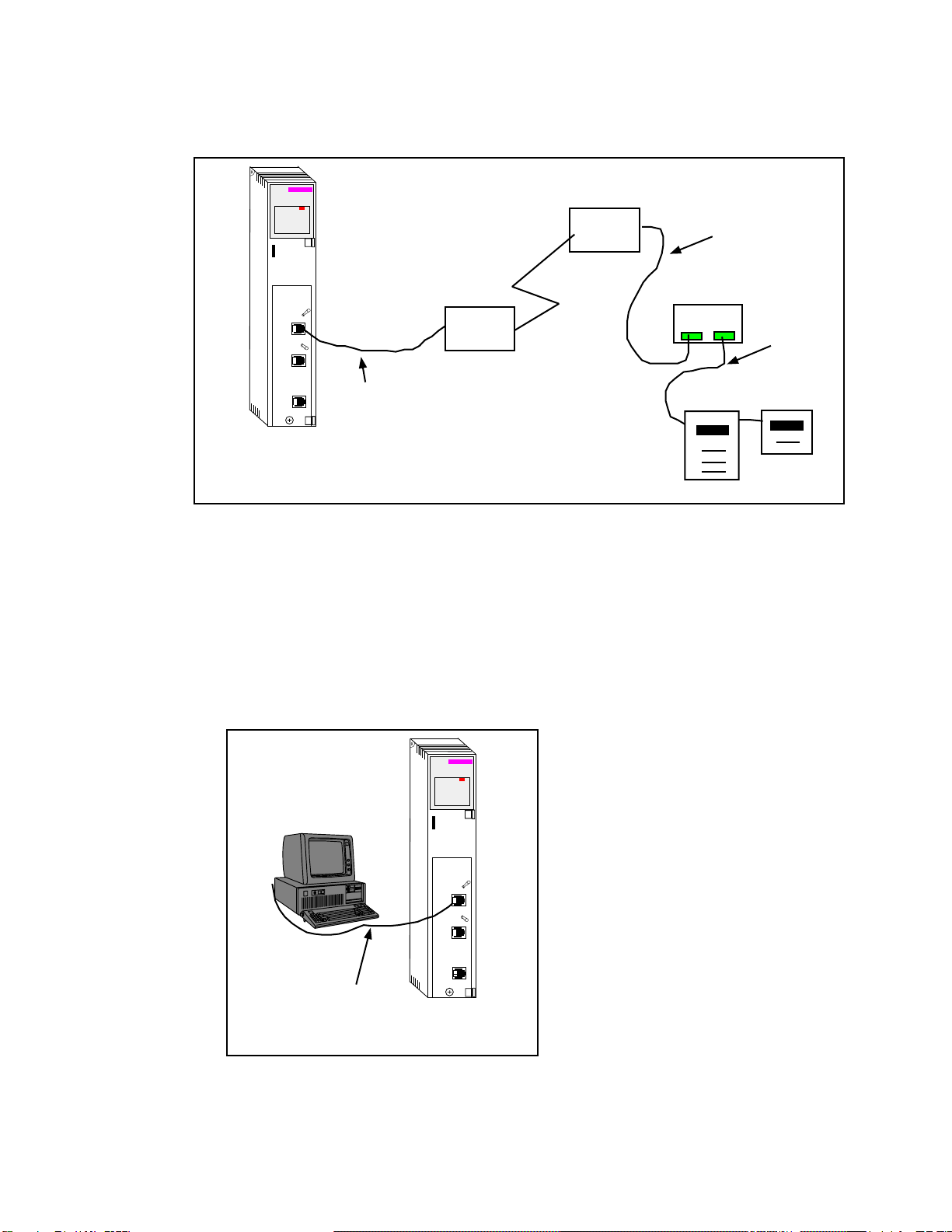
Figure 2-2 Typical system setup
Port 1 to the Personal Computer
A physical connection must be made from the personal computer to the QUCM in or-
der to configure the Ethernet parameters of the QUCM-OE. This link may be a serial
connection from a COM port on the personal computer to the RS-232 port on the
QUCM-OE. The Niobrara MM1 cable may be used for this connection. This cable
pinout is shown in Figure 2-4.
Figure 2-3 PC Connection to QUCM-LE serial port
MM12 Cable
140
QUCM
Niobrara
Active
Ready
Run
Col
Lnk
TXE
RXE
1
2
3
4
5
RN1
TX1
RX1
6
7
8
9
10
RN2
TX2
RX2
Fault
Modem
Modem MU12 Cable
MUCM
CM2000 PM620
4-wire
Cable
MM1 Cable
PC
140
QUCM
Niobrara
Active
Ready
Run
Col
Lnk
TXE
RXE
1
2
3
4
5
RN1
TX1
RX1
6
7
8
9
10
RN2
TX2
RX2
Fault

QUCM Modbus ASCII Modem Application Manual 2Installation 11
Figure 2-4 QUCM-SE to RS-232 PC Port (9-pin) (MM1 Cable)
Serial Connections to the MUCM-002
Port 1 to 25-pin DCE Modem
The RS-232 serial port of the MUCM is used to connect to the modem. The Niobrara
cable MM12 is used to connect to a standard 25-pin Modem.
NOTE: Do not use the MU4 cable for this application.
Figure 2-5 MUCM to RS-232 Modem DCE Port (25-pin) (MU12 Cable)
MUCM Port 1 to the Personal Computer
A physical connection must be made from the personal computer to the MUCM in or-
der to load the application. This link may be a serial connection from a COM port on
the personal computer to the RS-232 port on the MUCM. The Niobrara MU1 cable
may be used for this connection. This cable pinout is shown in Figure 2-6.
RJ45 DE9S (female)
32
43
55
64
76
7
8
Phoenix DE25P (male)
12
23
37
420
58
4
5

12 Installation 2QUCM Modbus ASCII Modem Application Manual
Figure 2-6 MUCM to RS-232 PC Port (9-pin) (MU1 Cable)
MUCM Port 2 to the Slaves
Standard Belden 8273 cable may be used to connect the MUCM to a 4-wire network
of slaves.
NOTE: 2-wire RS-485 networks may be formed by jumpering the TX+ to RX+ and
TX- to RX- on the MUCM.
Figure 2-7 MUCM to RS-232 PC Port (9-pin) (MU1 Cable)
Loading the Applications into the QUCM
The QUCM-OE must use the qucmtcpl.fwl or qucmtcpl.qcc firmware included in the
modem.zip file. This firmware is dated 28Oct2002 or later. There are two ways to
upgrade the firmware of the QUCM-LE: QLOAD and FWLOAD.
Phoenix DE9S (female)
12
23
35
44
56
7
8
Phoenix DE9S (female)
TX+ Green IN+
TX- White IN-
RX+ Red OUT+
RX- Black OUT-
Shield Shield Shield

QUCM Modbus ASCII Modem Application Manual 2Installation 13
Using ZAPREG32.EXE to set the IP Address
It is recommended to use the Ethernet capabilities of QLOAD to load the firmware,
APP!.QCC and APP2.QCC into the QUCM. Set up the IP parameters of the module
by the following method:
Figure 2-8 ZAPREG32 COM1:9600,E,8,1 255 -B
1 Move Switch 1 and Switch 2 to Halt.
2 Connect the PC to QUCM Port 1 with a MM1 cable.
3 From the command line enter
>zapreg32 com1:9600,e,8,1 255 -b
This will start zapreg32 in Modbus RTU mode to slave address 255. Use the ar-
row and Page Up/Down keys to move to register 46. The IP parameters are shown
below for a unit with the IP = 206.223.51.161 subnet Mask = 255.255.255.0, De-
fault Gate = 206.223.51.1, Modbus/TCP port number = 503:
Register DescriptionExample (decimal)
-------- ---------- ---------------------
46 IP MSByte 206
47 IP 223
48 IP 51
49 IP LSByte 161
50 SN Mask 255
51 SN Mask 255
52 SN Mask 255
53 SN Mask 0
54 Def. Gate 206
55 Def. Gate 223
56 Def. Gate 51
57 Def. Gate 1
58 (leave this alone)
59 (leave this alone)
60 (leave this alone)
61 (leave this alone)

14 Installation 2QUCM Modbus ASCII Modem Application Manual
62 (leave this alone)
63 Modbus Port 503 (this defaults to 502)
4 After entering the IP parameters, attempt to ping the module to verify the settings.
> ping 206.223.51.161
5 Verify a connection to the internal Modbus/TCP server with zapreg32.
> zapreg32 206.223.51.161:503 255
Should connect to the QUCM on port 503 with Destination index 255.
QLOAD QUCM Firmware Update
QLOAD is a convenient method for upgrading the firmware of a QUCM, especially if
the QUCM already has an IP Address. A direct serial connection to the module is not
required, the module does not need to be powered down, and the entire process may
be done remotely across the Ethernet.
1 Application 1 Switch must be in RUN.
2 Start QLOAD.EXE
3 Click on the Browse button and select the file qucmtcpl.qcc.
4 Select the Application 1 Radio Button.
5 Verify the following:
a. Status Register = 1.
b. Run Pointer Register = 33.
c. Auto Start is checked.
d. Erase Flash is checked.
e. Load File is checked.
f. The Modbus/TCP tab is selected.
(1) The IP Address of the QUCM is entered correctly.
(2) The TCP Port number is set to 503.
(3) The Modbus Drop is set to 255.
6 Press the Start Download button. QLOAD will open a progress window to show
the status of the download. Wait approximately 20 seconds for the upgrade to fin-
ish after the download is complete. The unit should be ready to received the new
versions of app1.qcc and app2.qcc.
FWLOAD QUCM Firmware Update.
If the QUCM has corrupt firmware or completely non-responsive then the old method
of using FWLOAD may be required.
Firmware upload is as follows:
1 Remove the module form the rack.
2 Move the RUN/LOAD switch on the back of the module to LOAD.

QUCM Modbus ASCII Modem Application Manual 2Installation 15
3 Replace the module in the rack and apply power.
4 Only the 3 light should be on. (The Link and RX E-net lights may be on if the
E-net port is connected and there is traffic.)
5 Connect the PC to QUCM Port 1 with a MM1 cable.. Make sure that Port 1 is set
to RS232 mode with the slide switch below the port.
6 From the command line enter
> fwload qucmtcp.fwl com1:
Be sure to have the colon after the PC’s com port name. The download will only
take a few minutes and will inform when finished.
7 Remove the module from the rack and change the switch back to RUN.
QLOAD APP1 and APP2
Figure 2-9 QLOAD of APP1
1 Application 1 and 2 Switches must be in RUN.
2 Start QLOAD.EXE
3 Click on the Browse button and select the file qucm_modem_app1.qcc.
4 Select the Application 1 Radio Button.
5 Verify the following:
a. Status Register = 1.
b. Run Pointer Register = 33.
c. Auto Start is checked.
d. Erase Flash is checked.
e. Load File is checked.
f. The Modbus/TCP tab is selected.
(1) The IP Address of the QUCM is entered correctly.
(2) The TCP Port number is set to 503.
16 Installation 2QUCM Modbus ASCII Modem Application Manual
(3) The Modbus Drop is set to 255.
6 Press the Start Download button. QLOAD will open a progress window to show
the status of the download.
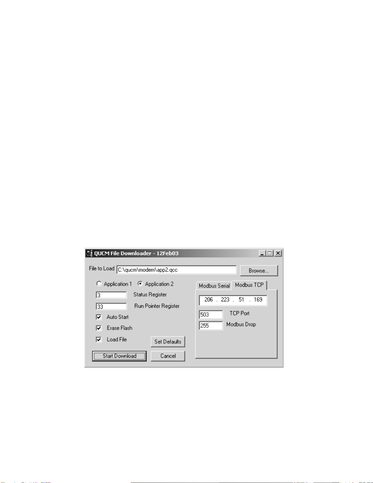
7 Click on the Browse button and select the file qucm_modem_app2.qcc.
8 Select the Application 2 Radio Button.
9 Verify the following:
a. Status Register = 3.
b. Run Pointer Register = 33.
c. Auto Start is checked.
d. Erase Flash is checked.
e. Load File is checked.
f. The Modbus/TCP tab is selected.
(1) The IP Address of the QUCM is entered correctly.
(2) The TCP Port number is set to 503.
(3) The Modbus Drop is set to 255.
10 Press the Start Download button. QLOAD will open a progress window to show
the status of the download.
After downloading both applications, the RN1 and RN2 lights should be on. Open a
web browser and point it to the IP Address of the QUCM for configuration.
Figure 2-10 QLOAD of APP2
Loading the Application into the MUCM
The MUCM-002 must use the mucm.fwl or mucm.qcc firmware included in the
modme.zip file. This firmware is dated 28Oct2002 or later. There are two ways to
upgrade the firmware of the MUCM-001: QLOAD and FWLOAD.

QUCM Modbus ASCII Modem Application Manual 2Installation 17
QLOAD MUCM Firmware Update
QLOAD is a convenient method for upgrading the firmware of a MUCM. A direct
serial connection to either port1 or port 2 on the MUCM is required.
1 Application 1 and 2 Switches must be in HALT
2 Start QLOAD.EXE
3 Click on the Browse button and select the file mucm.qcc.
4 Select the Application 1 Radio Button.
5 Verify the following:
a. Status Register = 1.
b. Run Pointer Register = 33.
c. Auto Start is checked.
d. Erase Flash is checked.
e. Load File is checked.
f. The Modbus Serial tab is selected.
(1) The COM port of the PC is selected in the pull-down.
(2) The baud rate is set to 9600.
(3) The Modbus Drop is set to 255
(4) The ASCII box is not checked.
(5) The 8 Bits button is checked.
(6) The Parity is set to EVEN.
6 Connect the PC to MUCM Port 1 with a MU1 cable..
7 Press the Start Download button. QLOAD will open a progress window to show
the status of the download.
8 Move switch 1 to RUN. Wait approximately 20 seconds for the upgrade to finish
after the download is complete. The unit should be ready to received the new ver-
sions of app1.qcc and app2.qcc.
FWLOAD MUCM Firmware Update.
If the QUCM has corrupt firmware or completely non-responsive then the old method
of using FWLOAD may be required.
Firmware upload is as follows:
1 Move the RUN/LOAD switch to LOAD.
2 Connect the PC to QUCM Port 1 with a MU1 cable..
3 From the command line enter
> fwload mucm.fwl com1:
Be sure to have the colon after the PC’s com port name. The download will only
take a few minutes and will inform when finished.
18 Installation 2QUCM Modbus ASCII Modem Application Manual
4 Remove the module from the rack and change the switch back to RUN.
QLOAD MUCMAPP1
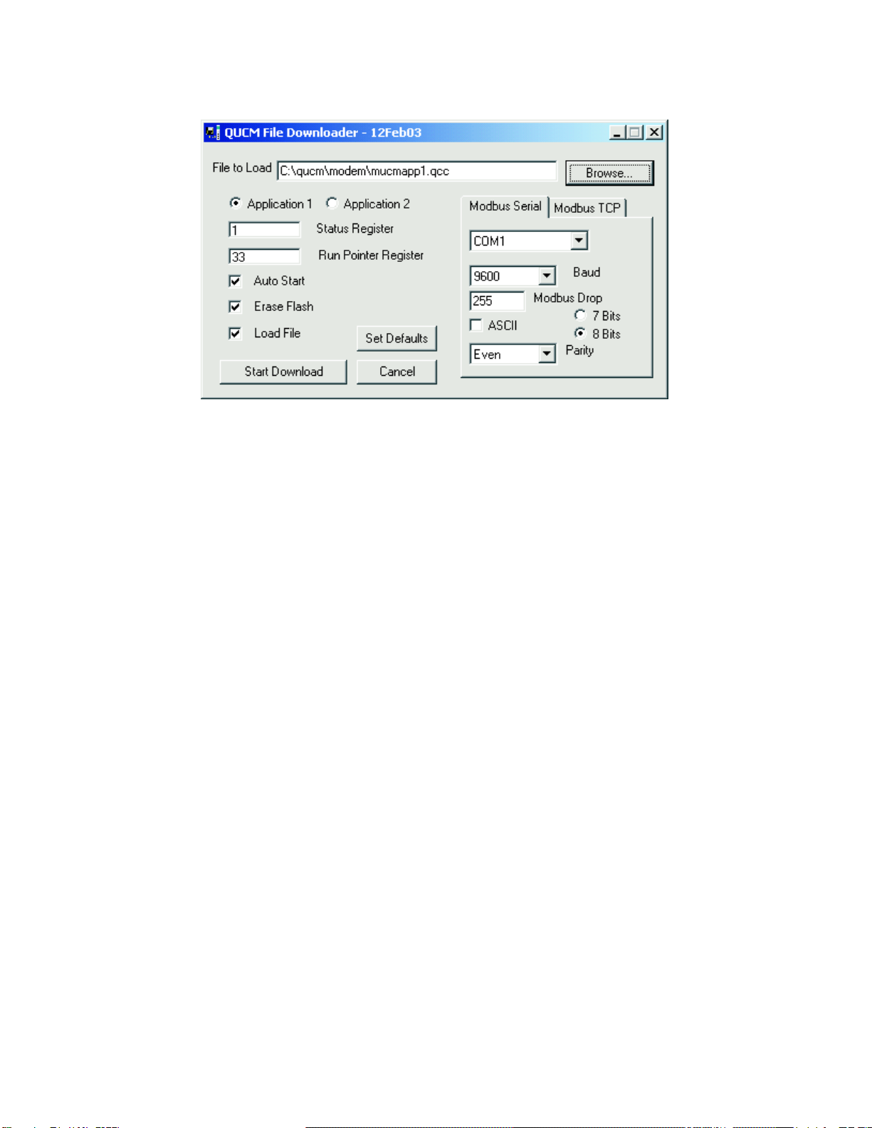
Figure 2-11 QLOAD of MUCMAPP1
1 Application 1 and 2 Switches must be in HALT.
2 Start QLOAD.EXE
3 Click on the Browse button and select the file mucm_modem_app1.qcc.
4 Select the Application 1 Radio Button.
5 Verify the following:
a. Status Register = 1.
b. Run Pointer Register = 33.
c. Auto Start is checked.
d. Erase Flash is checked.
e. Load File is checked.
f. The Modbus Serial tab is selected.
(1) The COM port of the PC is selected in the pull-down.
(2) The baud rate is set to 9600.
(3) The Modbus Drop is set to 255
(4) The ASCII box is not checked.
(5) The 8 Bits button is checked.
(6) The Parity is set to EVEN.
6 Connect the PC to MUCM Port 1 with a MU1 cable..
7 Press the Start Download button. QLOAD will open a progress window to show
the status of the download.

QUCM Modbus ASCII Modem Application Manual 2Installation 19
8 Select the Application 2 Radio Button.
9 Verify the following:
a. Status Register = 3.
b. Run Pointer Register = 33.
c. Auto Start is NOT checked.
d. Erase Flash is checked.
e. Load File is NOT checked.
f. The Modbus Serial tab is selected.
(1) The COM port of the PC is selected in the pull-down.
(2) The baud rate is set to 9600.
(3) The Modbus Drop is set to 255
(4) The ASCII box is not checked.
(5) The 8 Bits button is checked.
(6) The Parity is set to EVEN.
10 Press the Start Download button. QLOAD will open a progress window to show
the status of the download. This step is to simply erase the FLASH for applica-
tion 2 to make sure that a previous program is not accidentally running.
After downloading both applications, move the Application Switch 1 to RUN. The
RN1 light should be on.

This manual suits for next models
2
Table of contents
Popular Modem manuals by other brands


IBM
IBM 715 P/N - 13H6715 user manual

VisionTek
VisionTek 81GC Instructions for use, installation & servicing

Devolo
Devolo Magic 2 WiFi next Installation

ActionTec
ActionTec 56K Internal PC Modem user manual

D-Link
D-Link DWR-910M Quick installation guide

Belkin
Belkin ADSL Modem with Wireless-G Router F5D7632UK4 user manual