Nippon Gases MICROTIG DC 162 PULSE Quick guide
MANUAL
MICROTIG DC 162PULSE
2719135
MICROTIG DC 202 PULSE
2719161
OPERATING AND SAFETY INSTRUCTIONS
Note: It is essential to read these operating instructions before starting up
the equipment. .
Otherwise, it could be dangerous.
The machines may only be used by personnel familiar with the relevant
safety regulations. The machines bear the mark of conformity and
therefore comply with the following regulations:
-EC Low Voltage Directive (73/23/EEC)
-EC EMC Directive (89/336/EEC)
(CE marking is only required in Member States) In accordance with
IEC60974, EN60974, VDE0544, the machines may be used in environments
with a high electrical risk.
Z
Rev.:
0 03 /2020

2
ES
PT
MICROTIG DC 162 / 202 PULSE
GENERAL TABLE OF CONTENTS
INSTRUCCIONES DE MANEJO Y SEGURIDAD (ESPAÑOL) ................................................3
INSTRUÇÕES DE USO E SEGURANÇA (PORTUGUES) ....................................................23

3
MICROTIG DC 162 / 202 PULSE
ES
PT
EU- DECLARACIÓN DE CONFORMIDAD
EU- CERTIFICADO DE CALIDAD
Nippon Gases España S.L.U. C/Orense, 11, 28020 Madrid
Producto Modelo Código
INVERTER PARA SOLDADURA MICROTIG DC 162 PULSE
MICROTIG DC 202 PULSE
2719135
2719161
NORMATIVA
NIPPON GASES ESPAÑA S.L.U., como empresa fabricante y distribuidora de máquinas, aparatos y artículos de
soldadura y corte, DECLARA que el producto suministrado cumple con los requisitos descritos en las Directivas y
Normas Comunitarias indicadas a continuación.
–Compatibilidad de Electromagnetismo (EMC): 2004/108/EC
–Bajo voltaje (LVD): 2006/95/EC
Pruebas EMC SCC(06)-206-10-EMC of 2008-10-16
Estándares de las pruebas: EN 60974-10:2007
Pruebas LVD 20081250 of 2008-09-24
Estándares de las pruebas: EN 60974-1:2005
INDICACIONES
La presente Declaración de Conformidad implica que:
–El equipo es seguro
–Es conforme para el uso al que está destinado
–Existen controles de fabricación que garantizan el mantenimiento de la calidad del producto.
–
Los componentes del equipo son apropiados para el uso al que están destinados y cumplen con las
correspondientes normas y directivas de aplicación.
Esta declaración no tendrá validez en el caso de cambios no autorizados, reparaciones inadecuadas o
modificaciones que no hayan sido expresamente aprobadas por NIPPON GASES ESPAÑA, S.L.U
Jefe de Producto
Product Manager
Madrid, 4 de noviembre, 2019
José Rivas

4
ES
PT
MICROTIG DC 162 / 202 PULSE
ÍNDICE ESPAÑOL
1. WARRANTY..........................................................................................................................5
2. SAFETY........................................................................................................................6
2.1 Emission reduction methods .......................................................................7
2.2. Electric safety.....................................................................................................8
2.3. Individual protection...................................................................................................8
3. TIG WELDING (Tungsten Inert Gas) ............................................................................. 11
4. MMA WELDING (electrodo revestido) ........................................................................ 12
5. CONTROL PANEL........................................................................................................ 13
6. CHARACTERISTICS .......................................................................................................... 14
7. INSTALLATION .................................................................................................................. 14
7.1. Connection to the power supply ............................................................................. 14
7.2 Connection........................................................................................................ 14
8. FUNCTIONS ...................................................................................................................... 15
8.1. MMA process welding(electrodo revestido) .......................................................... 15
8.2. TIG welding............................................................................................................ 16
8.3. SPOT welding mode ............................................................................................17
8.4. JOBS - Welding programmes ............................................................................... 18
9. ERROR DESCRIPTION............................................................................................. 18
10. WIRING DIAGRAM...................................................................................................... 19
11. LIST OF PARTS ............................................................................................................ 20
12. MAINTENANCE............................................................................................................ 22
12.1. Breakdown repairs ..............................................................................................22

5
MICROTIG DC 162 / 202 PULSE
ES
PT
1. WARRANTY
The purchase invoice guarantees your warranty. The number of this invoice must be indicated on
each warranty claim.
All materials are guaranteed for 12 months from the date of invoice, unless otherwise specified.
Defects or deterioration caused by natural wear and tear or by an external accident (incorrect
assembly, faulty maintenance, abnormal use...) or by a modification of the product not accepted in
writing by the seller, are excluded from the guarantee.
The guarantee only covers the free replacement of recognised defective spare parts (transport not
included).
(transport not included).
The workmanship carried out by the distributor is entirely at your expense. However, if you wish, the
labour may be carried out free of charge by NIPPON GASES S.L.U., in its establishments, provided that
the return transport is paid for by the distributor.
NIPPON GASES S.L.U. reserves the right to modify its equipment without prior notice. Illustrations,
descriptions and characteristics are not contractual and do not engage the responsibility of the
manufacturer.
Nippon Gases S.L.U. reserves the right to modify its equipment without prior
notice. Illustrations, descriptions and characteristics are not contractual and do
not engage the responsibility of the manufacturer.

6
ES
PT
MICROTIG DC 162 / 202 PULSE
2. SAFETY
This machine, in its design, component specification and production, is in accordance
with the regulations in force [EU directives, European (EN) and international (IEC)
standards. The European Directives "Electromagnetic Compatibility", "Low Voltage" and
"RoHS" as well as the IEC / EN 60974-1 and IEC / EN 60974-10 standards are applicable.
Electric shocks can be fatal.
-This machine must be connected to earthed sockets. Do not touch the live parts
of the machine.
-Before any intervention, disconnect the machine from the mains. Only qualified
personnel should work on these machines.
-Always check the condition of the power cable.
It is essential to protect the eyes from the radiation of the electric arc. Use a welding
shield with a suitable protective filter.
Use localised extraction. Smoke and fumes can damage the lungs and cause poisoning.
Risk of fire or explosion.
-Remove all explosive or flammable products from the welding area;
-Check that there is a sufficient number of fire extinguishers in the vicinity of the
welding area;
-Check that the sparks projected cannot cause a fire, remembering that these
sparks can reignite several hours after the end of welding.
Hot parts can cause burns. Workpiece, spatter and droplets are hot. Wear gloves,
aprons, safety shoes and other personal safety equipment.
Electromagnetic fields generated by welding machines may cause interference to other
devices. They may affect cardiac pacemakers.
Gas bottles can explode (MIG or TIG welding). It is essential to comply with all safety
regulations regarding gases.
Electromagnetic compatibility
If electromagnetic disturbances occur, it is the responsibility of the user to remedy the problem with
the manufacturer's technical support. In some cases, corrective action may be reduced to simply
grounding the welding circuit (see note below). In the opposite case, it may be necessary to build an
electromagnetic shield around the source and add input filters to this measure. In any case,
electromagnetic disturbances should be reduced until they do not disturb nearby welding equipment
or persons. The following situations should be taken into account:
-Power cables, control cables, display and telephone cables close to the welding equipment.
-Radio and television transmitters and receivers.

7
MICROTIG DC 162 / 202 PULSE
ES
PT
- Computers and other control equipment.
- Safety-critical equipment, in particular the monitoring of industrial equipment.
-Health of the people around, in particular those wearing cardiac stimulants and hearing aids.
-Equipment used for calibration.
-Immunity of other surrounding equipment. The user must ensure that these materials are
compatible. This may require additional protective measures.
-Time at which welding materials and other equipment operate.
2.1. Methods to reduce emissions
Power supply
The welding equipment must be connected to the mains according to the manufacturer's instructions.
Should interference occur, it may be necessary to take additional precautions such as filtering the
power supply. It is necessary to take into account the shielding of the power cables of welding
equipment permanently installed in metallic conduits or equivalent. Shielding must be carried out in
compliance with electrical continuity. The welding source must be connected in such a way that there
is always a good electrical contact.
Welding Cables
Welding cables should be as short as possible and in good serviceable condition (no splices), on or near
the ground.
Equipotential bonding
The links between all metallic components in and adjacent to the welding installation must be taken
into account. However, metallic components connected to the part being worked on increase the risk
of electric shock if the user touches the metallic components and the electrode at the same time. The
user must be isolated from all connected metallic components.
Earth connection
When the part to be welded is not earthed for electrical safety reasons or because of its size or position
(e.g. ship hull, steel mill), a connection of the part to earth may reduce emissions in some cases. Care
must however be taken to ensure that this connection does not increase the risk of injury to the user or
damage other electrical equipment. When necessary, the grounding of the part must be made by a
direct connection, but in some countries where this is not authorised, the connection must be made by
a capacitance resistor and according to national regulations.
Shielding and protection
Selective shielding and protection of other cables and materials in the surrounding area can limit
interference problems. Shielding of the entire welding installation may be considered for special
applications.

8
ES
PT
MICROTIG DC 162 / 202 PULSE
2.2. Electric safety
Connection to the power supply
Before connecting your appliance, check that:
-The electrical meter, the overcurrent protection device and the electrical installation are
compatible with the maximum power and supply voltage of your welding equipment (indicated
on the nameplate).
-The single-phase or three-phase earthed connection must be made on a basis appropriate to
the maximum current of the welding equipment.
-If the cable is connected to a fixed post, the earth, if provided, shall never be cut off by the
electric shock protection device.
-The welding power source switch, if provided, shall indicate "OFF".
Job position
The application of arc welding implies strict compliance with the safety conditions regarding electric
current (decree of 14.12.1988). It is necessary to ensure that no metallic part accessible to welders can
come into direct or indirect contact with a conductor of the power supply network. If there is any doubt
about this serious risk, a conductor of this metallic part shall be connected to earth with an electrical
cross-section at least equivalent to that of the largest phase conductor.
It is also necessary to ensure that a conductor connects any metallic part which the welder could
touch on an uninsulated part of the body (head, ungloved hand, bare arm, etc.) to earth of an electrical
cross-section at least equivalent to that of the largest power cable of the earth clamp or welding
torch. If several metal grounds are used, they shall be connected at one point, earthed under the same
conditions.
Welding and arc cutting shall be prohibited, except in very special cases in which stringent measures
shall be applied, in narrow conductive enclosures in which welding apparatus must be left outside.
Very serious safety measures shall be compulsory a priori for welding in poorly ventilated or damp
enclosures.
Risk of fire or explosion
Welding may involve risks of fire or explosion. Some precautions must be observed:
-Remove all explosive or flammable products from the welding area;
-Check that there is a sufficient number of fire extinguishers in the vicinity of the welding area;
-Check that the sparks projected cannot cause a fire, remembering that these sparks can
reignite several hours after the end of welding.
2.3. Individual protection
Risks of external injury
Electric arcs produce very bright infrared light and ultraviolet rays. These rays will damage your eyes
and burn your skin if not properly protected.
-The welder must be equipped and protected according to the difficulties of the work.
-They must be covered in such a way that no part of the welder's body can come into contact with
metal parts of the welding equipment, and also those which could come into contact with the
voltage of the mains supply.

9
MICROTIG DC 162 / 202 PULSE
ES
PT
-The welder must always wear individual insulating protection.
The welder's protection systems shall be as follows: gloves, aprons, safety shoes, etc. These offer
the additional advantage of protecting against burns caused by spatter and slag. Users must ensure
that these protective systems are in good condition and renew them if they deteriorate.
-It is essential to protect the eyes against arc flash (glare from the arc in visible light and infrared
and ultraviolet radiation).
-Hair and face against projections.
The welding shield, with or without helmet, is always provided with a protective filter specified in
relation to the current intensity of the welding arc (NS Standards S 77-104/A 88-221/A 88-222). The
coloured filter can be protected from shocks and projections by transparent glass.
The screen used must be used with a protective filter. It must be replaced by the same references
(opacity level number). See the table below for the level of protection recommended for the welding
method.
Persons in the vicinity of the welder must be protected by the interposition of UV protection screens
and, if necessary, by a welding screen provided with a suitable protective filter (NF S 77-104- por. A 1.5).
WELDING PROCESS NTENSITY OF CURRENT AMP.
0,5 2,5 10 20 40 80 125 175 225 275 350 450
1
5
15
30
60
100
150
200
250
300
400
500
Electrodes 9 10 11 12 13 14
MIG on metal 10 11 12 13 14
MIG on alloys 10 11 12 13 14 15
TIG on all metals 9 10 11 12 13 14
MAG 10 11 12 13 14 15
Arc/Air 10 11 12 13 14 15
Plasma Cutting 9 10 11 12 13
Depending on the conditions of use, it should be set to the nearest number.
The term "metal" means steels, copper and copper alloys.
The shaded area represents applications where the welding process is not normally used.
Risks of internal injuries
Safety against fumes and vapours, noxious and toxic gases
-Arc welding operations with electrodes must be carried out in suitably ventilated areas.
-Welding fumes emitted in workshops must be collected as they are produced, as close as
possible to their production and discharged directly to the outside. Fume extractors must be
installed for this purpose.
-Chlorinated solvents and their vapours, even at a distance, if affected by arc radiation, are
transformed into toxic gases.

10
ES
PT
MICROTIG DC 162 / 202 PULSE
Safety in the use of gases (TIG or MIG inert gas welding)
Compressed gas cylinders
Comply with the safety standards indicated by the gas supplier and in particular:
-Avoid knocks when holding the bottles.
-Avoid heating above 50 °C.
Pressure reducer
Make sure that the release screw is loosened before the connection is made on the cylinder.
Check the tightness of the connection before opening the cylinder valve. Open the bottle tap slowly.
In the event of a leak, never loosen a connection under pressure; close the bottle tap first.
Always use flexible hoses in good condition.

11
MICROTIG DC 162 / 202 PULSE
ES
PT
3. TIG WELDING (Tungsten Inert Gas)
It is an electric arc welding process under gaseous protection, using a torch with an infusible tungsten
electrode and can be performed with or without filler metal, in an inert gas atmosphere such as argon
and its mixtures.
The melting temperature of the tungsten electrode is 3400ºC higher than the metals to be welded so it
does not melt or release contaminating welding atoms.
Through this process you can weld with a very stable electric arc without spatter and slag which
guarantees a high mechanical strength of the welded joints.
TIG welding replaces oxyacetylene welding with advantages especially in the welding of mild steels and
stainless steel in direct current (DC) or aluminium and its alloys in alternating current (AC).
In specific cases, it can also be advantageous in connection with mainly MMA welding (fusible
electrode) or MIG welding that does not require the addition of metal or thin sheets in which the wires
are not visible.
Composición química de los electrodos
Código
Composición
Tipo
Color
Soldadura
WP
Tungsteno puro
W
Verde
AC – Aluminio, Magnesio
WT4
0,35-0,55% torio
Th
Azul
DC
Acero carbono, Acero inox,
Titanio
Cobre
WT10
0,80-1,20% torio
Amarillo
WT20
1,7-2,3% torio
Rojo
WT30
2,7-3,3% torio
Violeta
WT40
3,8-4,3% torio
Naranja
WZ3
0,15-0,50% zirconio
Zr
Marrón
Acero inox, Níquel,
Metales no ferrosos
WZ8
0,70-0,10% zirconio
Blanco
WL10
1,0-1,2% lantano
La
Negro
Todas aplicaciones TIG
WC20
1,9-2,3% cerio
Ce
Gris
Todas aplicaciones TIG
Tabla de diámetros y corrientes aplicables a los electrodos
∅
eléctrodo
(mm)
Amp. DC
Amp. AC
Negativo (-)
Positivo (+)
1,6 mm
40-130 A
10-20 A
45-90 A
2,0 mm
75-180 A
15-25 A
65-125 A
2,5 mm
130-230 A
17-30 A
80-140 A
3,2 mm
160-310 A
20-35 A
150-190 A
4,0 mm
275-450 A
35-50 A
180-260 A
5,0 mm
400-625 A
50-70 A
240-350 A

12
ES
PT
MICROTIG DC 162 / 202 PULSE
Shielding gases: Gases used in TIG welding contribute to:
-To involve the electric arc in an ionisable atmosphere.
-Avoid contamination of the weld by oxygen in the atmosphere.
-To cool the electrode.
Argon(Ar)
The most common gas used with a purity grade of 99.9%.
Helium (He)
Pure helium is used for copper welding mixed with argon in percentages varying between 10% and
75%.
Hydrogen (H)
It is an inert gas at room temperature and is used especially in copper soldering. It is not
recommended for soldering in enclosed spaces because it combines with oxygen to create an
unbreathable atmosphere.
4. MMA WELDING (coated electrode)
To establish a welding arc, a potential difference is induced between the electrode and the workpiece.
potential difference between the electrode and the workpiece.
The air between them is ionised and becomes conductive, so that the circuit is closed and creates the
electric arc. The heat of the arc partially melts the base material which is deposited creating a weld
pool. Arc welding is still very common due to the low cost of the equipment and consumables used in
this process.
An electric arc is formed between the electrode and the metal to be welded by means of an electric
current. The temperatures reached cause it to melt and deposit in the welded joint. Metal core
electrodes made of steel or other alloys are coated with a fluxing material which creates a protective
atmosphere that prevents oxidation of the molten metal and facilitates the welding operation.
In DC power sources (rectifiers) the polarity of the electric current affects the mode of metal transfer.
Typically, the electrode is connected to the positive (+) pole, although in welding very thin materials, it
may be connected to the negative (-) pole.
The most favourable welding position is horizontal, while welding can be carried out in any position.
Porta-electrodos
Electrodo revestido
Zona de soldadura
Transferencia
de metal
Atmosfera de
protección de arco
Pieza a soldar Pinza de masa

13
MICROTIG DC 162 / 202 PULSE
ES
PT
Tabla de parámetros de soldadura MMA:
Diámetro electrodo
Intensidad de corriente
Espesor de chapa
∅2,5 mm
40 – 125 A
> 2 mm
∅3,2 mm
105 – 250 A
> 3 mm
∅4,0 mm
75 – 185 A
> 6 mm
∅5,0 mm
140 – 305 A
> 9 mm
∅6,0 mm
210 – 430 A
> 9 mm
∅8,0 mm
275 – 450 A
> 9 mm
5. CONTROL PANEL
1
Welding mode selector: TIG HF (TIG welding with high frequency ignition), LIFTIG (TIG welding
with contact ignition), MMA welding, PULSE (when on with another mode also on, indicates
pulsed welding of the respective welding mode).
2
Indicator for machine switched on and under voltage
3
Overheat indicator - switches the machine off in case of overheating due to overloading
4
VRD - MMA VRD - No-load voltage reduction for use in environments with increased risk of
electric shocks
5
Selector 2T/4T and SPOT
6 Welding current and voltage display
7
Welding programs / welding current / welding voltage key - when pressed, allows selection
of welding programs and displays welding current or welding voltage on the digital display.
8
Parameter selection and setting - Allows selection of parameters by pressing / setting
of parameters by turning
9
Welding parameters - see description of these parameters in this instruction
manual.

14
ES
PT
MICROTIG DC 162 / 202 PULSE
6. CHARACTERISTICS
162
202
Single-phase power supply V** 1 x 230 V (-+10%) 1 x 230 V (-+10%)
Frequency Hz 50/60 50/60
Maximum primary current (MMA) A 34 43
Maximum primary current (TIG) A 24 30
Maximum power absorbed (MMA) KVA 7,8 9,9
Maximum absorbed power (TIG) KVA 5,5 6,9
SECONDARY
No-load voltage V 74 80
Welding current regulation A 10 - 160 10 - 200
40 % welding current A 160 200
60 % welding current A 135 160
100 % welding current A 105 125
Protection class IP 21S IP 21S
Insulation class H H
Standards IEC / EN 60974-1 IEC / EN 60974-1
Weight Kg 7 7,6
Dimensions cm 15 x 24 x 39 15 x 24 x 39
7. INSTALLATION
7.1. Connection to the power supply
The equipment must be supplied with 230V - 50 Hz/60 Hz single-phase + earth.
The power supply must be fitted with a device (fuse or circuit breaker) corresponding to the I1eff value
indicated on the nameplate of the equipment.
The installation of a differential protection device is not compulsory except for the safety of the users.
7.2. Connection
For the protection of the users, the equipment must be correctly connected to the earthing installation
(INTERNATIONAL SAFETY RULES).
It is essential to establish a good earth connection via the green/yellow conductor of the power cable in
order to avoid discharges due to accidental contact with live parts in contact with earth. If the earth
connection is not made, there is a risk of electric shock to the machine casing.
Avoid placing the device in rooms with high dust concentration, humidity or excessive ambient
temperatures.
15
MICROTIG DC 162 / 202 PULSE
ES
PT
8. FUNCTIONS
8.1. MMA process welding (stick welding)
-Make the connections to the mains and earth as indicated in the "Installation" chapter. Connect
the earth cable and electrode holder to the + (positive) and - (negative) quick connectors
according to the polarity of the electrode used and in accordance with the manufacturer's
instructions.
-Switch on the equipment with the ON/OFF switch located on the rear panel of the machine.
-The machine connected and under voltage indicator lights up, indicating that the machine is
under voltage.
-Select MMA (stick welding) or MMA PULSED welding (both indicators are lit).
-Set the current value (Fig.1 - 2), according to the following table:
Electrode diameter
(mm)
Ø2,0 Ø2,5 Ø3,2 Ø4,0 Ø5,0 Ø6,0
Welding current range
(A)
50 - 70 60 - 100 80 - 150 130 - 200 150 - 260 200 - 360
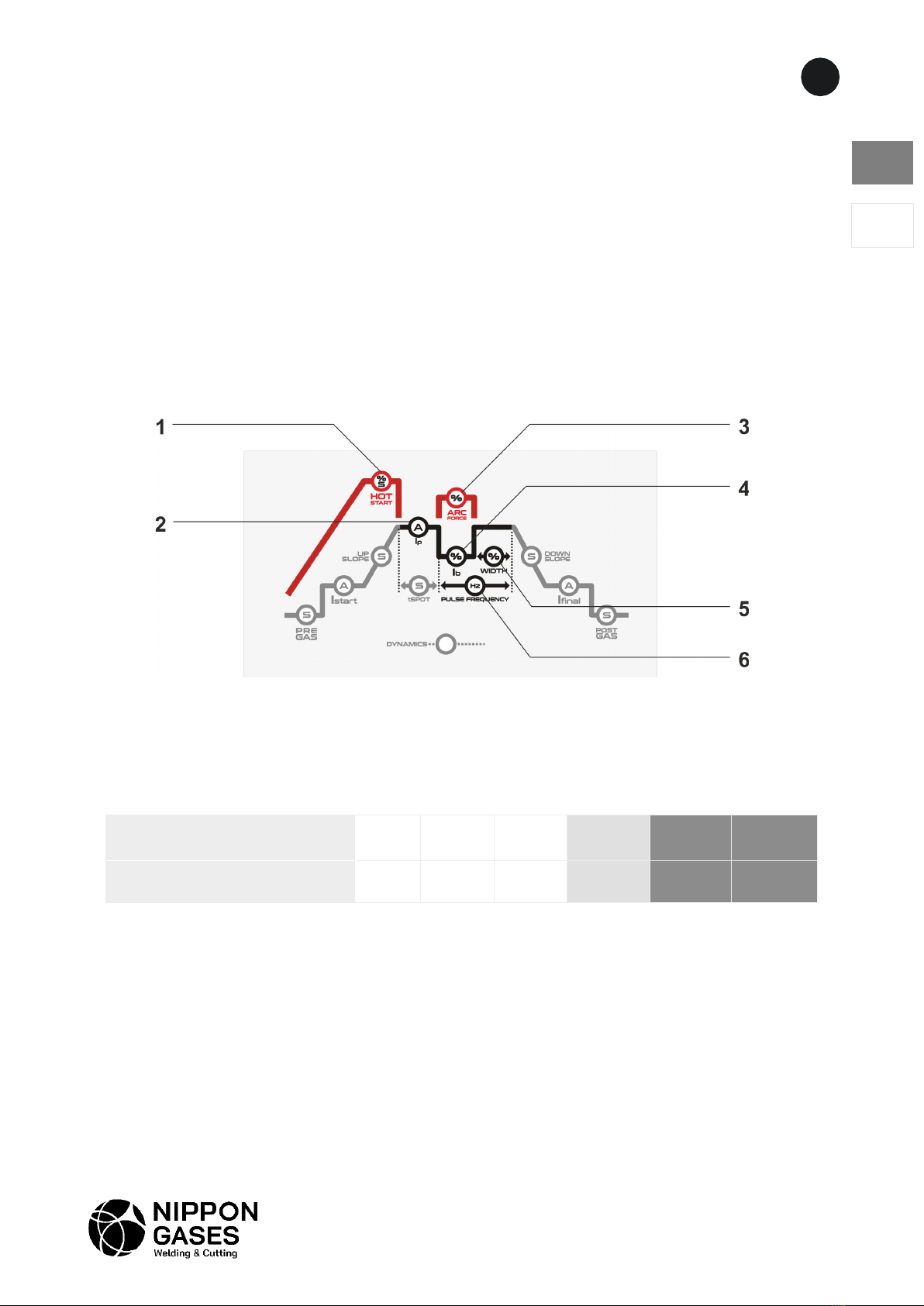
-Hot Start (Fig.1 - 1) - To improve arc starting, adjust the hot start percentage in relation to the
main current and/or time (seconds).
-Arc Force (Fig.1 - 3) - To prevent the electrode from being pulled into the workpiece during
welding, adjust the arc force percentage in relation to the main current.
Pulsed MMA welding - the welding current oscillates between a high and low value, for less thermal
delivery on thinner sheets and more control of the arc in the most demanding positions (vertical up).
-Ib (Fig.1 - 4) - set the base current as a percentage of the main current.
-WIDTH (Fig.1 - 5) - adjust the width of the peak (main) current from 10% to 90%.
-PULSE FREQUENCY (Fig. 1 - 6) - set the pulse frequency in Hertz.
-Start welding.
Fig. 1 – Parámetros MMA
16
ES
PT
MICROTIG DC 162 / 202 PULSE
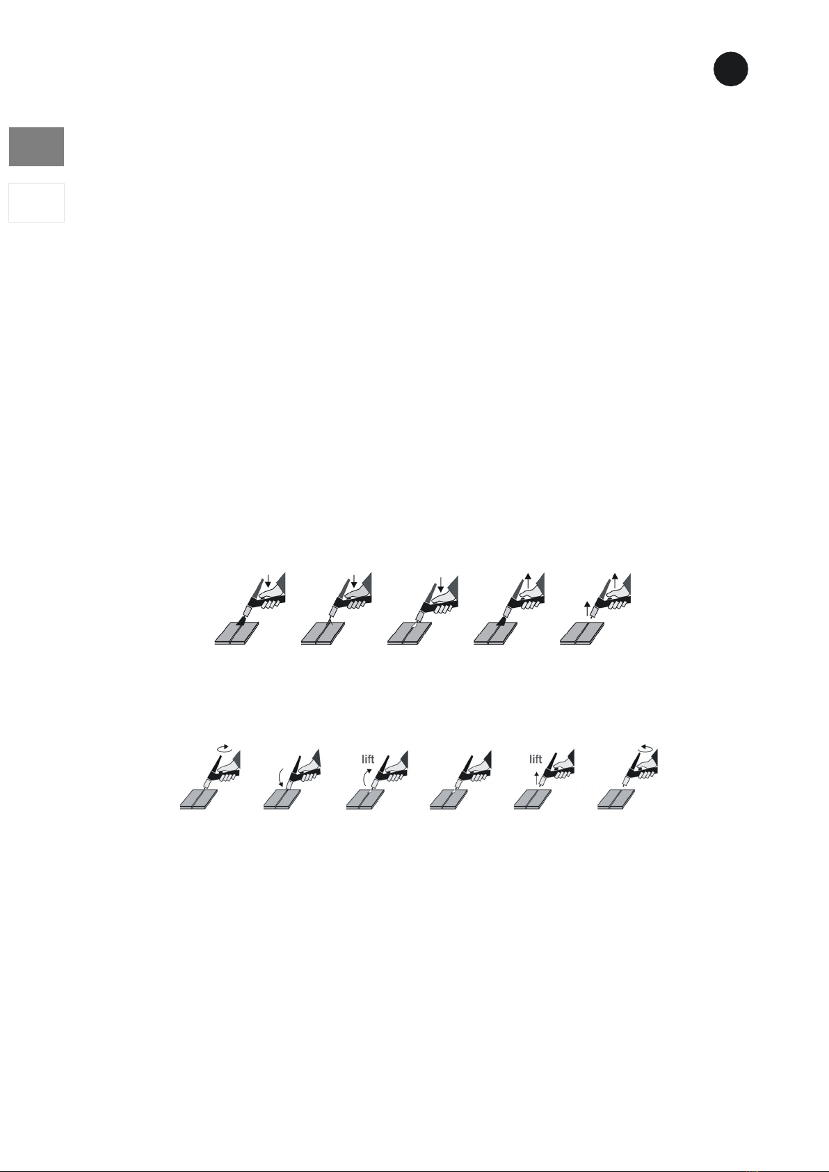
1-abrir gas 2-contact 3-cebado 4-soldadura 5-parar 6-cerrar gas
1-pré-gas 2-cebado HF 3-soldadura 4-post-gas 5-parar
8.2. TIG welding
- Make the mains and earth connections as described in the chapter "Installation".
- Connect the earth clamp cable to the positive socket by rolling it firmly to the right until a
perfect contact is ensured.
- Connect the power cable of the TIG torch to the negative socket by turning it firmly clockwise
until a perfect contact is ensured.
- Connect the gas hose of the TIG torch to the gas connection.
- Connect the torch control cable plug to the front panel connection.
- Connect the gas tube of the torch to the gas inlet on the rear panel and to the gas tube flow
meter. Check the gas content in the tube and, if necessary, change it.
- Regulate the gas flow through the pressure regulator of the flow meter 6 l/min and 12 l/min
depending on the current value.
- Apply the appropriate tungsten electrode to the TIG torch. The electrode must be sharpened
according to the selected welding mode - TIG DC sharpened on the tip.
- Switch on the machine by turning the main switch, located on the rear panel, to the ON position.
- The machine on and over voltage indicator lights up, indicating that the machine is over voltage.
- Select either TIG HF* (TIG welding with high frequency ignition) or LIFTIG** (TIG welding with
contact ignition). In both modes, there is a pulsed welding mode function - PULSED (both
indicators are lit respectively).
* TIG HF:
** LIFTIG:
This process is used in premises where the emission of high frequency waves may affect the operation
of sensitive electronic devices such as computers, hospital equipment, cardiac pacemakers, etc.
-Select 2T* (2-stroke) / 4T** (4-stroke) mode.
* 2T - Gas starts flowing according to the set PREGAS time when the torch trigger is pressed, and the
arc is established. The current rises according to the UPSLOPE time and the current IStart value for
the set Ip value. When the torch trigger is released, the current decreases according to the IFinal
current value. After the set DOWNSLOPE time, the arc is switched off and the POST GAS time starts.
17
MICROTIG DC 162 / 202 PULSE
ES
PT
** 4T - The gas starts to flow according to the set PREGAS time when the torch trigger is pressed.
When the torch trigger is released, the arc is automatically established. The current rises according to
the UPSLOPE time and the current IStart value for the set Ip value. When the torch trigger is pressed
and released, the current decreases according to the IFinal current value. After the set DOWNSLOPE
time, the arc is switched off and the POST GAS time starts.
-Adjust the welding parameters of the TIG cycle.
** DYNAMICS - Set ON or OFF by turning the parameter setting knob at the end of the TIG cycle
parameters to the left (OFF) or to the right (ON). Not available in PULSED mode.
-Start welding.
8.3. SPOT welding mode
-Follow the instructions for TIG mode but when selecting the 2T/4T/SPOT button, select SPOT.
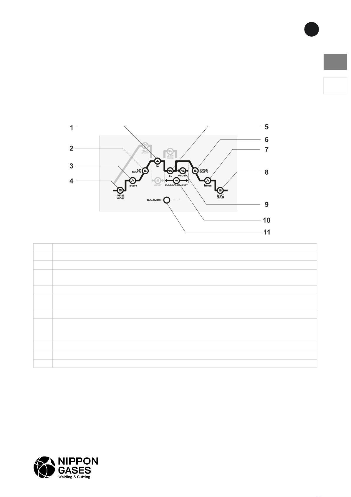
1 Welding current or, in pulsed mode, peak current
2
Up slope time in seconds from IStart to welding current (Ip)
3
IStart - Initial current in Amps
4
Pre-gas time in seconds - interval between gas flow and arc ignition. Allows welding to be
started with a shielding gas atmosphere.
5 Base current indicator (in pulsed mode).
6
Down slope time from the main stream to the final stream for crater treatment.
7
IFinal - Final current for crater treatment.
8
Post-gas time - interval after arc extinction to maintain the shielding gas at the end of
welding. Prevents the weld pool and tungsten electrode from oxidation.
9
Width - Length gives peak current from 10% to 90%.
10
Pulse frequency - set pulse frequency in Hertz
11
DYNAMICS - with arc length compensation for beginner welders*.

18
ES
PT
MICROTIG DC 162 / 202 PULSE
-Set the spot time (tSPOT) from 0.1 to 20 seconds.
-Start spot welding by pressing the torch trigger and continuing to press until the end of the set
TIG cycle.
8.4. JOBS - Welding programmes
This machine has 20 memories for storing and repeating your welding programmes.
- To save a welding programme, set the parameters and press the button (Fig.1 - 10) until the LED P
lights up. Then press the parameter selection/setting knob for 2 seconds until the digital display
shows P1. Then turn the parameter selection/setting knob to the desired programme number.
Finally, press the parameter selection/setting knob until the digital display shows MEM.
- To access a programme: Press the key (Fig. 1 - 10) until LED P lights up. Then turn the parameter
selection/setting knob to the desired programme number. Wait 2 seconds and your programme is
available.
- When you change the parameter values, the machine automatically switches to P0.
- After switching off the machine, your programmes will still be stored.
9. ERROR DESCRIPTION
Er1 - Overheating - Switches the machine off in case of overheating due to overloading

19
MICROTIG DC 162 / 202 PULSE
ES
PT
10.WIRING DIAGRAM

20
ES
PT
MICROTIG DC 162 / 202 PULSE
11. LIST OF PARTS
This manual suits for next models
3
Table of contents
Languages:


