McAnax MIG-160E User manual

Inverter DC MIG Welder Manual www.gentt.ie
Operator’s Manual
Inverter DC MIG Welder
(MIG-200)
With LED Display
Warning!
This machine should be operated and maintained by competent or
professionals. Repairs should only be carried out after reading the manual

Inverter DC MIG Welder Manual www.gentt.ie
CONTENTS
Safety……………………..………………..……………………............................... 2
General Description………..………………..……………………........................... 3
Main Parameter………..………………..………………..……............................... 5
Structure of Welder……..………………..….………………….............................. 6
Installation…………..…...……………..……………………................................... 9
Welder Settings Quick Reference Chart.....………………..………………........... 14
Range of Welding Current and Voltage in CO2 Welding………....………........... 19
Welding parameters table………..............................……..………….……........... 19
Caution…………..…...……………..……………………........................................ 22
Maintenance………..…...…………….....………………........................................ 23
Daily Checks………..…...……………………………............................................. 24
Connection Diagram of the Machine…………..………........................................ 22
Exploded Diagram......…..………………..….………………….............................. 6
Plug Installation..........…..………………..….………………….............................. 6
1

Inverter DC MIG Welder Manual www.gentt.ie
SAFETY
Welding and cutting is dangerous to the operator, people in or near the working area and the
surrounding area, if the machine is not correctly operated. Therefore, the performance of
welding/cutting must only be under the strict and comprehensive observance of all relevant safety
regulations. Please read carefully these instructions carefully before the installation and operation.
The switching of function modes is possibly damaging to the
machine, when done so while the machine is in operation.
• Disconnect the electrode-holder cable from the machine,
before the welding.
• A safety switch is necessary to prevent the machine
from electric-leakage.
• Welding tools should be of high quality.
• Operators should be qualied and competent
Electric shock: It could be fatal!
• Connect the earth cable according to standard regulation.
• Avoid all contact with live electrical parts of the welding
circuit, electrodes and wires with bare hands. It is
necessary for the operator to wear welding gloves while
they perform the welding task.
• The operator should keep the working piece insulated from
themelves.
Smoke and gas generated while welding or cutting is
harmful to people’s health.
• Avoid breathing the smoke and gas generated while
welding or cutting.
• Keep the working area well ventilated.
Arc rays are harmful to people’s eyes and skin.
• Wear welding helmet, anti-radiation glass and work
clothes while the welding operation is performed.
• Measures also should be taken to protect people in or
near the working area.
Fire hazard
• The welding splash may cause re, thus remove ammable
material away from the working place.
• Have a re extinguisher nearby, and have a trained person
ready to use it.
2

Inverter DC MIG Welder Manual www.gentt.ie
GENERAL DESCRIPTION
3
This welding machine is composed of the inverter MIG welder power supply with invariable voltage output
external characteristics manufactured with advanced IGBT inverter technology designed by THE company.
With high-power component IGBT, the inverter convert the DC voltage, which is rectied from input
50Hz/60Hz AC voltage, to high-frequency 20-50KHz AC voltage; as a consequence, the voltage is trans-
formed and rectied. The features of this machine are as follows:
● IGBT inverter technology, current control, high quality, stable performance;
● Closed feedback circuit, invariable voltage output, great ability of balance voltage up to ±15%;
● Electron reactor control, stable welding, little splash, deep molten pool, excellent welding bead shaping;
● Welding voltage can be preset, and the voltmeter displays the preset voltage value when not welding.
● Both welding current and welding voltage can be observed at the same time.
● Burn back time is adjustable.
● Slow wire feeding during arc starting, remove the melting ball after welding,reliable arc starting;
● Small-sized, light-weighed, easy to operate, economical, practical.
Unpacking your machine
When unpacking, inspect carefully for any damage that may have occurred during transit. Check
carefully to ensure all the contents on the list below have been received in good condition
Included items:
No. Description Qty.
1 MIG Welder 1 Set
2Operator’s
Manual 1 Piece
3 Electrode Holder 1 Piece
4 Earth Clamp 1 Piece
5 3m MIG torch 1 Piece

Inverter DC MIG Welder Manual www.gentt.ie
Operating environment
Adequate ventilation is required to provide proper cooling for the MIG machine. Ensure that the machine
is placed on a stable level surface where clean cool air can easily ow through the unit. The MIG machine
has electrical components and control circuit .boards which will be damaged by excessive dust and dirt, so
a clean operating environment is essential.
Block Diagram
INPUT
LIFT TIG also called the contact type arcing TIG.
Required items: inverter welder with LIFT TIG function, contact type TIG gun with one output power cable
and one air tube.
Setting up of LIFT TIG is shown below:
The output power cable connects with the negative output terminal, and the air tube connects with the
gas meter on the argon gas bottle. There is a nut cover on the air tube, which can connect with the gas
meter. The thread specication for the gas meter and the nut should be the same. Then open the valve of
the argon gas bottle and open the valve of the gas meter, we can control the gas ow by adjusting the gas
regulating valve on the TIG gun. Make the tungsten needle touch the work piece, lift the TIG gun up by a
little amount, then we can see the arcing.
CONTROL
GENERAL DESCRIPTION
4

Inverter DC MIG Welder Manual www.gentt.ie
MAIN PARAMETER
MODEL MIG-160E MIG-200E
Power Supply
Voltage 220±10% 220±10%
Rated Input
Capacity 6.3 4.7 6.9 8.5 6.4 7.5
Rated Input Current 28 21 32 39 29 34
Output Current
Range 50-160 10-160 10-150 50-200 10-200 10-160
Function MIG TIG MMA MIG TIG MMA
Duty Cycle(40℃
10min)
30% 160A 30% 160A 30% 150A 20% 200A 20% 200A 20% 160A
60% 113A 60% 113A 60% 106A 60% 115A 60% 115A 60% 92A
100% 88A 100% 88A 100% 82A 100% 89A 100% 89A 100% 72A
No Load Voltage 50 50
Efciency 77% 77%
Power Factor 0.73 0.73
IP 21S 21S
Insulation Class H H
Cooling Way FAN & AIR FAN & AIR
Dimension 445*185*290 445*185*290
Wire Diameter 0.6-0.8-1.0 Ø2.5,Ø3.2 0.6-0.8-1.0 Ø2.5,Ø3.25,Ø4.0
Net Weight 10 10
Note:
The welding duty cycle is the percentage of actual continuous welding time that can occur in a ten minute cycle.
For example: 15% at 200amps - this means the welder can weld continuously at 200 amps for 1.5 minutes and
then the unit will need to be rested for 8.5 minutes. The duty cycle can be affected by the environment in which
the welder is used. In areas with temperatures exceeding 40 degrees, the duty cycle will be less than stated. In
areas less than 40 degrees, higher duty cycles have been obtained.
All tests on duty cycles have been carried out at 40 degrees with a 50%. So in practical working conditions the
duty cycles will be much greater than those stated above.
5KG Wire Spool Models
5

Inverter DC MIG Welder Manual www.gentt.ie
STRUCTURE OF WELDER
1Voltage Meter\Voltage rene Meter
2 Gas selection button
3 VRD/2T/4T selection button
4 Welding mode selection button
5Amperage\Inductance\Wire-feeding
Speed Meter
6 Wire diameter selection butoon
7 Gas check button
8 Wire check button
9 Spool gun button
10 Multifunction knob
11 MIG Torch ‘Euro Style’ Connection Socket
12 Positive (+) Welding Output Terminal
13 Negative (-) Welding Output Terminal
14 Polar conversion line
15 Spool gun socket
1
2
3
4
11
14
15
13
14
12
10 9
8
7
6
5
18 17
19
16
16 Rating label
17 Power switch
18 Welding gas inlet
19 Power cable
20 Rating label
21 Power switch
22 Welding gas inlet
23 Power cable
24 Drive roller retainer
25 Wire spool retainer
26 Spool brake adjustment
6

Inverter DC MIG Welder Manual www.gentt.ie
STRUCTURE OF WELDER
27 Torch trigger switch
28 Torch “Euro” connector
29 Work piece earth clamp
30 Earth lead quick connector
31 Conical gas nozzle/shroud
32 Welding tip
33 Shroud spring
34 Tip adapter
27 Torch trigger switch
28 Torch “Euro” connector
29 Work piece earth clamp
30 Earth lead quick connector
31 Conical gas nozzle/shroud
32 Welding tip
33 Shroud spring
34 Tip adapter
4.3 Welding parameters
4.4 Operation environment
• Height above sea level ≤1000 M
• Operation temperature range -10 - +40℃.
• Air relative humidity is below 90 % ( 20℃).
• Preferable site the machine some angles above the oor level, the maximum angle does not exceed 15℃.
• Protect the machine against heavy rain or in hot circumstance against direct sunshine.
• The content of dust, acid, corrosive gas in the surrounding air or substance cannot exceed normal standard.
• Take care that there is sufcient ventilation during welding. There is at least 30cm free distance between
• the machine and wall.
4.5 Operation environment
• Read 1. Safety, carefully before attempting to use this equipment.
• Install the recommended 3 pin 16 amp plug to power cable as instructed at the back of the manual.
• Ensure that the input is single-phase:50/60Hz, 220/230/240V ±10%.
• Before operation, no concerned people should be left. Do not watch the arc in unprotected eyes.
• Ensure good ventilation of the machine to improve duty ratio.
• Turn off the engine when the operation nished for economize energy sources.
• When power switch shuts off protectively because of failure. Don’t restart it until problem is resolved.
• Otherwise, the range of problem will be extended.
• In case of problems, contact your local dealer if no our authorized maintenance man.
7

Inverter DC MIG Welder Manual www.gentt.ie
INSTALLATION
5.1 MIG Welding Set Up & Operation
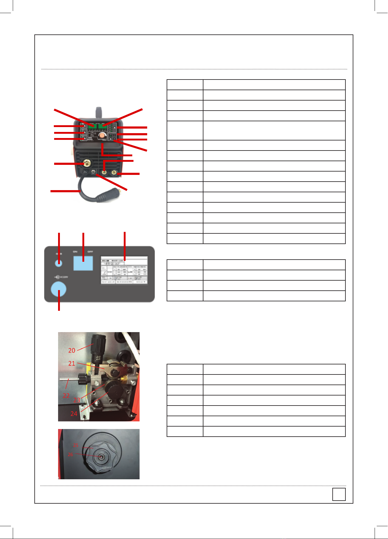
5.1.1 Fitting the spool
5.1.1.1 Open the cover door for the wire feed compartment. Remove the wire spool retainer (24) by
threading off anti clockwise.
5.1.1.2 Fit the 200mm diameter wire spool to the spool holder, ensuring the end of the wires exits towards the
wire feeder from the bottom of the spool. Ret the wire spool retainer (25) and tighten hand tight.
5.1.1.3 Set the spool brake tension by rotating the adjustment screw (26) using an Allen Key wrench. Clockwise
to increase brake tension, anti-clockwise to decrease brake tension. The spool brake tension should be set so
that the spool can rotate freely, but does not continue to rotate once the wire feed stops. This may need to be
adjusted as the wire is used up and the spool weight decreases.
5.1.2 Loading wire feeder
5.1.2.1 Release the wire feeder tension arm (21) by pivoting the wire feed tension adjuster (20) as pictured
below.
5.1.2.2 Check the wire drive roller (23) groove matches the selected MIG wire type and size. The drive roller will
have two different sized grooves; the size of the groove in use is stamped on the side of the drive roller. For ux
cored ‘soft’ wire, such as that used in gas less MIG welding, the drive roller groove has a serrated prot. For solid
‘hard’ MIG wire, the roller groove has a ‘v’ shaped prole.
5.1.2.3 The drive roller (23) is removed by threading the drive roller retainer(24) off in the anti-clockwise
direction. Once the correct drive roller prole is selected, re-t the drive roller.
5.1.2.4 Thread the MIG wire from the spool through the input guide tube (22), through the roller groove and into
the outlet guide tube.
5.1.2.5 Replace the tension arm (21) and the tension adjustment (20). Double check the wire has located
correctly in the drive roller groove.
5.1.2.6 Adjusting wire feed tension: this is accomplished by winding the knob on the wire tension adjustment
arm (20). Clockwise will increase tension, anti-clockwise will decrease tension. There is a numbered scale on
the tensioner to indicate the position. Ideal tension should be as little as possible, while maintaining a consistent
wire feed with no drive roller slippage. Check all other possible causes of slippage, such as; incorrect/ worn drive
roller, worn/ damaged torch consumables, blocked/ damaged torch feed liner, before increasing feed tension.
8

Inverter DC MIG Welder Manual www.gentt.ie
INSTALLATION
Warning! - Before changing the feed roller or wire spool, ensure that the mains power is
switched off
Warning! - The use of excessive feed tension will cause rapid and premature wear of the
drive roller, the support bearing and the drive motor.
!
5.1.3 Loading wire feeder
5.1.3.1 Connect the MIG Torch Euro Connector (28) to the torch socket on the front of the welder (11).
Secure by rmly hand tightening the threaded collar on the MIG Torch Euro Connector clockwise.
5.1.3.2 Check that the correct ux cored, gas less wire, matching drive roller (23) and welding tip (32)
are tted.
5.1.3.3 Connect Torch Connection Power Lead (14) to the negative (-) welding output terminal (13).
5.1.3.4 Connect Earth Lead Quick Connector (30) to the positive (+) output welding terminal (12).
See picture below:
5.1.4 Setup for gas shielded MIG welding operation
5.1.4.1 Connect the MIG Torch Euro Connector (28) to the torch socket on the front of the welder (11).
Secure by rmly hand tightening the threaded collar on the MIG Torch Euro Connector clockwise.
5.1.4.2 Check that the correct gas shielded wire; matching drive roller (23) and welding tip (32) are tted.
5.1.4.3 Connect Torch Connection Power Lead (14) to the positive (+) welding output terminal (12).
5.1.4.4 Connect Earth Lead Quick Connector (30) to the negative (-) output welding terminal (13).
See picture below:
5.1.4.5 Connect Earth Clamp (29) to the work piece. Contact with work piece must be strong contact with
clean, bare metal, with no corrosion, paint or scale at the contact point.
5.1.4.6 Connect the gas regulator (optional) and gas line to the inlet on the rear panel (18). If the regulator is
equipped with a ow gauge, the ow should be set between 8 – 15 L/minute depending on application. If gas
regulator is not equipped with a ow gauge, adjust pressure so gas can just be heard coming out of the torch
conical nozzle (31). It is recommended that gas ow is checked again, just prior to starting weld this can be
done by triggering the MIG torch with the unit powered up.
!
9

Inverter DC MIG Welder Manual www.gentt.ie
5.1.5 Setup for MMA/STICK mode operation
Note - MMA/Stick Welding requires an MMA lead set.
5.1.5.1 Connect Electrode holder Quick Connector to the positive (+) welding output terminal (12).
5.1.5.2 Connect Earth Lead Quick Connector (30) to the negative (-) output welding terminal (13).
See picture below:
5.1.6 Setup for Lift TIG welding operation
Note - TIG operation requires an argon gas supply, TIG torch, consumables.
5.1.6.1 Connect Lift TIG torch Quick Connector to the negative (-) output welding terminal (13).
5.1.6.2 Connect Earth Lead Quick Connector (30) to the positive (+) welding output terminal (12).
5.1.6.3 Connect the air hose of Lift TIG torch with the Argon meter connector. See picture below.
5.1.6.4 Connect Earth Clamp (29) to the work piece. Contact with work piece must be strong contact with
clean, bare metal, with no corrosion, paint or scale at the contact point.
INSTALLATION
10

Inverter DC MIG Welder Manual www.gentt.ie
INSTALLATION
Connection of Shield Gas
Connect the CO2 hose, which come from the wire feeder to the
copper nozzle of gas bottle. The gas supply system includes the gas
bottle, the air regulator and the gas hose, the heater cable should be
inserted into the socket of machine’s back, and use the hose clamp
to tighten it to prevent leaking or air-in, so that the welding spot is
protected.
1) Leakage of shielding gas affects the performance of arc welding.
2) Avoid the sun shine on the gas cylinder to eliminate the
possible explosion of gas cylinder due to the increasing pressure
of gas resulted from the heat.
3) It is extremely forbidden to knock at gas cylinder and lay the
cylinder horizontally.
4) Ensure no person is up against the regulator, before the gas
release or shut the gas output.
5) For MIG-250GW and MIG-250GF, insert the power supply plug
of the heater into the 36 VAC (5A) socket on the back panel of the
welding machine.
6) The gas output volume meter should be installed vertically to
ensure the precisely measuring.
7) Before the installation of gas regulator, release and shut the gas
for several time in order to remove the possible.
Note: Since the arc of MIG welding is much strong than that of MMA welding, please
wear welding helmet and protective clothing.
11

Inverter DC MIG Welder Manual www.gentt.ie
5.1.5 Controls for MIG Welding
INSTALLATION
5.1.5.1 Voltage meter: in MIG mode it shows setting voltage and welding voltage; in other modes no voltage
will be showed.
5.1.5.2 Gas selection: CO2--ordinary CO2 gas; MIX--20% CO2 80% argon; FLUX-- ux cored.
5.1.5.3 Function selection: 2T in MIG mode/4T in MIG mode; VRD in MMA mode.
5.1.5.4 Welding mode selection: MIG welding mode; TIG welding mode; MMA welding mode.
5.1.5.5 Current meter: in MIG mode it shows wire feed speed, welding current, inductance; in MMA mode it
shows current, hot start current, arc force current.
5.1.5.6 Wire diameter selection: in Synergy mode, select the wire diameter, press the 9 adjustment knob, the
voltage can be adjusted by ±1V; in Separate mode, welding current and welding voltage can be adjusted
separately--press the button one time to select voltage or current separate adjustment; This button cannot
work in MMA or TIG mode.
5.1.5.7 Gas check: gas check function, the button cannot work in MMA or TIG mode.
5.1.5.8 Wire check: wire fast feed button--short press this button.
5.1.5.9 Spool gun: weld by spool gun.
5.1.5.10 Adjustment knob: In MIG mode-- voltage adjustment, inductance adjustment, wire feed speed
adjustment, current adjustment; In MMA mode -- inductance adjustment, hot start current adjustment;
In TIG mode--current adjustment.
5.1.5.11 Mode selection: Hot start function, Arc force function, Inductance selection (Hot start function, the
voltage meter shows HOL; Arc force, the voltage meter shows FO).
Note: This MIG welding machine can be both synergic and separate, select the wire feed speed and the volt-
age parameter will be matched automatically.
Please select the wire diameter according to the wire you use.
Voltage rene initialization value is 0, rene the voltage by ±1V according to different kinds of gas.
In synergy mode, the base gas is CO2, to lower the voltage by 2-3V for mix gas.
Inductance initialization value is 0, adjust range ±10.
Note: For ux cored wire, connect the Polar conversion line to Negative (-) Welding Output Terminal, connect
the earth clamp to Positive (+) Welding Output Terminal; For ordinary wire, connect the Polar conversion line
to Positive (+) Welding Output Terminal, connect the earth clamp to Negative (-) Welding Output Terminal
Warning! - Disconnect the power supply when the Alarm light ash.
!
12

Inverter DC MIG Welder Manual www.gentt.ie
6 Welding settings quick reference chart
INSTALLATION
RPWMIG1400i Welding Settings Quick Reference Chart
Welding Parameter Material Thickness
Welding
Material Wire Type Polarity Wire
size Shielding Glass 1.0mm 2.0mm 3.0mm 4.0mm 5.0mm 6.0mm
Setting Key - Voltage/Wire Speed
Mild Steel Self Shielded Flux
Core Torch Negative (-) 0.8mm N/A - 14.0/2.7 16.2/3.0 18.5/6.1 24.5/9.0 -
Mild Steel Self Shielded Flux
Core Torch Negative (-) 0.9mm N/A - 16.3/2.0 18.8/3.6 20.2/4.1 21.0/7.5 21.6/9.0
Mild Steel Solid Wire
ER70S-6 Torch Positive(+) 0.6mm 75% Argon + 25% CO2 15.9/3.4 19.5/7.8 - - - -
Mild Steel Solid Wire
ER70S-6 Torch Positive(+) 0.8mm 75% Argon + 25% CO2 12.8/2.0 14.1/3.3 17.5/6.6 20.0/8.2 21.0/9.0 21.0/9.0
Mild Steel Solid Wire
ER70S-6 Torch Positive(+) 0.6mm 100% CO2 14.2/2.1 19.8/8.1 - - - -
Mild Steel Solid Wire
ER70S-6 Torch Positive(+) 0.8mm 100% CO2 13.6/2.3 14.4/3.6 18.4/4.2 21.1/8.5 22.6/9.0 -
Use this chart as a guide only, as original settings will vary with joint type and operator technique. Cells left blank are not a recommended conguration.
13

Inverter DC MIG Welder Manual www.gentt.ie
INSTALLATION
Basic welding guide
MIG (GMAW/FCAW) Basic Welding Technique
Two different welding processes are covered in this section (GMAW and FCAW), with the intention
providing the very basic concepts in using the MIG mode of welding, where a welding gun is hand held,
and the electrode (welding wire) is fed into a weld puddle, and the arc is shielded by an inert welding grade
shielding gas or inert welding grade shielding gas mixture.
GAS METAL ARC WELDING (GMAW): This process, also known as MIG welding, CO2 welding, Micro Wire
Welding, short arc welding, dip transfer welding, wire welding etc., is an electric arc welding process which
fuses together the parts to be welded by heating them with an arc between a solid continuous, consumable
electrode and the work. Shielding is obtained from an externally supplied welding grade shielding gas or
welding grade shielding gas mixture. The process is normally applied semi automatically.
FLUX CORED ARC WELDING (FCAW): This is an electric arc welding process which fuses together the
parts to be welded by heating them with wan arc between a continuous ux lled electrode wire and the work.
Shielding is obtained through decomposition of the ux within the tubular wire. Additional shielding may or
may not be obtained from an externally supplied gas or gas mixture. The process is normally applied semi
automatically; however the process may be applied automatically or by machine. It is commonly used to weld
large diameter electrodes in the at and horizontal position and small electrode diameters in all positions.
The process is used to a lesser degree for welding stainless steel and for overlay work.
14

Inverter DC MIG Welder Manual www.gentt.ie
INSTALLATION
Position of MIG Torch
The angle of MIG torch to the weld has an effect on the width of the weld.
The welding gun should be held at an angle to the weld joint. (See Secondary Adjustment Variables below) Hold
the gun so that the welding seam is viewed at all times. Always wear the welding helmet with proper lter lenses
and use the proper safety equipment.
CAUTION
Do not pull the welding gun back when the arc is established. This will create excessive wire extension (stick-out)
and make a very poor weld. . The electrode wire is not energized until the gun trigger switch is depressed. The
wire may therefore be placed on the seam or joint prior to lowering the helmet.
15

Inverter DC MIG Welder Manual www.gentt.ie
INSTALLATION
DISTANCE FROM THE MIG TORCH NOZZLE TO THE WORK PIECE.
The electrode wire stick out from the MIG torch nozzle should be between 10mm TO 20.0mm. This
discharge may vary depending on the type of joint that is being welded.
TRAVEL SPEED
The speed at which the molten pool travels inuences the width of the weld and penetration of the welding
run.
MIG WELDING (GMAW) VARIABLES
Most of the welding done by all processes is on carbon steel. The items below describe the welding.
Variables in short-arc welding of 24 Gauge (0.024”, 0.6mm) TO ¼” (6.4mm) mild sheet or plate. The applied
techniques and end results in the GMAW process are controlled by these variables.
PRESELECTED VARIABLES
Preselected variables upon the type of material being welded, the thickness of the material, the welding
position, the deposition rate and the mechanical properties. These variables are:
• Type of electrode wire.
• Size of electrode wire.
• Type of Gas (Not applicable to self-shielding wires FCAW).
• Gas Flow Rate (Not applicable to self-shielding wires FCAW).
Primary Adjustable Variables
These control the process after preselected variables have been found. They control the penetration, bead
width, bead height, arc stability, deposition rate and weld soundness. They are:
• Arc Voltage
• Welding current (wire feed speed)
• Travel speed
Secondary Adjustable Variables
These variables cause changes in primary adjustable variables which in turn cause the desired change in the
bead formation. They are:
1. Stick-out (distance between the end of the contact tube (tip) and the end of the electrode wire). Maintain
at about 10mm stick-out
2. Wire Feed Speed. Increase in wire feed speed increases weld current, Decrease in wire feed speed
decreases weld current.
3. Nozzle Angle. This refers to the position of the welding gun in relation to the joint. The transverse angle
is usually one half the included angle between plates forming the joint. The longitudinal angle is the angle
between the centre line of the welding gun and a line perpendicular to the axis of the weld. The longitudinal
angle is generally called the Nozzle Angle and can be either trailing (pulling) or leading(pushing). Whether
the operator is left handed or right handed has to be considered to realize the effects
of each angle in relation to the direction of travel.
16

Inverter DC MIG Welder Manual www.gentt.ie
INSTALLATION
Establishing the Arc and Making Weld Beads
Before attempting to weld on a nished piece of work, it is recommended that practice welds be made on
a sample metal of the same material as that of the nished piece
The easiest welding procedure for the beginner to experiment with MIG welding is the at position. The
equipment is capable of at, vertical and overhead positions.
For practicing MIG welding, secure some pieces of 16 or 18 gauge (0.06” 1.5mm or 0.08” 2.0mm) mild steel
plate 6” x 6” (150 x 150mm). Use 0.030” (0.8mm) ux cored gasless wire or a solid wire with shielding gas
Setting of the Power Source
Power source and Wire feeder setting requires some practice by the operator, as the welding plant has two
control settings that have to balance. These are the Wire speed control and the welding Voltage Control.
The welding current is determined by the Wire speed control, the current will increase with increase Wire
speed, resulting in a shorter arc. Less wire speed will reduce the current and lengthen the Increasing the
welding voltage hardly alters the current level, but lengthens the arc. By decreasing voltage, a shorter
arc is obtained with a little change in current level.
When changing to a different electrode wire diameter, different control settings are required. A thinner
electrode wire needs more Wire speed to achieve the same current level.
A satisfactory weld cannot be obtained if the Wire speed and Voltage settings are not adjusted to suit the
electrode wire diameter and the dimensions of the work piece.
If the Wire speed is too high for the welding voltage, “stubbing” will occur as the wire dips into the molten
pool and does not melt. Welding in these conditions normally produces a poor weld due to lack of fusion.
If, however, the welding voltage is too high, large drops will form on the end of the wire, causing spatter.
The correct setting of voltage and Wire speed can be seen in the shape of the weld deposit and heard by a
smooth regular arc sound. Refer to the Weld Guide located on the inside of the wire feed compartment door
for setup information.
Electrode Wire Size Selection
The choice of Electrode wire size and shielding gas used depends on the following:
• Thickness of the metal to be welded
• Capacity of the wire feed unit and Power Source
• The amount of penetration required
• The deposition rate required
• The bead prole desired
• The position of welding
• Cost of the wire
17

Inverter DC MIG Welder Manual www.gentt.ie
7. Range of welding current and voltage in CO2 welding
INSTALLATION
Wire O (mm) Short circuit transition Granular transition
Current (A) Voltage (V) Current (A) Voltage (V)
0.6 40 ~ 70 17 ~ 19 160 ~ 400 25 ~ 38
0.8 60 ~ 100 18 ~ 19 200 ~ 500 26 ~ 40
1.0 80 ~ 120 18 ~ 21 200 ~ 600 27 ~ 40
The option of the welding speed
The welding quality and productivity should be taken into consideration for the option of welding speed. In
case that the welding speed increases, it weakens the protection efciency and speeds up the cooling pro-
cess. As a consequence, it is not optimal for the seaming. In the event that the speed is too slow, the work
piece will be easily damaged, and the seaming is not ideal. In practical operation, the welding speed should
not exceed 1m/min.
-The length of wire stretching out
The length of wire stretching out the nozzle should be appropriate. The increase of the length of wire stretch-
ing out of the nozzle can improve the productivity, but if it is too long, excessive spatter will occur in the
welding process. Generally, the length of wire stretching out the nozzle should be 10 times as the welding
wire diameter.
The setting of the C02 ow volume
The protection efciency is the primary consideration. Besides, inner-angle welding has better protection
efciency than external-angel welding. For the main parameter, refer to the following gure.
Welding mode Thin wire C02 welding Thick wire C02 welding Thick wire, big current C02
welding
CO2 L/min 5 ~ 15 15 ~ 25 25 ~ 50
8. WELDING PARAMETERS TABLE
Option of C02 ow volume
The option of the welding current and welding voltage directly inuences the welding stability, welding quality
and productivity. In order to obtain the good welding quality, the welding current and welding voltage should
be set optimally. Generally, the setting of weld condition should be according to the welding diameter and the
melting form as well as the production requirement.
The following parameter is available for reference.
Parameter for butt-welding (Please refer to the following gure.)
g
2
1
18

Inverter DC MIG Welder Manual www.gentt.ie
Plate
thickness
t (mm)
Gap
g (mm)
Wire
O (mm) Welding
current (A)
Welding
voltage (V)
Welding
speed
(cm/min)
Gas volume
(L/min)
0.8 0 0.8~0.9 60 ~ 70 16 ~ 16.5 50 ~ 60 10
1.0 0 0.8 ~ 0.9 75 ~ 85 17 ~ 17.5 50 ~ 60 10 ~ 15
1.2 0 1.0 70 ~ 80 17 ~ 18 45 ~ 55 10
1.6 0 1.0 80 ~ 100 18 ~ 19 45 ~ 55 10 ~ 15
2.0 0 ~ 0.5 1.0 100 ~ 110 19 ~ 20 40 ~ 55 10 ~ 15
2.3 0.5 ~ 1.0 1.0 or 1.2 110 ~ 130 19 ~20 50 ~ 55 10 ~ 15
3.2 1.0 ~ 1.2 1.0 or 1.2 130 ~ 150 19 ~21 40 ~ 50 10 ~ 15
4.5 1.2 ~ 1.5 1.2 150 ~ 170 21 ~ 23 40 ~ 50 10 ~ 15
GASLESS
2.3 0.5 ~ 1.0 0.8/1.0 110 ~ 130 14 ~ 16 30~40/20~30 \
3.2 1.0 ~ 1.2 0.8/1.0 130 ~ 150 15 ~ 17 50~60/40~50 \
4.5 1.2 ~ 1.5 0.8/1.0 150 ~ 190 16 ~ 18 60~70/50~60 \
INSTALLATION
Parameter for butt-welding (Please refer to the following gure.)
I
t
19
This manual suits for next models
1
Table of contents