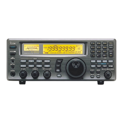
NIROS TRX1012 Series User manual

NIROS
COMMUNICATIONS A/S Copyright © 2004
File/Reference Prepared Date Revised by Revised date Revision No. Approved
manual for trx1012 TN 30-09-05 TN 30-09-05 8 PA
Manual for TRX1012


NIROS
COMMUNICATIONS A/S Copyright © 2004
File/Reference Prepared Date Revised by Revised date Revision No. Approved
manual for trx1012 TN 30-09-05 TN 30-09-05 8 PA
List of contents.
1. Technical specifications and introduction.
2. General user instructions.
3. Theory of hardware operation.
4. Basic software programming.
5. Maintenance/adjustment.
6. Mechanics.
7. TRX1012 Systemboard.
8. TRX1012 Display unit.
9. TRX1012 Keyboards.
10. TRX1012 Flexboard.
11. TRX1012B Radioboard.
12. TRX1012B Receiver.
13. TRX1012B VCO-board.
14. TRX1012C Radioboard.
15. TRX1012C Receiver.
16. TRX1012C VCO-board.
17. TRX1012D Radioboard.
18. TRX1012D Receiver.
19. TRX1012D VCO-board.
20. TRX1012D PA-modul.


NIROS
COMMUNICATIONS A/S Copyright © 2004
File/Reference Prepared Date Revised by Revised date Revision No. Approved
manual for trx1012 TN 30-09-05 TN 30-09-05 8 PA
1. Technical specifications and introduction ......................................................................1-1
1.1 NIROS TRX1012 - Technical specifications ..............................................................1-3
1.1.1 General ............................................................................................................................. 1-3
1.2 NIROS TRX1012B 125 - Specifications......................................................................1-4
1.2.1 General ............................................................................................................................. 1-4
1.2.2 Transmitter....................................................................................................................... 1-4
1.2.3 Receiver............................................................................................................................ 1-4
1.3 NIROS TRX1012B 200 - Specifications......................................................................1-5
1.3.1 General ............................................................................................................................. 1-5
1.3.2 Transmitter....................................................................................................................... 1-5
1.3.3 Receiver............................................................................................................................ 1-5
1.4 NIROS TRX1012B - Specifications ............................................................................. 1-6
1.4.1 General ............................................................................................................................. 1-6
1.4.2 Transmitter....................................................................................................................... 1-6
1.4.3 Receiver............................................................................................................................ 1-6
1.5 NIROS TRX1012C 125 - Specifications......................................................................1-7
1.5.1 General ............................................................................................................................. 1-7
1.5.2 Transmitter....................................................................................................................... 1-7
1.5.3 Receiver............................................................................................................................ 1-7
1.6 NIROS TRX1012C 200 - Specifications......................................................................1-8
1.6.1 General ............................................................................................................................. 1-8
1.6.2 Transmitter....................................................................................................................... 1-8
1.6.3 Receiver............................................................................................................................ 1-8
1.7 NIROS TRX1012C - Specifications ............................................................................. 1-9
1.7.1 General ............................................................................................................................. 1-9
1.7.2 Transmitter....................................................................................................................... 1-9
1.7.3 Receiver............................................................................................................................ 1-9
1.8 NIROS TRX1012DL 125 - Specifications..................................................................1-10
1.8.1 General ........................................................................................................................... 1-10
1.8.2 Transmitter..................................................................................................................... 1-10
1.8.3 Receiver.......................................................................................................................... 1-10
1.9 NIROS TRX1012DL 200 - Specifications..................................................................1-11
1.9.1 General ........................................................................................................................... 1-11
1.9.2 Transmitter..................................................................................................................... 1-11
1.9.3 Receiver.......................................................................................................................... 1-11
1.10 NIROS TRX1012DL - Specifications.......................................................................1-12
1.10.1 General ......................................................................................................................... 1-12
1.10.2 Transmitter................................................................................................................... 1-12
1.10.3 Receiver........................................................................................................................ 1-12
1.11 NIROS TRX1012DH 125 - Specifications ...............................................................1-13
1.11.1 General ......................................................................................................................... 1-13
1.11.2 Transmitter................................................................................................................... 1-13
1.11.3 Receiver........................................................................................................................ 1-13
1.12 NIROS TRX1012DH 200 - Specifications ...............................................................1-14
1.12.1 General ......................................................................................................................... 1-14
1.12.2 Transmitter................................................................................................................... 1-14
1.12.3 Receiver........................................................................................................................ 1-14
1.13 NIROS TRX1012DH - Specifications ......................................................................1-15
1.13.1 General ......................................................................................................................... 1-15
1.13.2 Transmitter................................................................................................................... 1-15
1.13.3 Receiver........................................................................................................................ 1-15
2. General user instructions..................................................................................................2-1

NIROS
COMMUNICATIONS A/S Copyright © 2004
File/Reference Prepared Date Revised by Revised date Revision No. Approved
manual for trx1012 TN 30-09-05 TN 30-09-05 8 PA
2.1 Handling instruction.....................................................................................................2-3
2.1.1 Connecting handmicrophone or autocassette to radio. ............................................. 2-3
3. Theory of hardware operation ...........................................................................................3-1
3.1 Technical description...................................................................................................3-3
3.1.1 PA Circuit......................................................................................................................... 3-3
3.1.2 Antenna switching, 2m and 4m...................................................................................... 3-3
3.1.3 Antenna switching, 0,7 m. .............................................................................................. 3-3
3.1.4 IF unit. .............................................................................................................................. 3-3
3.1.5 Syntheziser. ..................................................................................................................... 3-4
3.1.6 Power supply................................................................................................................... 3-5
3.1.7 Receiver, B-version (4 M). .............................................................................................. 3-5
3.1.8 Receiver, C-version (2 M). .............................................................................................. 3-5
3.1.9 Receiver, D-version (0,7 M). ........................................................................................... 3-5
3.1.10 VCO. ............................................................................................................................... 3-5
3.1.11 Programming with user program. ............................................................................... 3-6
3.1.12 Computer circuit. .......................................................................................................... 3-6
3.1.13 External control............................................................................................................. 3-6
3.1.14 AF-output amplifier. ...................................................................................................... 3-7
3.1.15 Modulation amplifier. .................................................................................................... 3-7
3.1.16 Tonesystem (Optional). ................................................................................................ 3-8
3.1.17 Interface. ........................................................................................................................ 3-8
3.1.18 Operation facilites......................................................................................................... 3-9
3.1.19 Connectors. ................................................................................................................... 3-9
3.1.20 Display unit.................................................................................................................... 3-9
4. Basic software programming ............................................................................................4-1
5. Maintenance/adjustment....................................................................................................5-1
5.1 Introduction. ..................................................................................................................5-3
5.2 Mechanical inspection and repair. .............................................................................5-3
5.2.1 Battery.............................................................................................................................. 5-3
5.2.2 Volume/ channel control. ............................................................................................... 5-3
5.2.3 Front and top keyboard.................................................................................................. 5-3
5.2.4 Side keys.......................................................................................................................... 5-4
5.2.5 Antenna connector. ........................................................................................................ 5-4
5.2.6 Display. ............................................................................................................................ 5-4
5.2.7 Flexboard. ........................................................................................................................ 5-4
5.3 Battery check. ...............................................................................................................5-4
5.4 Battery handling. ..........................................................................................................5-5
5.5 Service equipment........................................................................................................5-5
5.6 Radio adjustments........................................................................................................5-6
5.7 Transmitter power amplifier. .......................................................................................5-6
5.8 MF-unit. ..........................................................................................................................5-6
5.9 Reference and 2. local oscillator. ...............................................................................5-7
5.10 Loop filter. ...................................................................................................................5-7
5.11 Receiver. ......................................................................................................................5-8
5.12 VCO. .............................................................................................................................5-8
5.12.1 VCO check in transmitter mode:.................................................................................. 5-8
5.12.2 VCO check in receiver mode:....................................................................................... 5-8
5.12.3 VCO adjustment:........................................................................................................... 5-9
5.13 Display. ........................................................................................................................5-9
6. Mechanics ............................................................................................................................6-1
7. Systemboard TRX1012 .......................................................................................................7-1

NIROS
COMMUNICATIONS A/S Copyright © 2004
File/Reference Prepared Date Revised by Revised date Revision No. Approved
manual for trx1012 TN 30-09-05 TN 30-09-05 8 PA
7.1 Diagram .........................................................................................................................7-3
7.2 Componentside ............................................................................................................7-7
7.3 Wiringside .....................................................................................................................7-9
7.4 Fieldlist ........................................................................................................................7-11
7.5 Partlist..........................................................................................................................7-17
8. Display unit TRX1012 .........................................................................................................8-1
8.1 Diagram .........................................................................................................................8-3
8.2 Componentside ............................................................................................................8-5
8.3 Wiringside .....................................................................................................................8-7
8.4 Partlist unit No.5912.....................................................................................................8-9
8.5 Partlist unit No. 5910..................................................................................................8-11
8.6 Partlist unit No. 5911..................................................................................................8-13
9. Keyboards TRX1012 ...........................................................................................................9-1
9.1 Diagram .........................................................................................................................9-3
9.2 Componentside ............................................................................................................9-5
9.3 Wiringside .....................................................................................................................9-7
9.4 Diagram .........................................................................................................................9-9
9.5 Componentside ..........................................................................................................9-11
9.6 Wiringside ...................................................................................................................9-13
10. Flexboard TRX1012 ........................................................................................................10-1
10.1 Diagram .....................................................................................................................10-3
10.2 Componentside ........................................................................................................10-5
10.3 Partlist........................................................................................................................10-7
11. Radioboard TRX1012B...................................................................................................11-1
11.1 Diagram .....................................................................................................................11-3
11.2 Componentside ......................................................................................................11-13
11.3 Wiringside ...............................................................................................................11-15
11.4 Fieldlist ....................................................................................................................11-17
11.5 Partlist......................................................................................................................11-23
12. Receiver TRX1012B ........................................................................................................12-1
12.1 Diagram .....................................................................................................................12-3
12.2 Componentside ........................................................................................................12-5
12.3 Wiringside .................................................................................................................12-7
12.4 Partlist........................................................................................................................12-9
13. VCO-board TRX1012B....................................................................................................13-1
13.1 Diagram .....................................................................................................................13-3
13.2 Componentside ........................................................................................................13-5
13.3 Partlist........................................................................................................................13-7
14. Radioboard TRX1012C...................................................................................................14-1
14.1 Diagram .....................................................................................................................14-3
14.2 Componentside ......................................................................................................14-11
14.3 Wiringside ...............................................................................................................14-13
14.4 Fieldlist ....................................................................................................................14-15
14.5 Partlist......................................................................................................................14-21
15. Receiver TRX1012C ........................................................................................................15-1
15.1 Diagram .....................................................................................................................15-3
15.2 Componentside ........................................................................................................15-5

NIROS
COMMUNICATIONS A/S Copyright © 2004
File/Reference Prepared Date Revised by Revised date Revision No. Approved
manual for trx1012 TN 30-09-05 TN 30-09-05 8 PA
15.3 Wiringside................................................................................................................. 15-7
15.4 Partlist ....................................................................................................................... 15-9
16. VCO-board TRX1012C ................................................................................................... 16-1
16.1 Diagram..................................................................................................................... 16-3
16.2 Componentside........................................................................................................ 16-5
16.3 Partlist ....................................................................................................................... 16-7
17. Radioboard TRX1012D .................................................................................................. 17-1
17.1 Diagram..................................................................................................................... 17-3
17.2 Componentside...................................................................................................... 17-11
17.3 Wiringside............................................................................................................... 17-13
17.4 Fieldlist.................................................................................................................... 17-15
17.5 Partlist ..................................................................................................................... 17-21
18. Receiver TRX1012D ....................................................................................................... 18-1
18.1 Diagram..................................................................................................................... 18-3
18.2 Componentside........................................................................................................ 18-5
18.3 Wiringside................................................................................................................. 18-7
18.4 Partlist ....................................................................................................................... 18-9
19. VCO-board TRX1012D ................................................................................................... 19-1
19.1 Diagram..................................................................................................................... 19-3
19.2 Componentside........................................................................................................ 19-5
19.3 Partlist ....................................................................................................................... 19-7
20. PA-modul TRX1012D ..................................................................................................... 20-1
20.1 Diagram..................................................................................................................... 20-3
20.2 Componentside........................................................................................................ 20-5
20.3 Wiringside................................................................................................................. 20-7
20.4 Partlist ....................................................................................................................... 20-9

NIROS
COMMUNICATIONS A/S Copyright © 2004
File/Reference Prepared Date Revised by Revised date Revision No. Approved
manual for trx1012 TN 30-09-05 TN 30-09-05 8 PA
Revision log
Current revision
Revision No.
Revision log 8
Chapter 1 Technical specifications and introduction 1
Chapter 2 General user instructions 0
Chapter 3 Theory of hardware operation 0
Chapter 4 Basic software programming 0
Chapter 5 Maintenance/adjustment 0
Chapter 6 Mechanics 0
Chapter 7 Systemboard TRX1012 1
Chapter 8 Display unit TRX1012 0
Chapter 9 Keyboards TRX1012 0
Chapter 10 Flexboard TRX1012 0
Chapter 11 Radioboard TRX1012B 2
Chapter 12 Receiver TRX1012B 1
Chapter 13 VCO-board TRX1012B 1
Chapter 14 Radioboard TRX1012C 2
Chapter 15 Receiver TRX1012C 0
Chapter 16 VCO-Board TRX1012C 1
Chapter 17 Radioboard TRX1012D 2
Chapter 18 Receiver TRX1012D 0
Chapter 19 VCO-board TRX1012D 1
Chapter 20 PA-Modul TRX1012D 0
Revision 1 28-01-1999
Chapter 16 is changes to revision 1. New PC. Board version. D1, D2 and D5 is changed.
Revision 2 06-09-1999
Chapter 13 is changes to revision 1. New PC. Board version. D1, D2 and D5 is changed.
Revision 3 08-09-1999
Chapter 19 is changes to revision 1. New PC. Board version. D1, D2 and D5 is changed.
Revision 4 04-11-1999
Chapter 7 is changes to revision 1. New PC. Board version.
Chapter 11 is changes to revision 1. New PC. Board version.
Chapter 14 is changes to revision 1. New PC. Board version.
Chapter 17 is changes to revision 1. New PC. Board version.
Revision 5 14-02-2000
Chapter 17 is changes to revision 2. New PC. Board version.
Revision 6 22-12-2004
Chapter 12 is changes to revision 1. Update diagram.
Revision 7 22-06-2005
New Chapter 20. PA-modul TRX10012D.
Revision 8 30-09-2005
Chapter 1 is changes to revision 1. Update General specification.
Chapter 11 is changes to revision 2. Changes to TRX1001B Radioboard.
Chapter 14 is changes to revision 2. Changes to TRX1012C Radioboard.


NIROS
COMMUNICATIONS A/S Copyright © 2004
File/Reference Prepared Date Revised by Revised date Revision No. Approved
manual for trx1012 TN 30-09-05 TN 30-09-05 1 PA
1-1
1. Technical specifications and introduction


NIROS
COMMUNICATIONS A/S Copyright © 2004
File/Reference Prepared Date Revised by Revised date Revision No. Approved
manual for trx1012 TN 30-09-05 TN 30-09-05 1 PA
1-3
1.1 NIROS TRX1012 - Technical specifications
1.1.1 General
Frequency range: 68 - 88 MHz, 4 m
146 - 174 MHz. 2 m
403 - 470 MHz, 0,7 m
Bandwidth: VHF 4 m - 20 MHz
VHF 2 m - 28 MHz
UHF 0,7 m - 20 MHz
(Frequency for transmitter and receiver mutually
independent)
Modulation: FM/PM
Power source: NiCd battery 1000 mAh, NiMH battery 1500 mAh
or Li-ion battery 1350 mAh
Number of channels: 16 / 100 simplex, semi-duplex, reverse frequency
Channel spacing: 12,5 / 20 / 25 kHz
Channel selection: By keyboard or rotary switch
Channel selectivity: Better than 70 dB
Spurious and Harmonics: Less than 0.25 microwatt
RF power output: 1 - 4/5 Watt Individually programmable per channel
Receiver Sensitivity: Better than -114 dBm (0,7 m), -116 dBm (2m/4m),
0,45microV ½EMK 12 dB SINAD, (Typically -117 dBm,
0.32 microV ½ EMK)
AF Power output: 0.6 Watt peak, 0.35 W nominal, 0.3 Watt for external loudspeaker
Tone system: CCIR and ZVEI sequence tone with individual, group and general
call - CTSS. Individually programmable per channel. Other tone
systems as option.
Display: LCD with backlight.
1 line of 8 alphanumeric characters and 5 numeric with fixed
symbols showing chosen function and bargraph.
Keyboard: Foil keyboard with tactile keys and backlight.
4 large quick select function keys on front and 4 function keys on
top incl. emergency key on top..
Weight: 460/580 g incl. 1000 mAh battery and antenna.
Dimensions: H: 157 mm, W: 67 mm, D: 32 mm.
Temperature range: -25 to +55 (C
Housing Category: Die-cast metal cabinet better than IP54 dust and spray waterproof
R&TTE: EN 300 086-2, EN 301 489-5, EN 60 950
EMC: EN 50082-2 (industrial environment).

NIROS
COMMUNICATIONS A/S Copyright © 2004
File/Reference Prepared Date Revised by Revised date Revision No. Approved
manual for trx1012 TN 30-09-05 TN 30-09-05 1 PA
1-4
1.2 NIROS TRX1012B 125 - Specifications
1.2.1 General
Type designation TRX 1012B 125
Frequency band 68 - 88 MHz
Channel spacing 12,5 KHz
Number of channels 100
RF bandwidth 20 MHz
Mode of operation Simplex or semiduplex
Antenna impedance 50 ohms
Power supply NiCd battery, 7,2 V/ 1000 mAh
Ambient temperature Operates from -25°C to +55°C
Dimensions H: 157 mm, B: 67 mm, D: 32 mm
Weight with battery 480 g with 1000 mAh battery
Operating time (battery
full charged, 1000 mAh)
10,4 hours (5% TX (1 W), 5% RX (0,2 W), 90% STBY) 6,8
hours (5% TX (5 W), 5% RX (0,2 W), 90% STBY)
Frequency stability across voltage and
temperature ranges
+/-1,0 KHz
NOTE! All values are guaranteed specifications. Typical values are more favourable in most cases.
Environmental Meets IP54 specifications according to IEC 529
The serial number may be found on the rear side of the radio
1.2.2 Transmitter
Type designation TRX 1012B 125
RF output power 5 W, programmable between 1 and 5 W
Spurious and harmonic Less than -36 dBm
Adjacent channel power Less than -60 dBc
Modulation Phase modulation (PM), G3E
Max. freq. Deviation 2,5 KHz
AF response 300 to 2500 Hz
AF distortion Less than 7% at 1 KHz modulation freq. and 1,5 KHz deviation
Hum and noise Better than -40 dB
1.2.3 Receiver
Type designation TRX 1012B 125
EMF sensivity 20 dB SINAD (CEPT) 0,7 µVemf, typ. 0,6 µVemf (-116 dBm) (-118 dBm)
Adjacent channel rejection Better than -60 dB
Spurious and image rejection Better than -70 dB
Intermodulation rejection Better than -65 dB
AF output power 0,6 W to built-in loudspeaker
AF distortion Less than 10 % at 1000 Hz
AF response 300 - 2500 Hz, deemphasis 750 µsec, 6 dB/ octave
Hum and noise Better than -40 dB
Sound pressure Minimum 86 dBA, 1 KHz at 50 cm distance
All measurements according to ETSI standards ETS 300 086 and I-ETS 300 219.

NIROS
COMMUNICATIONS A/S Copyright © 2004
File/Reference Prepared Date Revised by Revised date Revision No. Approved
manual for trx1012 TN 30-09-05 TN 30-09-05 1 PA
1-5
1.3 NIROS TRX1012B 200 - Specifications
1.3.1 General
Type designation TRX 1012B 200
Frequency band 68 - 88 MHz
Channel spacing 20 KHz
Number of channels 100
RF bandwidth 20 MHz
Mode of operation Simplex or semiduplex
Antenna impedance 50 ohms
Power supply NiCd battery, 7,2 V/ 1000 mAh
Ambient temperature Operates from -25°C to +55°C
Dimensions H: 157 mm, B: 67 mm, D: 32 mm
Weight with battery 480 g with 1000 mAh battery
Operating time (battery
full charged, 1000 mAh)
10,4 hours (5% TX (1 W), 5% RX (0,2 W), 90% STBY) 6,8
hours (5% TX (5 W), 5% RX (0,2 W), 90% STBY)
Frequency stability across voltage and
temperature ranges
+/-1,35 KHz
NOTE! All values are guaranteed specifications. Typical values are more favourable in most cases.
Environmental Meets IP54 specifications according to IEC 529
The serial number may be found on the rear side of the radio
1.3.2 Transmitter
Type designation TRX 1012B 200
RF output power 5 W, programmable between 1 and 5 W
Spurious and harmonic Less than -36 dBm
Adjacent channel power Less than -70 dBc
Modulation Phase modulation (PM), G3E
Max. freq. Deviation 4,0 KHz
AF response 300 to 3000 Hz
AF distortion Less than 7% at 1 KHz modulation freq. and 2,4 KHz deviation
Hum and noise Better than -40 dB
1.3.3 Receiver
Type designation TRX 1012B 200
EMF sensivity 20 dB SINAD (CEPT) 0,7 µVemf, typ. 0,6 µVemf (-116 dBm) (-118 dBm)
Adjacent channel rejection Better than -70 dB
Spurious and image rejection Better than -70 dB
Intermodulation rejection Better than -65 dB
AF output power 0,6 W to built-in loudspeaker
AF distortion Less than 10 % at 1000 Hz
AF response 300 - 3000 Hz, deemphasis 750 µsec, 6 dB/ octave
Hum and noise Better than -40 dB
Sound pressure Minimum 86 dBA, 1 KHz at 50 cm distance
All measurements according to ETSI standards ETS 300 086 and I-ETS 300 219.

NIROS
COMMUNICATIONS A/S Copyright © 2004
File/Reference Prepared Date Revised by Revised date Revision No. Approved
manual for trx1012 TN 30-09-05 TN 30-09-05 1 PA
1-6
1.4 NIROS TRX1012B - Specifications
1.4.1 General
Type designation TRX 1012B
Frequency band 68 - 88 MHz
Channel spacing 25 KHz
Number of channels 100
RF bandwidth 20 MHz
Mode of operation Simplex or semiduplex
Antenna impedance 50 ohms
Power supply NiCd battery, 7,2 V/ 1000 mAh
Ambient temperature Operates from -25°C to +55°C
Dimensions H: 157 mm, B: 67 mm, D: 32 mm
Weight with battery 480 g with 1000 mAh battery
Operating time (battery
full charged, 1000 mAh)
10,4 hours (5% TX (1 W), 5% RX (0,2 W), 90% STBY) 6,8
hours (5% TX (5 W), 5% RX (0,2 W), 90% STBY)
Frequency stability across voltage and
temperature ranges
+/-1,35 KHz
NOTE! All values are guaranteed specifications. Typical values are more favourable in most cases.
Environmental Meets IP54 specifications according to IEC 529
The serial number may be found on the rear side of the radio
1.4.2 Transmitter
Type designation TRX 1012B
RF output power 5 W, programmable between 1 and 5 W
Spurious and harmonic Less than -36 dBm
Adjacent channel power Less than -70 dBc
Modulation Phase modulation (PM)
Max. Freq. Deviation 5,0 KHz
AF response 300 to 3000 Hz
AF distortion Less than 7% at 1 KHz modulation freq. and 3,0 KHz deviation
Hum and noise Better than -40 dB
1.4.3 Receiver
Type designation TRX 1012B
EMF sensivity 20 dB SINAD (CEPT) 0,7 µVemf, 0,6 µVemf (-116 dBm) (-118 dBm)
Adjacent channel rejection Better than -70 dB
Spurious and image rejection Better than -70 dB
Intermodulation rejection Better than -65 dB
AF output power 0,6 W to built-in loudspeaker
AF distortion Less than 10 % at 1000 Hz
AF response 300 - 3000 Hz, deemphasis 750 µsec, 6 dB/ octave
Hum and noise Better than -40 dB
Sound pressure Minimum 86 dBA, 1 KHz at 50 cm distance
All measurements according to ETSI standards ETS 300 086 and I-ETS 300 219.

NIROS
COMMUNICATIONS A/S Copyright © 2004
File/Reference Prepared Date Revised by Revised date Revision No. Approved
manual for trx1012 TN 30-09-05 TN 30-09-05 1 PA
1-7
1.5 NIROS TRX1012C 125 - Specifications
1.5.1 General
Type designation TRX 1012C 125
Frequency band 146 - 174 MHz
Channel spacing 12,5 KHz
Number of channels 16
RF bandwidth 28 MHz
Mode of operation Simplex or semiduplex
Antenna impedance 50 ohms
Power supply NiCd battery, 7,2 V/ 1000 mAh
Ambient temperature Operates from -25°C to +55°C
Dimensions H: 157 mm, B: 67 mm, D: 32 mm
Weight with battery 480 g with 1000 mAh battery
Operating time (battery
full charged, 800 mAh)
10,4 hours 5% TX (1 W), 5% RX (0,2 W), 90% STBY 6,1
hours 5% TX (5 W), 5% RX (0,2 W), 90% STBY
Frequency stability across voltage and
temperature ranges
+/-1,5 KHz
NOTE! All values are guaranteed specifications. Typical values are more favourable in most cases.
Environmental Meets IP54 specifications according to IEC 529
The serial number may be found on the rear side of the radio
1.5.2 Transmitter
Type designation TRX 1012C 125
RF output power 5 W, programmable between 1 and 5 W
Spurious and harmonic Less than -36 dBm
Adjacent channel power Less than -60 dBc
Modulation Phase modulation (PM), G3E
Max. freq. Deviation 2,5 KHz
AF response 300 to 2500 Hz
AF distortion Less than 7% at 1 KHz modulation freq. and 1,5 KHz deviation
Hum and noise Better than -40 dB
1.5.3 Receiver
Type designation TRX 1012C 125
EMF sensivity 20 dB SINAD (CEPT) 0,7 µVemf, typ. 0,6 µVemf (-116 dBm) (-118 dBm)
Adjacent channel rejection Better than -60 dB
Spurious and image rejection Better than -74 dB
Intermodulation rejection Better than -70 dB
AF output power 0,6 W to built-in loudspeaker
AF distortion Less than 10 % at 1000 Hz
AF response 300 - 2500 Hz, +1/ -3 dB, deemphasis 750 µsec, 6 dB/ octave
Hum and noise Better than -40 dB
Sound pressure Minimum 86 dBA, 1 KHz at 50 cm distance
All measurements according to ETSI standards ETS 300 086 and ETS 300 219.

NIROS
COMMUNICATIONS A/S Copyright © 2004
File/Reference Prepared Date Revised by Revised date Revision No. Approved
manual for trx1012 TN 30-09-05 TN 30-09-05 1 PA
1-8
1.6 NIROS TRX1012C 200 - Specifications
1.6.1 General
Type designation TRX 1012C 200
Frequency band 146 - 174 MHz
Channel spacing 20 KHz
Number of channels 16
RF bandwidth 28 MHz
Mode of operation Simplex or semiduplex
Antenna impedance 50 ohms
Power supply NiCd battery, 7,2 V/ 1000 mAh
Ambient temperature Operates from -25°C to +55°C
Dimensions H: 157 mm, B: 67 mm, D: 32 mm
Weight with battery 480 g with 1000 mAh battery
Operating time (battery
full charged, 800 mAh)
10,4 hours (5% TX (1 W), 5% RX (0,2 W), 90% STBY) 6,1
hours (5% TX (5 W), 5% RX (0,2 W), 90% STBY)
Frequency stability across voltage and
temperature ranges
+/-2,0 KHz
NOTE! All values are guaranteed specifications. Typical values are more favourable in most cases.
Environmental Meets IP54 specifications according to IEC 529
The serial number may be found on the rear side of the radio
1.6.2 Transmitter
Type designation TRX 1012C 200
RF output power 5 W, programmable between 1 and 5 W
Spurious and harmonic Less than -36 dBm
Adjacent channel power Less than -70 dBc
Modulation Phase modulation (PM), G3E
Max. Freq. Deviation 4,0 KHz
AF response 300 to 3000 Hz
AF distortion Less than 7% at 1 KHz modulation freq. and 2,4 KHz deviation
Hum and noise Better than -40 dB
1.6.3 Receiver
Type designation TRX 1012C 200
EMF sensivity 20 dB SINAD (CEPT) 0,7 µVemf, 0,6 µVemf (- 116 dBm) (-118 dBm)
Adjacent channel rejection Better than -70 dB
Spurious and image rejection Better than -70 dB
Intermodulation rejection Better than - 65 dB
AF output power 0,6 W to built-in loudspeaker
AF distortion Less than 10 % at 1000 Hz
AF response 300 - 3000 Hz, +1/ -3 dB, deemphasis 750 µsec, 6 dB/ octave
Hum and noise Better than -40 dB
Sound pressure Minimum 86 dBA, 1 KHz at 50 cm distance
All measurements according to ETSI standards ETS 300 086 and ETS 300 219.

NIROS
COMMUNICATIONS A/S Copyright © 2004
File/Reference Prepared Date Revised by Revised date Revision No. Approved
manual for trx1012 TN 30-09-05 TN 30-09-05 1 PA
1-9
1.7 NIROS TRX1012C - Specifications
1.7.1 General
Type designation TRX 1012C
Frequency band 146 - 174 MHz
Channel spacing 25 KHz
Number of channels 16
RF bandwidth 28 MHz
Mode of operation Simplex or semiduplex
Antenna impedance 50 ohms
Power supply NiCd battery, 7,2 V/ 1000 mAh
Ambient temperature Operates from -25°C to +55°C
Dimensions H: 157 mm, B: 67 mm, D: 32 mm
Weight with battery 480 g with 1000 mAh battery
Operating time
(battery full charged, 1000 mAh)
10,4 hours (5% TX (1 W), 5% RX (0,2 W), 90% STBY) 6,1 hours
(5% TX (5 W), 5% RX (0,2 W), 90% STBY)
Frequency stability across voltage and
temperature ranges
+/-2,0 KHz
NOTE! All values are guaranteed specifications. Typical values are more favourable in most cases.
Environmental Meets IP64 specifications according to IEC 529
The serial number may be found on the rear side of the radio
1.7.2 Transmitter
Type designation TRX 1012C
RF output power 5 W, programmable between 1 and 5 W
Spurious and harmonic Less than -36 dBm
Adjacent channel power Less than -70 dBc
Modulation Phase modulation (PM)
Max. freq. Deviation 5,0 KHz
AF response 300 to 3000 Hz
AF distortion Less than 7% at 1 KHz modulation freq. and 3,0 KHz deviation
Hum and noise Better than -40 dB
1.7.3 Receiver
Type designation TRX 1012C
EMF sensivity 20 dB SINAD (CEPT) 0,7 µVemf, typ. 0,6 µVemf (-116 dBm) (-118 dBm)
Adjacent channel rejection Better than -70 dB
Spurious and image rejection Better than -70 dB
Intermodulation rejection Better than -65 dB
AF output power 0,6W to built-in loudspeaker
AF distortion Less than 10 % at 1000 Hz
AF response 300 - 3000 Hz, +1/ -3 dB, deemphasis 750 µsec, 6 dB/ octave
Hum and noise Better than -40 dB
Sound pressure Minimum 86 dBA, 1 KHz at 50 cm distance
All measurements according to ETSI standards ETS 300 086 and I-ETS 300 219.

NIROS
COMMUNICATIONS A/S Copyright © 2004
File/Reference Prepared Date Revised by Revised date Revision No. Approved
manual for trx1012 TN 30-09-05 TN 30-09-05 1 PA
1-10
1.8 NIROS TRX1012DL 125 - Specifications
1.8.1 General
Type designation TRX 1012DL 125
Frequency band 403 - 445 MHz
Channel spacing 12,5 KHz
Number of channels 16
RF bandwidth 20 MHz
Mode of operation Simplex or semiduplex
Antenna impedance 50 ohms
Power supply NiCd battery, 7,2 V/ 1000 mAh
Ambient temperature Operates from -25°C to +55°C
Dimensions H: 157 mm, B: 67 mm, D: 32 mm
Weight with battery 480 g with 1000 mAh battery
Operating time (battery
full charged, 1000 mAh)
10,1 hours (5% TX (1 W), 5% RX (0,2 W), 90% STBY) 6,5
hours (5% TX (5 W), 5% RX (0,5 W), 90% STBY)
Frequency stability across voltage and
temperature ranges
+/-1,5 KHz
NOTE! All values are guaranteed specifications. Typical values are more favourable in most cases.
Environmental Meets IP54 specifications according to IEC 529
The serial number may be found on the rear side of the radio
1.8.2 Transmitter
Type designation TRX 1012DL 125
RF output power 5 W, programmable between 1 and 5 W
Spurious and harmonic Less than -36 dBm
Adjacent channel power Less than -60 dBc
Modulation Phase modulation (PM)
Max. freq. Deviation 2,5 KHz
AF response 300 to 2500 Hz
AF distortion Less than 7% at 1 KHz modulation freq. and 1,5 Khz deviation
Hum and noise Better than -40 dB
1.8.3 Receiver
Type designation TRX 1012DL 125
EMF sensivity 20 dB SINAD (CEPT) 0,9 µVemf, typ. 0,7 µVemf (- 114 dBm) (-116 dBm)
Adjacent channel rejection Better than -60 dB
Spurious and image rejection Better than -70 dB
Intermodulation rejection Better than -65 dB
AF output power 0,6 W to built-in loudspeaker
AF distortion Less than 10 % at 1000 Hz
AF response 300 - 2500 Hz, +1/ -3 dB, deemphasis 750 µsec, 6 dB/ octave
Hum and noise Better than -40 dB
Sound pressure Minimum 86 dBA, 1 KHz at 50 cm distance
All measurements according to ETSI standards ETS 300 086 and I-ETS 300 219.
This manual suits for next models
12
Table of contents

