Sky Master DVR 7500 User manual

OPERATING INSTRUCTIONS
Digital Harddisk Receiver
DVR 7500
Item-no. 39740

42
1. Content
39740
You have purchased a quality receiver from the SKYMASTER®programme. Our products are constantly subjected to
strict quality control to enable us to guarantee that you can enjoy our products. Welcome to the new era of digital
television! The SKYMASTER®DVR 7500 is a digital satellite receiver
Please note that you need a suitable digital satellite antenna to operate the SKYMASTER®DVR 7500. To be able to
receive ASTRA and EUTELSAT, it must be equipped with a Digital LNB.
1. Table of Contents . . . . . . . . . . . . . . . . . . . . . . . . 42
2. Features . . . . . . . . . . . . . . . . . . . . . . . . . . . . . . . 43
3. Safety Information . . . . . . . . . . . . . . . . . . . . . . . 43
4. Information about Direct Satellite Reception . . 44
5. Operating Elements . . . . . . . . . . . . . . . . . . . . . . 48
5.1 Front Panel . . . . . . . . . . . . . . . . . . . . . . . . . . . 48
5.2 Rear Panel . . . . . . . . . . . . . . . . . . . . . . . . . . . 48
6. Remote Control . . . . . . . . . . . . . . . . . . . . . . . . . 49
7. Connections . . . . . . . . . . . . . . . . . . . . . . . . . . . . 50
SAT Antenna Connection . . . . . . . . . . . . . . . . . . . 50
TV Set, VCR and Hi-Fi System Connection . . . . . . 51
8. On-Screen Display Menu (OSD) . . . . . . . . . . . . . 52
9. Installation/Settings . . . . . . . . . . . . . . . . . . . . . . 53
9.1 Antenna Configuration
DiSEqC 1.2 (Rotor Control) . . . . . . . . . . . . . . . 53
Fixed . . . . . . . . . . . . . . . . . . . . . . . . . . . . . . . 54
9.2 Channel Search . . . . . . . . . . . . . . . . . . . . . . . 55
9.3 System Settings . . . . . . . . . . . . . . . . . . . . . . . 56
9.4 Parental Control/Channel Lock . . . . . . . . . . . . 57
9.5 Factory Setting . . . . . . . . . . . . . . . . . . . . . . . 58
10. Daily Use: SAT TV and SAT Radio . . . . . . . . . . . 59
Select Channel . . . . . . . . . . . . . . . . . . . . . . . . . . . 59
TV/Radio Mode . . . . . . . . . . . . . . . . . . . . . . . . . . . 60
11. Channel Manager . . . . . . . . . . . . . . . . . . . . . . . . 62
Channel Manager . . . . . . . . . . . . . . . . . . . . . . . . . 62
Favourite Channels . . . . . . . . . . . . . . . . . . . . . . . . 63
Shift Channels . . . . . . . . . . . . . . . . . . . . . . . . . . . . 63
Lock Channels . . . . . . . . . . . . . . . . . . . . . . . . . . . 64
Rename Channels . . . . . . . . . . . . . . . . . . . . . . . . 64
Delete Channels . . . . . . . . . . . . . . . . . . . . . . . . . . 64
12. Hard Drive Recorder . . . . . . . . . . . . . . . . . . . . . . 65
Time-Shift Mode . . . . . . . . . . . . . . . . . . . . . . . . . 65
Recording . . . . . . . . . . . . . . . . . . . . . . . . . . . 65
Recording via REC . . . . . . . . . . . . . . . . . . . . . 65
Recording via PAUSE (Time-Shift) . . . . . . . . . 65
Stop Recording . . . . . . . . . . . . . . . . . . . . . . . 65
Playback/Slow-Motion . . . . . . . . . . . . . . . . . . 65
FF, REW (Search) . . . . . . . . . . . . . . . . . . . . . . 66
PAUSE (Single Step) . . . . . . . . . . . . . . . . . . . . 66
Playback whilst Recording . . . . . . . . . . . . . . . 66
Save and Stop . . . . . . . . . . . . . . . . . . . . . . . . 66
Info Bar . . . . . . . . . . . . . . . . . . . . . . . . . . . . . 66
Playback Mode . . . . . . . . . . . . . . . . . . . . . . . . . . . 67
Playback . . . . . . . . . . . . . . . . . . . . . . . . . . . . 67
Slow-Motion . . . . . . . . . . . . . . . . . . . . . . . . . 67
FF, REW, Pause, Jump . . . . . . . . . . . . . . . . . . 67
Timer Recording . . . . . . . . . . . . . . . . . . . . . . 67
EPG Recording . . . . . . . . . . . . . . . . . . . . . . . . 68
Simple Recording Overview . . . . . . . . . . . . . . 68
Video Manager Menu . . . . . . . . . . . . . . . . . . . . . . 68
Shift . . . . . . . . . . . . . . . . . . . . . . . . . . . . . . . . 68
Lock . . . . . . . . . . . . . . . . . . . . . . . . . . . . . . . 69
Rename . . . . . . . . . . . . . . . . . . . . . . . . . . . . . 69
Delete . . . . . . . . . . . . . . . . . . . . . . . . . . . . . . 69
Delete Hard Drive . . . . . . . . . . . . . . . . . . . . . 69
Jump . . . . . . . . . . . . . . . . . . . . . . . . . . . . . . . 69
Split and Join Recordings . . . . . . . . . . . . . . . 69
13. EPG (Electronic Programme Guide) . . . . . . . . . . 70
Extended EPG . . . . . . . . . . . . . . . . . . . . . . . . . . . . 70
14. Set Timer/Time . . . . . . . . . . . . . . . . . . . . . . . . . . 71
Set Date/Time . . . . . . . . . . . . . . . . . . . . . . . . . . . 71
15. Appendix
Antenna Configuration and Software Update . . 72
16. Games . . . . . . . . . . . . . . . . . . . . . . . . . . . . . . . . . 73
17. Information . . . . . . . . . . . . . . . . . . . . . . . . . . . . . .73
Reception of encrypted programmes . . . . . . . . . . .73
18. Technical Data . . . . . . . . . . . . . . . . . . . . . . . . . . 73
19. Trouble Shooting . . . . . . . . . . . . . . . . . . . . . . . . 74
20. SAT Glossary - Explanation of Technical Terms 75
21. Service . . . . . . . . . . . . . . . . . . . . . . . . . . . . . . . . 79
ATTENTION!
If the device is to be used to control systems which
are capable of receiving more than one satellite, use a
DiSEqC LNB instead of a universal LNB.

43
2. Performance characteristic
3. Safety Instructions
39740
Please read this safety information thoroughly before commissioning the device! Prolonged absence: In the
event of prolonged absence or thunderstorms, remove the mains plug of the device from the wall socket.
Also disconnect the antenna connections to avoid storm damage.
Cleaning: Remove the mains plug before cleaning the device. Use a dry or damp cloth and make sure that no
moisture penetrates the device!
Objects in the device: Make sure that no objects can enter the ventilation slots. There is risk of death through
electric shock!
Repair: Repairs must be performed by qualified experts. In the event of improper intervention by a third party, the
warranty will be voided and the safety of the device can no longer be guaranteed! Never open the housing of the
device yourself: Even when disconnected from the mains, there is an acute risk of death through electric shock.
Internal components can be damaged if touched.
Place of installation: Place the device on a straight and even surface. To protect the surface from being
discoloured as a result of the natural heat generated by the device, place the device on a suitable underlay.
Adequate ventilation: The ventilation slots on the device must never be covered. Ensure that the device has a
clearance of at least 10 cm at the sides and top, and that the heat can be dissipated upwards unimpeded.
External influences: Never expose the device to moisture (e.g. condensation or splash water) or direct sunlight. Do
not place the device in the vicinity of heat sources, such as e.g. heaters or devices that heat up.
Mains voltage: Use the equipment with the voltage specified on the case only! Do not plug the equipment into the
mains until all connection and installation work has been completed.
Earthing: Antenna systems must always be earthed, paying heed to the pertinent local and VDE regulations.
ASTRA, EUTELSAT, TÜRKSAT, DiSEqC and Skymaster are registered trademarks.
• New! Informative functional display for displaying
channel names
• Clearly arranged SAT radio station display with station
detection
• Future proof due to integrated common interfaces (CI) for
accepting two card reader modules (CAM)
• Simultaneously supports card reader modules of various
coding systems (Dolphin, Cryptoworks, Conax, Nagravsion,
Viaccess) for the reception of pay TV
• Simultaneous reception of uncoded and coded TV
channels/radio stations in connection with an appropriate
contract of a pay TV provider
• 5000 Programme memories (Radio/TV)
• 80GB hard drive for approx. 44 hours recording capacity
• Time shift recording and playback function
• Video recording via timer and EPG function
• Fast forward and rewind with 3 speeds (4 x, 8 x and 16 x)
• Extensive video post-editing functions
• Individual channel lists/favourites function
• User-friendly multilingual OSD
• Simple operation due to clearly arranged menu guidance
• Electronic Program Guide (EPG) with channel name and
extensive display of channel contents
• 800 page teletext memory
• Digital sound output, coaxial (SPDIF), for connection to home
cinema systems
• Operating and stand-by display
• Preprogrammed satellite positions for Astra, Eutelsat and
Türksat
• Various timer options
• Future-proof software update via satellite (OTA)
• Digital radio reception in CD quality
• Entertaining games
• Freeze and zoom function
• RGB output via Scart connection
• Separate video and stereo sound output
• DiSEqC®1.0 technology for LNB and multifeed control
• Additional rotor control due to DiSEqC®1.2 technology
• TV Scart output for connection to a TV set
• Additional Scart output for recording devices (VCR/DVR-R)
• S-Video output for high-quality playback
• Energy saving mains switch for stand-by mode
• Competent hotline service
Subject to technical changes
44
4. Information on direct satellite reception
39740
Selecting the antenna location.
Viewed from Europe, all TV satellites are located in the south, therefore you must select the installation location so
that the antenna points southwards. The satellite systems with the largest, freely receivable programme ranges are
ASTRA®(19.2° east) and HOTBIRD (13° east). Viewed from Central Europe, these satellite positions are located just
a few degrees east of the exact south direction.
S
HOTBIRD
ASTRA
When selecting the installation location, you must ensure that the
antenna is not covered by obstacles, such as e.g. bushes, trees, walls
or roof overhangs. Installation beneath the roof is not possible! The
antenna should be installed on a house wall protected from the wind,
if possible.
The necessary wall mounting is available as an accessory and is not
part of this system. If mounting on the roof, the antenna should be fixed
as low as possible on a mast.
The local VDE regulations, which prescribe potential and lightning
protection regulations, must be observed.
Alignment with a satellite.
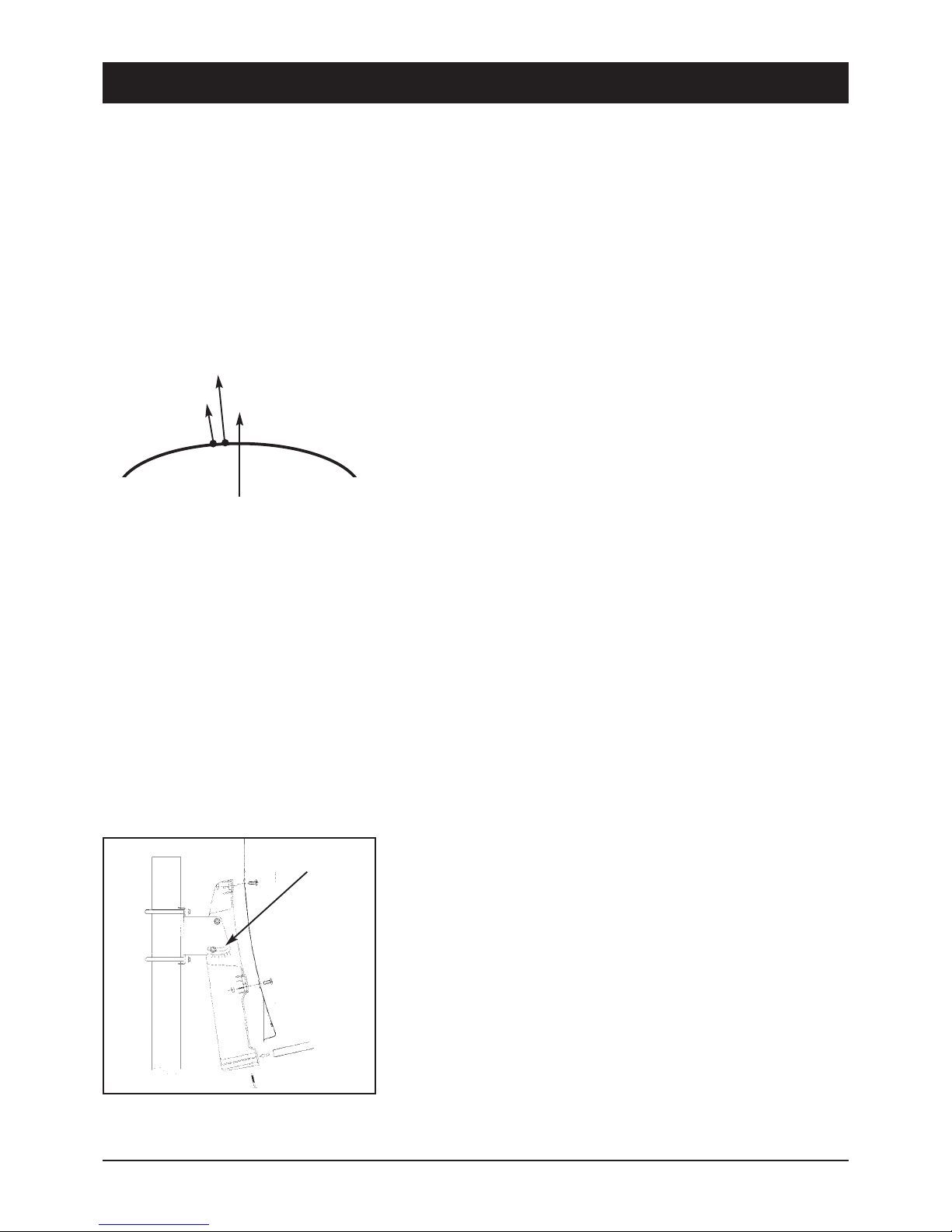
Leave the screws loose on the mast bracket until you have set the final position!
After fixing the antenna at its location, you should have it point southwards with the LNB in front.
The antenna height is set using the scale on the mounting plate. To set
the height, bend the antenna up and down carefully, until the desired
number of degrees is set.
The specified values can naturally only apply for vertically mounted
masts or wall brackets.
When setting the angle, do not pull on the LNB mounting arm
(risk of breaking!).
As illustration

45
4. Information on direct satellite reception
39740
EUROPA ASTRA 19,2° east HOTBIRD 13° east
Brussels 30,1 31,2
Sarajewo 39,4 39,1
Copenhagen 26,3 26,6
Tallinn 22,4 21,9
Helsinki 21,6 21,0
Marseilles 38,1 39,5
Paris 31,6 33,0
Athens 45,7 44,6
London 28,3 29,8
Edinburgh 23,2 24,6
Dublin 24,7 26,6
Milan 36,7 37,5
Rome 41,2 41,5
Zagreb 37,2 37,2
Riga 25,1 24,5
Wilna 27,4 26,7
Amsterdam 28,7 29,7
Oslo 21,7 22,0
Vienna 34,6 34,6
Salzburg 34,8 35,1
Warsaw 30,2 29,8
Lisbon 36,4 39,6
Stockholm 22,7 22,5
Bern 34,8 35,8
Bratislava 34,7 34,6
Ljubijana 36,8 37,0
Palma de Mallorca 41,1 43,0
Madrid 37,7 40,2
Prague 32,4 32,6
Budapest 35,4 35,1
GERMANY ASTRA 19,2° east HOTBIRD 13° east
Kiel 27,5 27,8
Hamburg 28,3 28,8
Rostock 27,9 28,3
Berlin 29,7 30,0
Bremen 28,6 29,2
Hanover 29,5 30,0
Düsseldorf 30,2 31,1
Kassel 30,6 30,9
Dresden 31,3 31,6
Wiesbaden 31,6 32,4
Nürnberg 32,8 33,3
Saarbrücken 32,3 33,2
Stuttgart 33,2 33,9
Munich 34,2 34,7
The following setting
angles apply for the
various locations:

46
4. Information on direct satellite reception
39740
For precise alignment of the antenna, the complete cabling must now be connected.
The television and the receiver should be located in the immediate vicinity of the antenna.
It is almost impossible to align the reception system by “shouting” e.g. from a distant television. A SAT finder (art.
no. 37351) or the signal strength indicator on a digital receiver is ideal for aligning the antenna.
Leave the equipment disconnected from the mains supply until cabling is complete!
Connect the antenna cable to the LNB. Carefully introduce the copper-coloured internal conductor of the cable into
the LNB socket. Place the thread of the plug directly onto the socket and screw the plug as tightly as you can by
hand. Fix the other end of the cable to the jack on the satellite receiver in the same way (LNB IN).
With a scart cable, connect the scart socket of the receiver (TV) to the scart socket of your television.
Your cabling now looks like this:
RECEIVER
LNB
SAT-ANTENNE
Please insert the provided batteries into the remote control.
Now connect your television and the receiver to the mains.
Press the Stand By button on the receiver or on the remote control.
It may be necessary to switch your television into so-called A/V mode. You can do this with the remote control on
your television. The procedure is different for each television unit. The relevant button could be marked 0, AV or
EXT. Please refer to the instructions for your television.
47
4. Information on direct satellite reception
39740
You must now move the preset antenna in millimetre steps, with the screws only hand-tight. Please note that there
must not be any obstacles between antenna and reception direction, and that you must not stand in front of the
antenna area. When you have mounted the antenna precisely southwards, as described above, and have set a
height angle as specified in the table, turn the antenna slowly to the left, i.e. to the east. (If the antenna is being
installed in Eastern Europe, turn it slowly to the west).
When moving the antenna, observe the screen or any signal indications provided (e.g. Sat finder/Digital receiver).
When a signal/TV picture appears, switch between a few programmes on the receiver to check whether the
antenna is aligned to the correct satellite. When the signal quality has reached its maximum, you should also
move the height angle up and down slightly, in the smallest steps, to further optimise the quality.
If you do not obtain any reaction or only a weak signal level, you should alter the height angle by a few millimetres
up or down and start the satellite search again by swivelling to the side.
When you have optimally set the antenna, tighten the screws on the antenna. Observe the screen at the same time,
as sometimes the antenna is moved slightly during fixing and the signal strength decreases again.
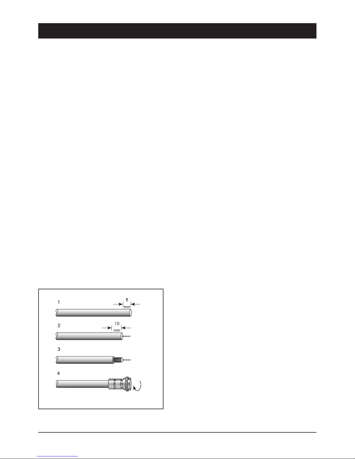
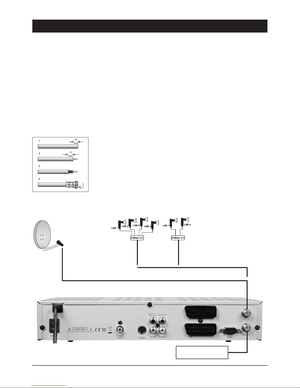
Fitting an F-plug, if you need to shorten your cable
IMPORTANT: Please proceed with great caution when fitting the F-plug. Failure to comply with the following instruc-
tions could cause malfunctions or destruction of the SAT receiver!! – Please use only continuous antenna cables.
• Strip the cable for a length of 8mm as far as the internal
conductor (with a sharp knife).
• Remove the protruding wires of the shielding braid.
• Remove 10 mm of the plastic casing until the shielding braid
is bared.
• Make sure that no wires of the shielding braid can touch the
internal conductor.
• Carefully screw the F-plug onto the cable, until the internal
conductor terminates flush with the front edge of the F-plug.
The shielding braid is now connected to the F-plug.
• Check the F-plug for short circuits. Look into the F-plug from
the front; the internal conductor must be located on its own in
the centre and must not be touched by any wires of the
shielding braid!
48
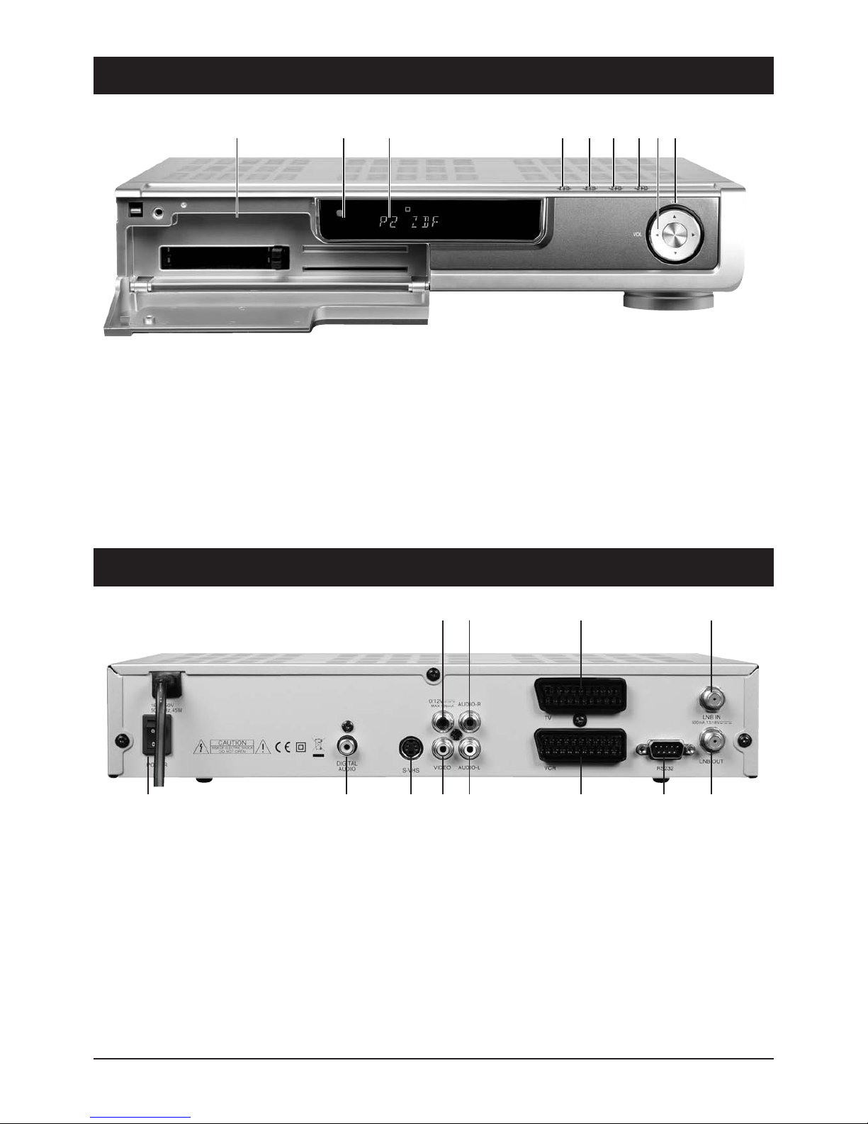
5.1 Operating elements, front of device
5.2 Operating element: Rear side of device
39740
13 5 7
2
4 6 8
11 12 109
1. LNB IN: LNB connection
2. LNB OUT: A further receiver can be connected here.
3. 0/12V Output: Connection for an additional switching
relay for antenna selection.
4. VIDEO OUTPUT: Connection for VCR or video sender.
5. AUDIO Right (red): Audio output R.
6. AUDIO Left (white): Audio output L.
7. TV SCART: TV connection.
8. VCR SCART: VCR connection.
9. S/PDIF: Optical digital output.
10.RS232: Service interface.
11. Power Switch:
12.S-VHS: High quality video output
32 789 14 5 6
1. Functional display for displaying channel names
2. IR receiver for remote control
3. On/Off switch (Stand By mode)
4. Menu
5. OK
6. Exit
7. Volume
8. Programme advance
9. 2x CAM module slots in PCMCIA standard
49
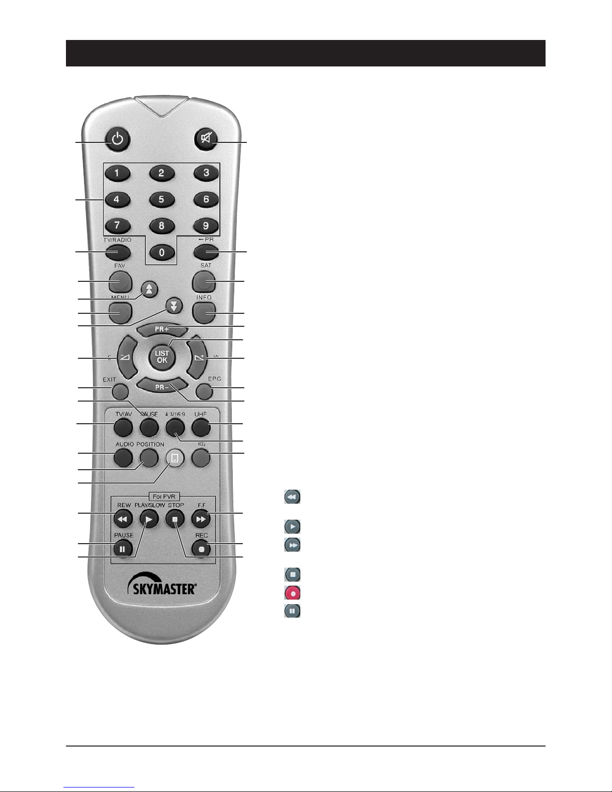
6. Remote control unit (RCU)
39740
1. POWER button Switches the device on or into standby.
2. Mute button Mutes or activates the sound.
3. UHF button OPTIONAL – no function.
4. 4:3/16:9 button Switches between 4:3 format and 16:9 format.
5. Number buttons (0 - 9) Use to select the TV or radio channel and
individual menu options.
6. RECALL button Returns to the last selected programme position.
7. INFO button Switches the info box for programme information
either on or off.
8. EPG button Displays the EPG (Electronic Programme Guide) if this
service is available.
9. TV/Radio button Use to select between TV and radio reception.
10. MENU button Displays the screen menu or returns to the previous
menu from a submenu.
11. SOUND button Use to select the audio mode
(stereo/mono/left/right or digital sound).
12. V+/V- buttons Sets the volume (in some menus the scrolling
function).
13. PR+/PR- buttons Use to select the next/previous programme
position. Use to select submenus in the main menu.
14. OK button Displays the channel list or selects menu items.
15. FAV button Displays the favourite list.
16. EXIT button Use to exit the menu or info box.
17. TELETEXT button Enables teletext reception of the selected
channel (for TV without teletext) and subtitles.
18. Button Fast rewind or reverse search during delayed
recording or playback.
19. Button Playback at normal speed without slow-motion.
20. Button Fast forward or forward search during delayed
recording or playback.
21. Stop button Stops recording or playback.
22. Recording button Starts immediate recording.
23. Button Pause and time-shift recording.
24. SAT button Switches between various SAT positions.
25. TV/AV Connects the VCR signal to a TV.
26. POSITION Use to control a DiSEqC-rotor.
27. PAGE Use to leaf page-for-page through programme lists.
28. ALT AUDIO Use to select various audio channels (e.g. languages).
29. PAUSE OPTIONAL – no function.
While inserting the cells please ensure that the
polarity is right! The polarity is denoted in the
cell area. Cells: 2 cells, size AAA, UM-4,
consumed micro or R03 cells constitute
special waste – please dispose them properly!
Reach, app. 6 m.
1 2
11
24
6
13
13
12
8
5
15
12
7
14
20
22
3
4
21
9
25
23
26
17
19
27
27
28
16
29
18
10
50
7. Connections
39740
Connection to the SAT antenna
The DiSEqC technology allows a large number of connection variants e.g.:
• A permanently aligned SAT antenna
• Two permanently aligned SAT antennae or Multifeed antennae with DiSEqC 2-way switch (art. no. 3932)
• 4 permanently aligned SAT antennae with a DiSEqC 4-way switch (art. no. 3934)
• 2 permanently aligned Multifeed antennae with DiSEqC 4-way switch (art. no. 3934)
• A rotating DiSEqC 1.2 rotor system, combined with several permanently aligned antennae
TIP: One or more Digital LNBs (reception converters) are required to receive satellite programmes. The
following technical data should be stated on the adhesive label of the LNB: 10.6GHz (or 10,600 MHz) and 9.75GHz
(or 9,750MHz) for the so-called oscillator frequencies. No other values or data are relevant, and the receiver is
ready for operation after connection.
Proceed with the utmost caution when preparing the antenna cable! As voltages and switching signals are transpor-
ted via the antenna cable, you must make sure that the shielding braid and the aluminium foil have good contact
with the F-plug and that no short-circuit occurs in the internal conductor of the cable!
After screwing on the F-plug, check that the internal conductor is not being touched
by any of the wires of the shielding braid.
A signal strength indicator is provided for aligning the antenna. Slowly swivel the
antenna southwards, observing the signal display on the screen. If you cannot find a
signal, change the inclination of the antenna a little. When aligning for the first time, it
is advisable to directly connect the antenna and receiver using the shortest possible
antenna cable, in order to exclude potential error sources
Additional SAT receiver
Examples:
Permanently installed
antenna or rotor-controlled
DiSEqC 1.2 system… …or for 2 or 4 SAT antennae to one connection
DiSEqC switch 4/1
art. no. 3934
DiSEqC switch 2/1
art. no. 3932
51
7. Connections
39740
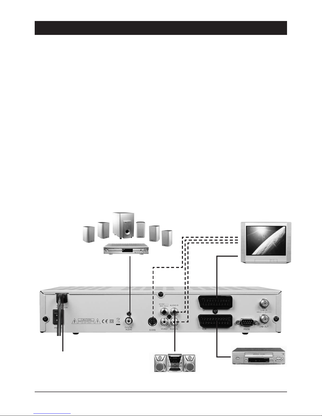
Connecting to the TV unit
You use a SCART cable for connecting to the TV set. If you have a TV with a 16:9 screen, for example, you can
adjust the settings to match your TV set in the receiver's screen menu. The default screen format is 4:3.
If your TV set does not have a Scart socket, use an appropriate adapter or use the 3 cinch outputs.
xxxx x x xx xxx xxx
Connecting to a video recorder
Connect the video recorder and the satellite receiver using a Scart cable. By means of the Scart socket it is possible
to record SAT programmes and to loop the playback of video cassettes through to the TV Scart socket.
If your video recorder does not have a Scart socket, use an appropriate adapter or use the 3 cinch outputs
Connecting to a stereo system
Analogue: The sound of the TV and radio programmes can be reproduced via your stereo system.
Connect the two audio cinch sockets to a free input of your hi-fi system (e.g. AUX, Line IN, CD or Tuner). Inputs with
the designation “Phono” are not suitable!
Digital: Connect the receiver and your AC3/surround system to the coaxial digital output of the SAT receiver.
VCR
TV
AC3/SURROUND (coaxial)
HIFI
230 V
52
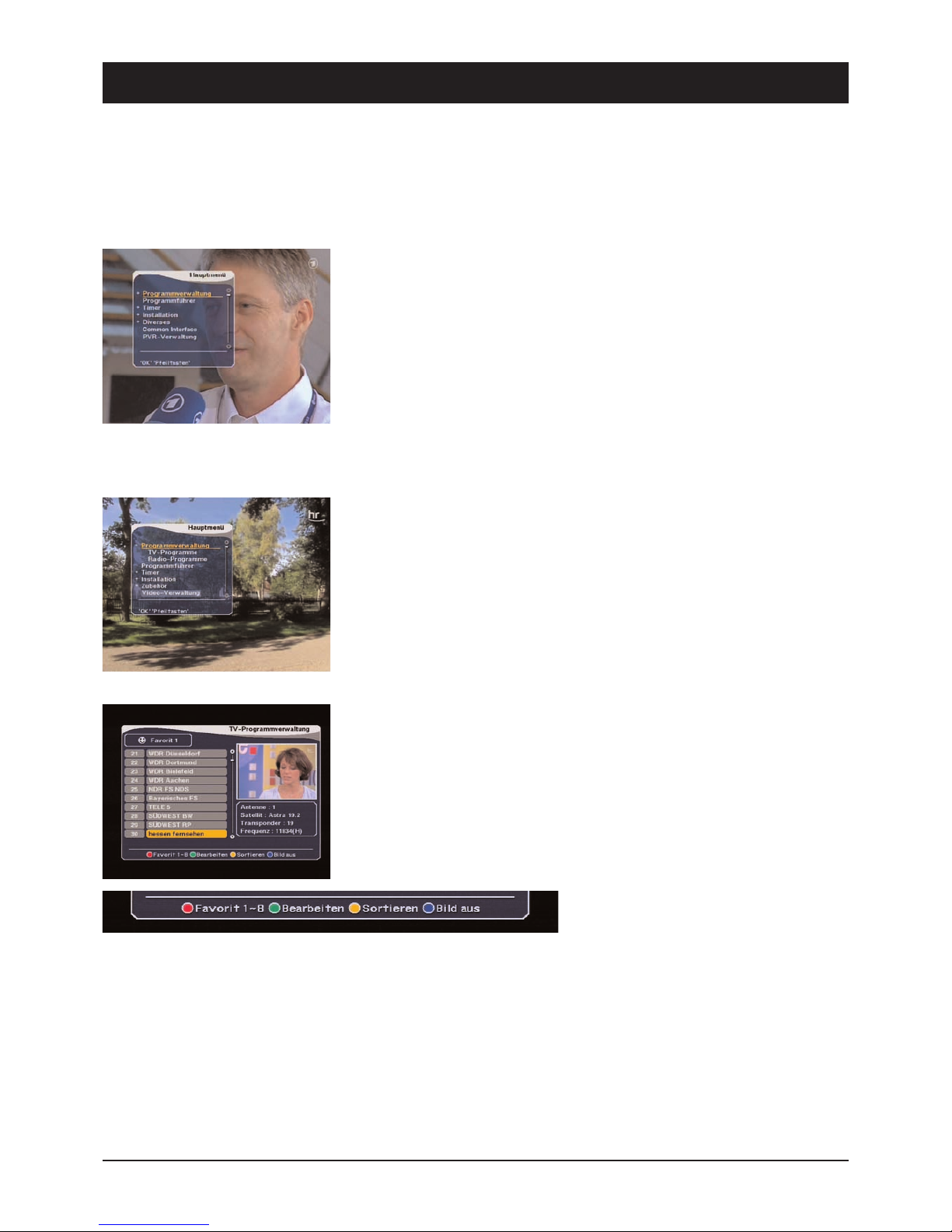
8. On-Screen Display Menu (OSD)
39740
A preset ASTRA satellite TV channel will appear after switching on the DVR once
installation has been completed and the DVR 7500 has been connected to all the
devices. In order to carry out changes to the presettings, press MENU on the
remote control to open the main menu:
The main menu displays the following selection options:
- Programme Manager
- Electronic Programme Guide (EPG)
- Timer
- Installation
- Accessories
- Common Interface
- Video Manager
Press OK to activate the desired menu item or to open a further submenu.
Submenus are concealed behind the selection options marked with a “+”. These
can be shown and re-concealed by pressing OK.
Press PR- and PR+ to select any visible menu item and activate via OK.
At the bottom of all the menus there is an overview of all the buttons via which
functions can be carried out in the current menu. In the displayed graphic it is
possible to carry out the functions “process” and “sort” via the green and yellow
button respectively.
Press EXIT to exit a displayed menu or to return from a submenu to a higher order
menu or to the television picture.
Changes to the settings are usually automatically accepted after exiting the menu.
In some cases a safety query, e.g. “Do you really wish to change the start
channel?”, appears. Use PR to select the desired option “OK” or “Cancel”. The
option marked yellow is carried out via OK.
53
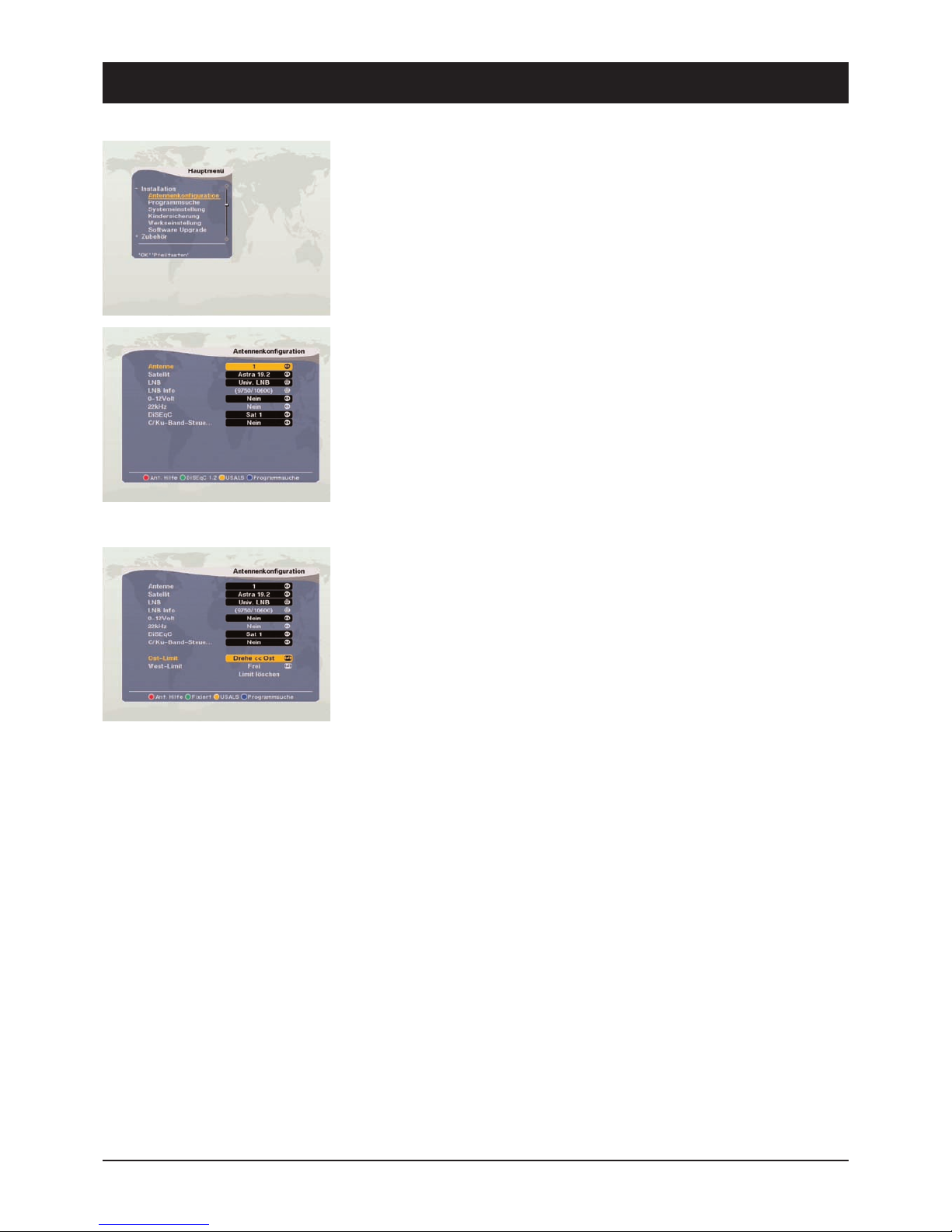
9. Installation/Settings
39740
The selection INSTALLATION contains the following 6 submenus:
- Antenna Configuration
- Programme Search
- System Setting
- Parental Control
- Factory Setting
- Software Upgrade
Antenna Configuration
Pay attention to the lower part of the on-screen image during antenna selection.
Press the coloured buttons to obtain the following possibilities:
Red: Ant. help, for calculating the elevation angle and angle of direction for fixed
satellite antennas
Green: DiSEqC 1.2-rotor or fixed satellite antenna
Yellow: For USALS rotors, for automatic calculation of each SAT position
Blue: Opens the programme search menu
9.1 Antenna Configuration DiSEqC 1.2 (Rotor Control)
If you do not have a DiSEqC 1.2-rotor, please proceed to the next section and read
“Fixed Antenna Configuration” on the next page.
When setting the DiSEqC-rotor, press the green button to obtain the menu on the
left.
1) Antenna: Carry out up to 16 different antenna configurations in connection with
various SAT change-over switches.
2) Satellite: Select the satellite to be received.
3) LNB: Digital LNBs are now a standard feature. If you are using an older or exotic
LNB, enter the changes manually. Only change the values if you are familiar
with the LNB technical data!
4) LNB info: Display of LNB frequencies (lower and upper oscillator frequency of
the LNB). The values for commercially available Digital LNBs are 9750
(oscfreq. LNB1) and 10600 (oscfreq. LNB2). Only change these values if the
assembly instructions for the satellite system clearly demand it!
5) SAT switch 0/12 volt and 22 kHz: Here it is possible to set which change-over
switch and switching pulse is to be used to receive various satellites. 0/12 volt
and 22 kHz change-over switches no longer figure in digital reception systems!
To prevent malfunctioning, set the settings for both types of change-over switch
to “No”.
6) SAT switch DiSEqC: Use a 2-way or 4-way DiSEqC switch, set here via which
input of the DiSEqC switch you wish to receive the satellite. The inputs of the
DiSEqC change-over switch are marked accordingly (1, 2, 3, 4 or A, B ...).
7) C/Ku-band: To prevent malfunctioning, leave the “No” setting. The C-band is
mainly received in the Middle East or Russia.

8) East/West limits: Use this function to fix the eastern and western swivel range
of the rotatable DiSEqC 1.2 or USALS antenna. This prevents the antenna being
damaged by obstacles (e.g. walls, branches) when rotating .
Press the E to rotate the antenna and confirm the position via OK. A query
subsequently appears which should be answered with either “OK” or “Cancel”.
Repeat the process to fix the western limit by holding down the W button until
the western position of the antenna has been reached. Confirm the subsequent
query via OK.
9) Cancel limits: Select the option “Delete Limits” and press OK in order to cancel
the stored east and west limits.
Caution: The DiSEqC-rotor is now able to move unhindered! The antenna could be
damaged by obstacles such as railings, branches or walls!
Once all the changes have been carried out, press Exit and confirm the safety
query via OK; this ensures that all the changes become effective.
9.1 Antenna Configuration - Fixed
To set a fixed antenna press, if necessary, the green button to obtain the menu on
the left. The options for the DiSEqC-rotor should no longer be displayed.
1) Antenna: Carry out up to 16 different antenna configurations in connection with
various SAT change-over switches.
2) Satellite: Select the satellite to be received.
3) LNB: Digital LNBs are now a standard feature. If you are using an older or exotic
LNB, enter the changes manually. Only change the values if you are familiar
with the LNB technical data!
4) LNB info: Display of LNB frequencies (lower and upper oscillator frequency of
the LNB). The values for commercially available Digital LNBs are 9750
(oscfreq. LNB1) and 10600 (oscfreq. LNB2). Only change these values if the
assembly instructions for the satellite system clearly demand it!
5) SAT switch 0/12 volt and 22 kHz: Here it is possible to set which change-over
switch and switching pulse is to be used to receive various satellites. 0/12 volt
and 22 kHz change-over switches no longer figure in digital reception systems!
To prevent malfunctioning, set the settings for both types of change-over switch
to “No”.
54
9. Installation/Settings
39740

55
9. Installation/Settings
39740
6) SAT switch DiSEqC: Use a 2-way or 4-way DiSEqC switch, set here via which
input of the DiSEqC switch you wish to receive the satellite. The inputs of the
DiSEqC change-over switch are marked accordingly (1, 2, 3, 4 or A, B ...).
7) C/Ku-band: To prevent malfunctioning, leave the “No” setting. The C-band is
mainly received in the Middle East or Russia.
Once all the changes have been carried out, press Exit. All the changes are
accepted when exiting the menu.
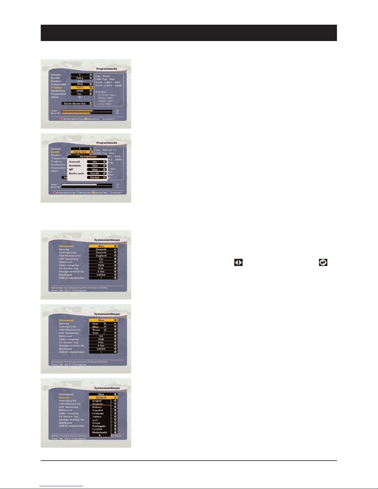
9.2 Channel Search
1) Antenna: Select one of the 16 antenna configurations.
2) Satellite: When selecting the desired satellite, press the volume buttons or OK to
display a selection list. There is information about the selected satellite on the
right hand side of the OSD.
3) Position (only for antenna configuration DiSEqC 1.2): Once the satellite has been
selected, select “Position”. Hold down E or W until satellite reception is
displayed by both bars (signal strength and quality). If the satellite has been
detected, the bar colour changes to yellow. The height of the value depends on
the reception strength of the actual satellite being searched in the respective
region and can vary greatly.
IMPORTANT:
Please always observe the assembly instructions of the DiSEqC-rotor! Prior to
searching for the satellite positions, the antenna and rotor's elevation angle and
angle of direction have to be placed in a specified basic position. Satellites located
further to the east or west will not be received if assembly has not been carried out
correctly!
4) Transponder: Here it is possible to select a stored transponder of the selected
satellite. This is necessary if you only wish to search for a specific transponder
or if a transponder is no longer active.
EDIT MODE: If you wish to change the pre-programmed values of a transponder
such as frequency, symbol rate, polarisation, 22 kHz etc., press the yellow button to
display the command box. Now press OK to activate the change mode. It is now
possible to select and change all the available selection options via the control
buttons.
It is also possible to delete the displayed transponder (“Delete TP”) and to change
the name of the satellite (“Rename Sat”).
56
9. Installation/Settings
39740
When manually changing or adding a transponder, the frequency (5-digit in MHz),
the polarisation horizontal or vertical (H/V) and the symbol rate (SR, usually 5-digit
27500 or 20000) have to be known. Obtain these values from satellite operators or
from TV and specialist magazines.
Start search: Go to “Search this Sat.” to start the search, or press the volume
buttons to search for all the available channel packages or just the displayed
transponder. The search commences after pressing OK.
Extended programme search: Press the blue button to receive the following
additional search options, which can be changed via the volume buttons:
Selection: It is possible to select certain satellites from an overview.
Sorting: According to FTA (Free to Air channels first), CAS (coded channels) or in
alphabetical order.
NIT: Some satellites such as Astra or Hotbird transmit a Network Information Table
(NIT). This is an up-to-date and complete channel table which can be read by the
receiver.
Search for: Satellite or transponder or programme ID selection.
9.3 System Settings
In this menu it is possible to change OSD presettings and to adjust the receiver to
its “technical environment” (TV/VCR…). Carry out the selection and changes via the
control buttons and OK. For the marking use the control buttons and for OK
for a select menu.
OSD Colour: Select a colour for all the screen menu displays.
OSD Language: Select a language for all the screen menu displays.
Audio Language: Here it is possible to set a sequence of certain languages which
should be heard for multi-lingual programmes.
Subtitle Language: Here it is possible to set a sequence of certain languages
which should be displayed as subtitles for multi-lingual programmes.
LNB Voltage: The LNB supply voltage should always be switched on. This way the
receiver supplies the required switching and supply voltages to the LNB, the
change-over switch and distributor. The option “LNB Voltage OFF” should only be
selected if it is clearly stated in your SAT system instructions!
Screen Format: Set the screen format of your TV here. The width-to-height ratios
57
9. Installation/Settings
39740
Video Output: For setting the output signal at the Scart sockets.
FBAS (also: composite) is compatible with all normal TV sets and VCRs, RGB is of
higher quality, but is not yet supported by every TV set.
Type of TV: The colour standard in Europe is - apart from a few exceptions - PAL.
NTSC is used in the USA and Japan.
Visible Display: Setting of the display period for channel information.
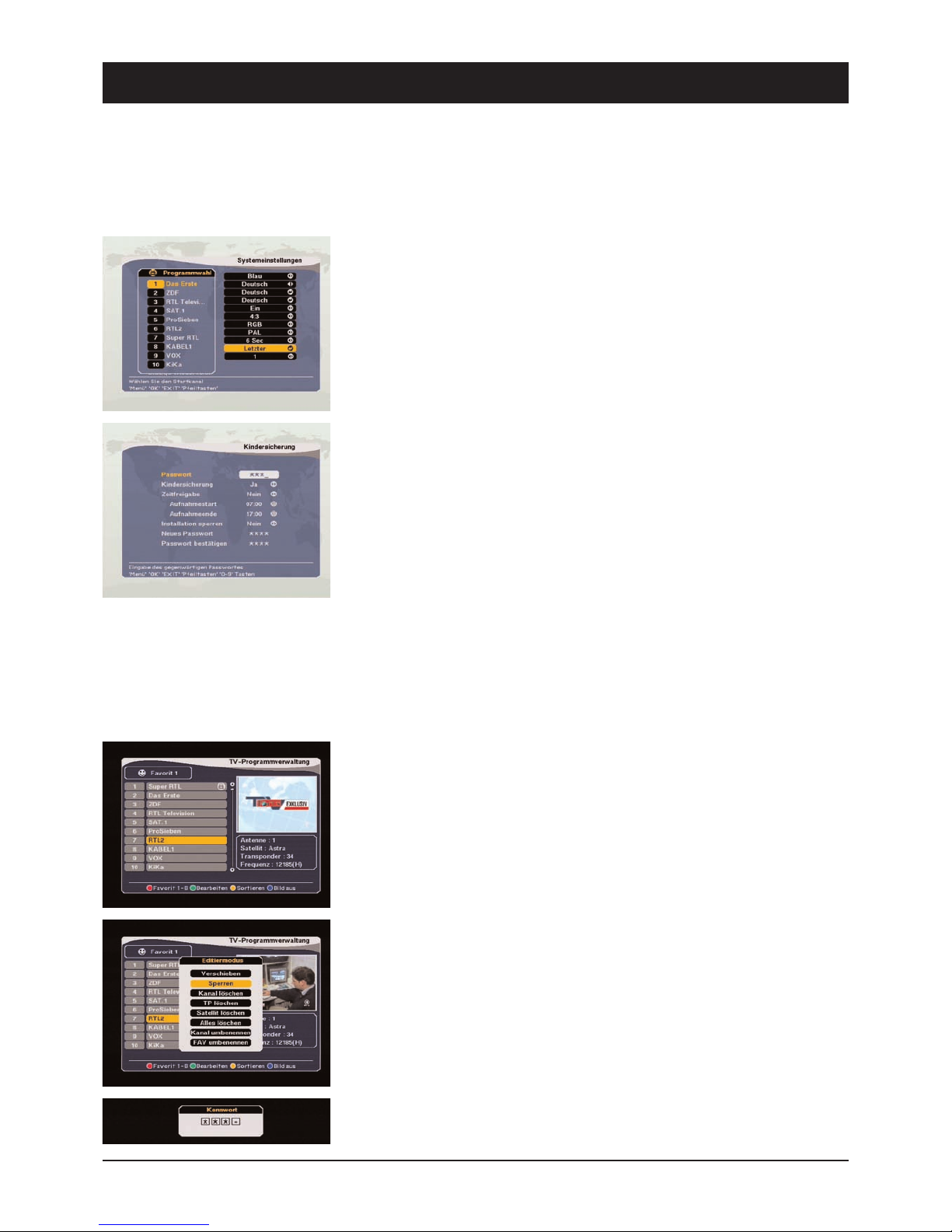
Start Channel: Press OK to open a channel list. Select the channel which should
always appear first after switching on the receiver. In the presetting the last viewed
channel always appears first after switching on the receiver.
9.4 Parental Control/Channel Lock
Channels which are not suitable for minors can be password-protected. It is also
possible to protect the installation menu and your personal settings against
unauthorised access.
Parental control consists of two parts: Specific channel blocking and specific menu
blocking, thus preventing access to undesired images.
In the parental control menu it is possible to set basic requirements, e.g. the
password, temporal (time and date) releases and blocking areas.
Changing the Password:
1) Enter the current password
2) Set “Parental Control” to ON
3) Enter a new password
4) Re-enter the new password to confirm the change
Note: The factory-set password is 0000.
Caution: Make a note of the new password and keep it in a safe place.
Using Parental Control:
5) Once the parental control function has been activated, open the channel
manager menu.
6) Press the green button (“Process”) and select “Lock”.
7) Select the channel to be locked.
8) Press OK. Locking is indicated by a lock symbol.
9) Exit the menu and switch off the receiver.
Note: To activate parental control, switch the receiver off and on again. After
58
9. Installation/Settings
39740
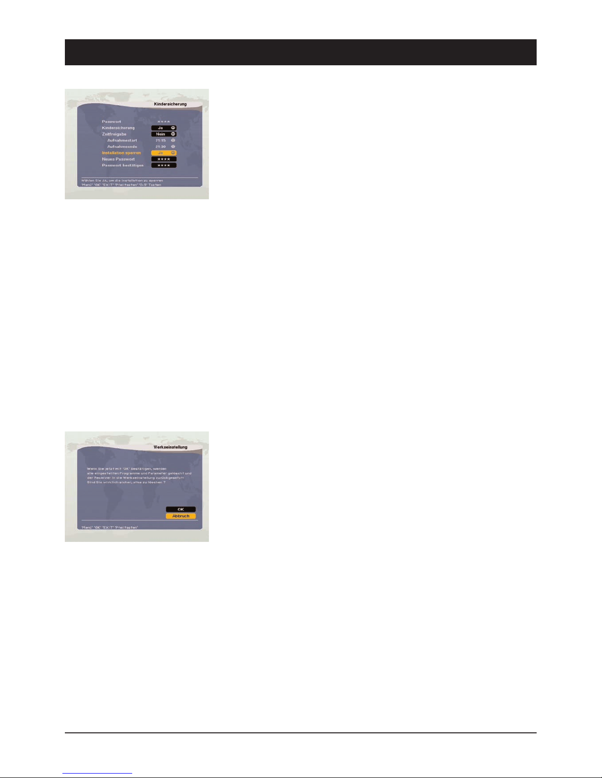
Installation Lock
Settings to prevent unauthorised access
1. Enter the password
2. Go to “Installation Lock” and select “Yes”
3. If necessary, enter a new password
4. Re-enter the new password thus confirming it
5. Close the menu and switch off the receiver
6. Switch on the receiver and press MENU
7. Select a menu and press OK
8. A password input request should appear on the screen
9. If the password is incorrect, it is not possible to access most of the menus
Note: The factory-set password is 0000.
Caution: Make a note of the new password and keep it in a safe place.
Temporal Release
If you wish to release channel and installation menu blocking at certain times of
the day, it is possible to define a time domain. All the channels as well as menus
with the exception of the “Parental Control” menu can be opened during these set
periods.
Caution: Please note that during these periods changes can also be carried out in
the “Channel Manager” menu, i.e. other locks can be changed.
9.5 Factory Setting
It is possible to reset the device to the delivery status. After confirming the device
reset, all the settings which have been carried out after initial start-up are deleted.
59
10. Daily Use: SAT TV and SAT Radio
39740
The most important basic functions and on-screen displays (OSD) are described in
detail below.
Whilst watching TV or listening to the radio, it is possible to open the respective
programme information on screen via INFO. The content and scope of this
information is made available by the channel operator.
The following instructions will help you to become familiar with even more useful
receiver functions.
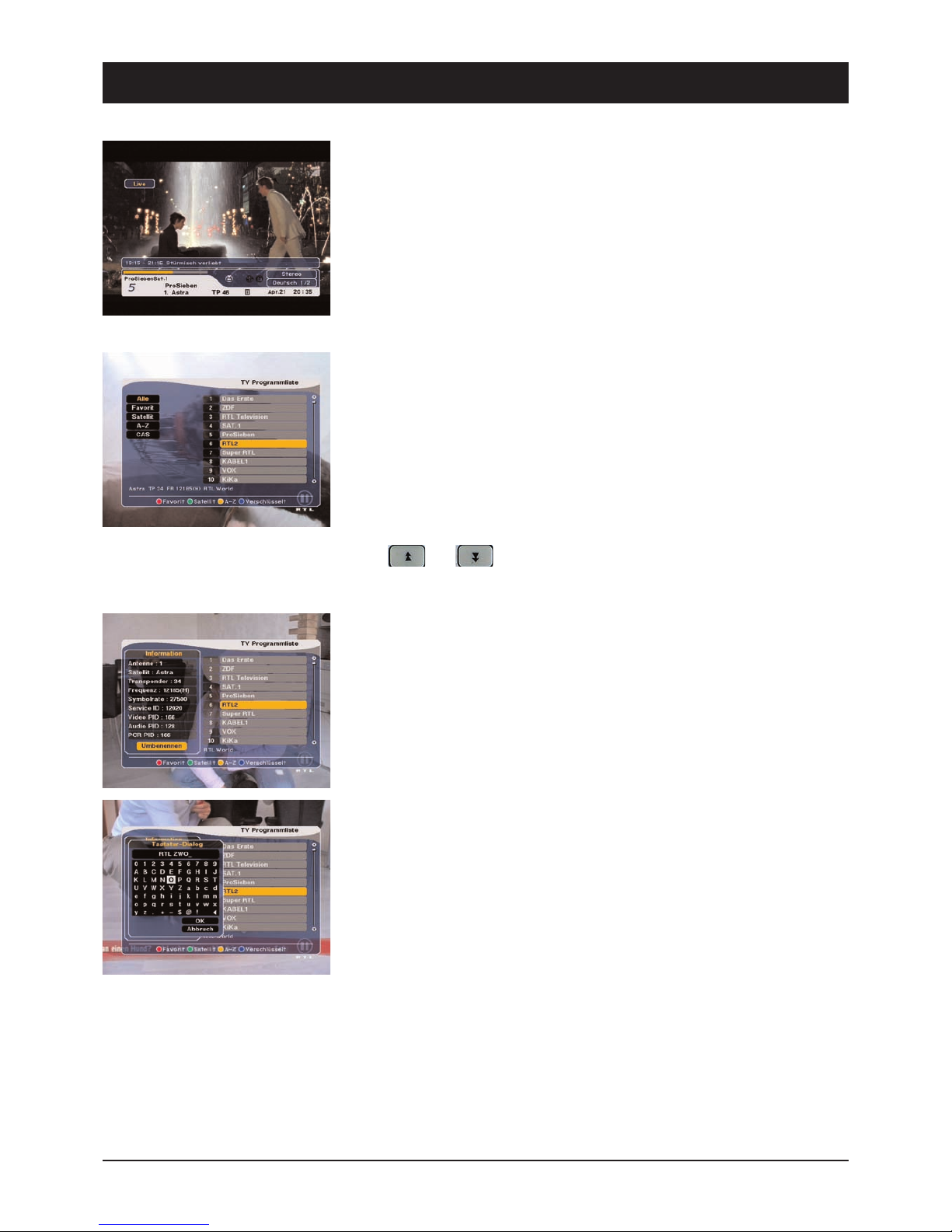
Select Channel:
There are several possibilities for channel selection. Use either the CH buttons on
the front of the receiver or PR-/PR+ on the remote control to switch channels
(upwards/downwards). In addition to the aforesaid functions there is also (for the
majority of channels which can be received) a more practical channel-selection
function: Whilst watching/listening to a programme, you can open a channel list via
OK. This can be closed again by pressing EXIT.
Select the desired channel from this list via PR+ and PR- and change to it by
pressing OK.
Since the channel lists usually contain several hundred channels, it is also possible
to use and to quickly leaf through the channel list.
Press INFO to receive detailed information about a channel's reception parameters
and the possibility to rename the channel. Press OK to rename a channel.
Use the on-screen keyboard to rename a channel.
Keyboard navigation occurs via PR+, PR-, E and W. Press OK to select a letter. In
order to save the settings, navigate over “OK” and press the OK button.

60
10. Daily Use: SAT TV and SAT Radio
39740
It is also possible to select which channel should be shown:
Favourites: Select one of 8 favourite lists (Note: If the favourite lists are empty, no
channels are listed!).
Satellite: Only the channels of the selected satellite are listed.
A-Z: Select the first letter of the desired channel.
All: Lists all the stored channels in one list.
Note: Once a channel list has been opened via OK, press FAV to accept the selected
channel in the favourite list (or to delete it). See page 23 and 24 for further
information.
TV/Radio Mode:
Whilst watching TV, it is possible to change to radio mode by pressing TV/RADIO.
Press the button again to return to TV mode.
Channel Jump:
Use <-PR to jump back to the previous programme position.
TV/AV Mode:
Whilst watching a SAT channel, it is possible to change to the AV mode (VCR) by
pressing TV/AV. The image of the device connected to the VCR socket (e.g. VCR or
SAT receiver) subsequently appears on the screen. Press the button again to return
to the SAT-TV mode.
Note: The LED on the front panel displays the current mode.
Channel Information:
Information about the current channel appears for 6 seconds after switching
channels. This information can be opened or closed at any time by pressing INFO
and EXIT respectively.
Pause Function:
PAUSE enables you to “freeze” the displayed TV picture. Press this button again to
exit this frozen-image and to return to the normal TV picture.
This manual suits for next models
1
Table of contents
Other Sky Master Receiver manuals

Sky Master
Sky Master DX 7 User manual

Sky Master
Sky Master DXH 90 User manual

Sky Master
Sky Master DXR 8000 User manual

Sky Master
Sky Master DVR 9600 User manual

Sky Master
Sky Master DVR 9200 User manual

Sky Master
Sky Master DXS 23 User manual

Sky Master
Sky Master DCI 9210 User manual

Sky Master
Sky Master DS 66 User manual

Sky Master
Sky Master DCI 9410 User manual

Sky Master
Sky Master DCX 10 CI User manual


