NITTOH Power UP-35DX-IN User manual

ELECTRIC/HYDRAULIC PUMPS
UP-35DX-IN(L)
Operation and maintenance manual
NITTOH ZOHKI CO.,LTD.
102,4-10,2-Chome,Kamezawa,Sumida-ku,
Tokyo 130,Japan
Telephone.03-3625-6551
Facsimile. 03-3625-6553

1
INDEX
page
1
Safety information------------------------
2
2
Description of components-------------
4
3
Instructions before use------------------
4
4
Operation-----------------------------------
5
5
Maintenance-------------------------------
5
6
How to remove the cover---------------
9
7
Circuits--------------------------------------
10
8
Construction drawings-------------------
11
9
Parts lists-----------------------------------
12
10
Trouble shooting guide------------------
13
11
Warranty------------------------------------
14

2
1Safety Information
Three types of symbols are used in this instruction manual to ensure correct use of the
product and to prevent harm to you or others or damage to property. The symbols and their
meanings are as follows. Please read the text after understanding the contents carefully.
NITTOH ZOHKI is not responsible for any damage or injury resulting from unsafe use of the
product, lack of maintenance, or improper application of the system.
Cautions remarks used in this manual are classified as follows;
⚠DANGER
If this symbol is ignored and the product is handled improperly,
there is a high probability that the user will be killed or seriously
injured.
⚠WARNING
Indicates a potentially hazardous situation which, if not avoided,
could result in death or serious injury to the user.
⚠CAUTION
Indicates a potentially hazardous situation which, if not avoided,
could result in injury to the user or property damage.
Cautions when installed
⚠WARNING
■Install the unit stably.
Since this pump uses a sealed tank, it can be used in all directions (diagonal, upside down,
vertical, horizontal), but please do not place it on an unstable surface. However, do not place
it on an unstable surface, as it may fall and cause injury. When installing the product at an
angle, make sure to fix it firmly.
■Prepare the work environment.
Remove any objects (high temperature, fire, movable objects, sharp objects, corrosive
objects, etc.) around the work area where the pump is used that may cause injury or harm
to the user.
⚠CAUTION
■Avoid rain and moisture, and use the product in a place with as little dust as possible.
■Avoid direct sunlight in summer. The temperature of the hydraulic fluid may rise, causing
problems with processing and equipment.
■For outdoor use in extremely cold weather, replace with hydraulic fluid of the proper
viscosity. The viscosity of hydraulic fluid increases as the temperature of the fluid drops,
which may cause problems with processing and equipment.

3
Precautions for use
⚠WARNING
■Take safety measures.
Use protective equipment, work clothes, safety glasses, etc. to protect yourself when
operating hydraulic equipment.
■Pay attention to the allowable pressure of the hydraulic circuit.
Always work to ensure that the maximum permissible working pressure of the pump is
less than the permissible pressure of other hydraulic equipment connected to it and less
than the permissible load.
■Be careful of electric shock.
Do not pull out the power plug with wet hands. Always use the grounding clip on the power
plug to ground the unit when in use. Do not use this product near an electric welding
machine or on grounded materials or equipment.
⚠CAUTION
■The power supply is AC200-230V 50/60Hz single phase.
Use of the wrong voltage may cause burnout or heat generation.
Use of the product at a low voltage may result in burning or overheating. Be careful of
voltage drops, especially when using a generator.
■When unplugging the power plug from the outlet, be sure to grab the power plug and pull
it out. Pulling the cord and unplugging it from the outlet may cause disconnection or short
circuit.
■When using auxiliary cords, please use 1.25 ㎟or more thick cords so that the voltage will
not drop, and the length should be within 10m.
Specifications
Model,No
Electric motor
Hydraulic pump
Reservoir
Weight
UP-35DX
-IN (L)
Commutator
and open type,
0.35KW
200-230V
50/60Hz
single phase,
“E”insulation,
2000rpm
Max,
Work pressure
MPa
Flow Rate
L/min(50Hz)
Capacity
1.0L
(2.0L)
Usable
0.8L
(1.6L)
1L
10.5Kg
2L
(12Kg)
1st stage
2nd
stage
1st stage
2nd
stage
1
70
2.5
0.3
4
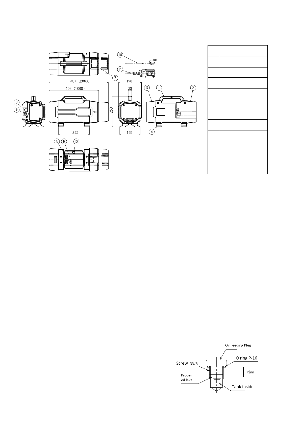
2 Description of components
3Instructions before use
3-1 Please make sure that there is no damage or oil leakage during transportation.
3-2 ⚠CAUTION Oil feeding plug
The tank (using a rubber tank) is a sealed type, so please use a sealed fueling plug. Also, be
sure to use a coupler with a check valve.
3-3 ⚠WARNING Check the power supply
The power supply is AC200-230V (50/60Hz) single phase. Be sure to ground the unit when
using it.
3-4 ⚠WARNING Check the hydraulic oil
To check the oil level, use the following method.
Always check the amount of oil in the pump with the cylinder of the connected equipment
fully returned before operation, and always use the correct amount. If oil is supplied when
the cylinder lot of the connected equipment is out, there will be no place for the oil in the
cylinder to return, and the oil will overflow, or high pressure will be generated in the tank,
which is dangerous.
(1) Turn the cylinders of the connected devices back on completely.
(2) Unplug the power supply.
(3) Stand the pump upright with the oil tank side
down.
(4) Turn the oil feeding plug with a flat-blade
screwdriver in the semi-clockwise direction to remove
it.
(5) Check the amount of oil from the removed oil
supply port.
1
Pump body
2
Back Cover
3
Tank Cover
4
Pump Feet
5
Relief Valve
6
Air Relief Valve
7
Storage Box
8
Oil Feeding Plug
9
Discharge Port
10
Power Cord
11
Operation Cord
12
Fuse

5
(6) If the oil fills up to the step in the oil supply cap, it is normal. (For the type of hydraulic
fluid to be used, refer to the section 5-1) Hydraulic fluid.)
(7) Turn the oil supply plug clockwise to tighten it. Be careful not to damage the O-ring.
4Operation
“UP-35DX-IN(L)”with 2-way normally closed solenoid valve, pressure holding and
inching type.
1. When you press the ON button on the two-point control switch, the motor turns and
oil is sent through the hose to the cylinder. When you release the switch button, the
motor stops, the oil stops flowing, and the cylinder stops.
2. When you press the OFF button on the two-point control switch, the solenoid valve is
activated and the oil in the cylinder returns to the tank. (The cylinder returns only
when the OFF control switch is pressed, and stops returning when the switch is
released. (An intermediate stop of return is possible.)
5Maintenance
5-1 Hydraulic oil
①Type of oil
As a general rule, use genuine oil NHO-32 (1 liter ). For urgent use, use high quality
hydraulic oil (equivalent to ISO standard #32 viscosity : 32 cSt @40℃).
②Oil temperature
The proper operating temperature for hydraulic fluid is 55℃or less. Stop working until
the temperature drops to the proper level.
③Oil change
⚠CAUTION
Since hydraulic fluid deteriorates, replace the entire amount periodically. The oil should
be replaced after 300 hours of operation or 3 months. To replace the oil, remove the oil
plug, turn the pump at an angle to remove the oil, and fill the pump to the top of the oil
plug, taking care not to let any impurities such as dust enter. The following are the
three points to keep in mind when replacing.
*Make sure that the cylinder is completely back in place.
*Never add different kinds of oil, even if it is only a small amount.
*When refilling the oil, be careful not to mix in any foreign matter.
④Other
⚠WARNING
If oil gets into your eyes, rinse thoroughly with clean water. Rinse thoroughly with
clean water and seek medical attention immediately. If oil gets into wounds or other
skin areas, rinse with soapy water, stop bleeding, and seek medical attention
immediately.

6
5-2 Pressure and piping
①Composition of hydraulic equipment system ⚠WARNING
When combining pumps, high-pressure hoses, cylinders, couplers, valves, etc. to form a
hydraulic system, make sure that the maximum working pressure of each device is the same.
If a pump with a lower maximum working pressure is used, the maximum working pressure
of the system should be adjusted to the lowest one.
②Pressure gauges
Install a pressure gauge to check the pressure at all times, or make it readily available.
③Piping ⚠CAUTION
Wrap sealing tape around the tapered pipe screw when connecting it to the hose piping or
to various valves and couplers. Refer to the taper screw tightening torque table below and
be careful not to over-tighten.
NPT,PT sizes
Tightening torque N-m(kgf-m)
1/8”
13-14 (1.3-1.4)
1/4”
30-40 (3.0-4.0)
3/8”
60-70 (6.0-7.0)
1/2”
100-110 (10.0-11.0)
Do not allow any scraps of sealing tape to enter the hydraulic equipment. Failure to do so
may result in damage.
5-3 High pressure hoses
①Hose installation ⚠WARNING
The high pressure hose will expand and contract slightly when pressurized, so allow
some room for expansion. Also, be careful not to rub against other hard objects.
Do not clamp the high pressure hose. The high pressure hose will stiffen and move to
straighten when pressure is applied. Clamping the hose, especially at the bent part,
may cause damage due to excessive force during pressurization. If the high-pressure
hose is not handled properly, its life will be extremely short. In particular, it is
susceptible to fire (high temperature), extreme bending, and twisting, so do not use it in
high temperature environments, below the minimum bending radius, or while twisted.
②Hose handling ⚠DANGER
Never drop objects into the high pressure hose. The impact of falling objects may cause
the high pressure hose to burst, resulting in a serious accident.
Do not pull the high pressure hose with strong force. Dragging or carrying the pump,
cylinder, etc. with the high pressure hose may cause damage to the high pressure hose,
resulting in a serious accident.

7
5-4 Coupler
①Connection
Before connecting the coupler, make sure that there is no dust, sand, etc. attached to
the connection part of the coupler. After connecting, pull the high-pressure hose to
confirm the connection.
②Handling ⚠WARNING
Do not pressurize the product with the coupler attached to the end of the
high-pressure hose without installing the cylinder. If the coupler is damaged, a
serious accident may result. If it is necessary to remove the coupler to check the
operation and pressurize, avoid working in a direction where the coupler may pop out.
Do not connect or disconnect the coupler while it is pressurized.
5-5 Air inclusion ⚠CAUTION
The UP-35DX series has a sealed structure with a rubber tank inside the tank cover.
When the tank is full of oil, there is no air ingress, but when a hose, cylinder, or other
pressure equipment is connected, the air in the hose, cylinder, or other equipment may
enter the pump. If air is mixed in the pump, the pressure will not rise, oil will not be
discharged, and other problems will occur. In this case, follow the procedure below to
restore the pump.
①Is the oil filled to the fullest level ?
Turn the pump upright (tank cover side down), open the oil supply valve, check the
amount of oil, and refill the tank to the full level. (For precautions, refer to "5-1) Replacing
the hydraulic fluid (3)".
②If the pump does not discharge or the pressure does not rise even after refilling with oil,
press the operation switch and the return switch about 10 to 11 times repeatedly with the
pump in the upright position.
③If the discharge or pressure still does not increase, loosen the air release valve (No. 5 on
page 3) at the bottom of the pump by about two turns, and press the operation switch and
the return switch repeatedly about 10 to 11 times. After that, tighten the air release valve
and operate the pump for confirmation.
④When the pump operates normally, be sure to refill the tank with oil to the full capacity.
This is because air in the hoses, cylinders, and other hydraulic equipment is in the tank of
the pump.
◎How does air accumulate in the pump (rubber tank) when hydraulic equipment is
connected together? Always make sure that the oil tank is full before use.
8
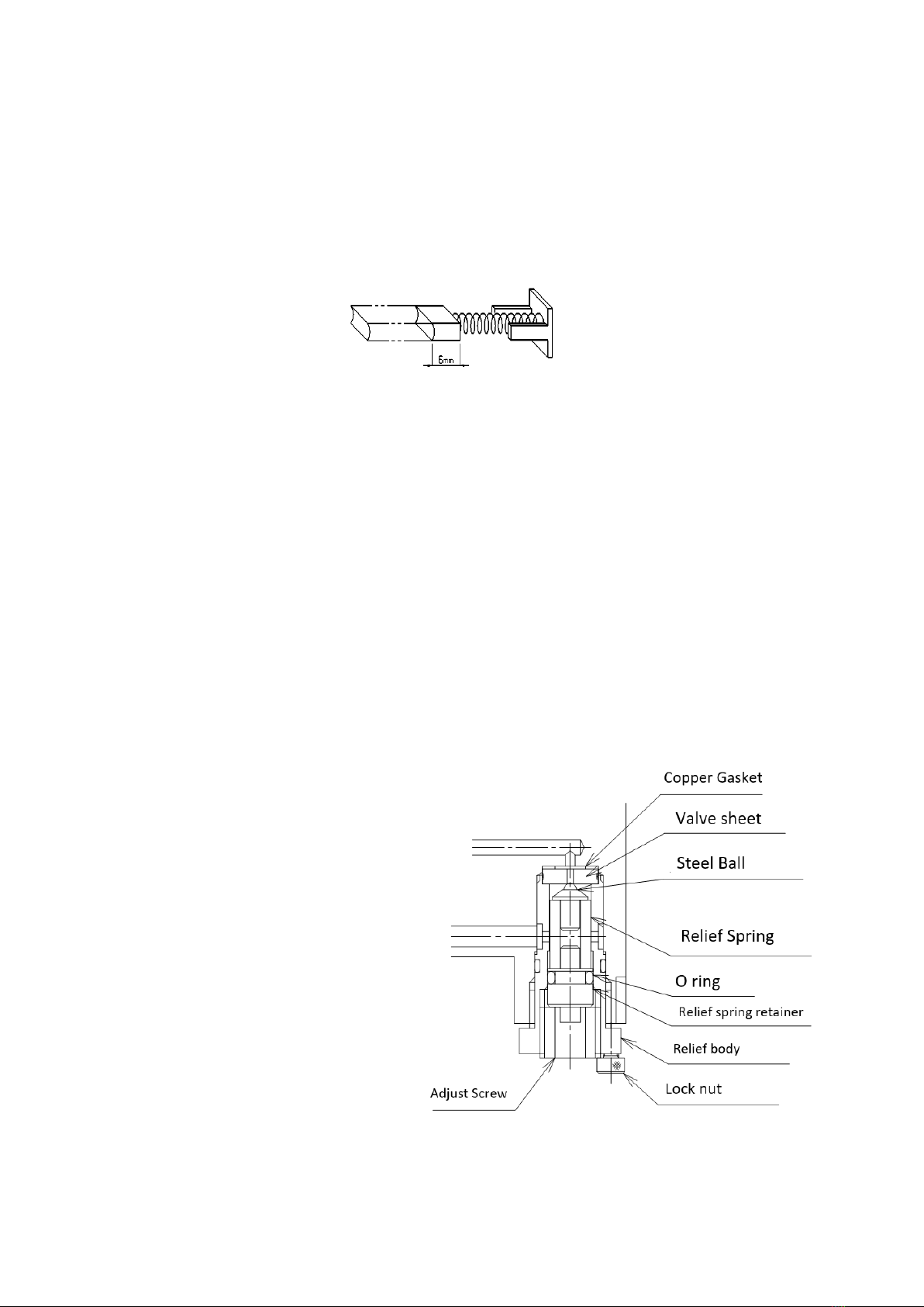
5-6 Carbon brushes
①Cautions for use ⚠WARNING
Always pay attention to the wear of the carbon brushes. When the carbon brush is worn
down to 6mm or when the motor has been running for more than 150 hours, replace it with a
new one. If worn brushes are used as they are, rectifying sparks will increase and cause
failure. The material of the carbon brush has a great influence on the performance and life of
the motor, so be sure to use a genuine carbon brush when replacing it.
①How to change
First, turn off the power; remove the two rubber caps, then loosen and remove the mounting
screws inside with a screwdriver to remove the carbon brush. Replace the brush with a new
one and fix the screws and rubber cap.
5-7 Relief valve adjustment
①Range of standard pressure adjustment available is form 58.8 to 68.6MPa. Loosen lock
screw on the high-pressure relief valve and turn the adjusting screw a few turns
counter-clockwise to decrease pressure setting to a lower desired pressure. Clockwise
rotation of the adjusting screw will increase pressure. After setting pressure, replace the
lock screw.
Different kind of a spring is needed to adjust and set at lower pressure than the standard.
Consult NITTOH authorized distributor.
Loosen the relief valve lock nut
(hexagon 2.5mm) and turn the adjust
screw (hexagon 6mm) to adjust the
pressure to the set value. Turning
the adjustment screw to the right
will increase the pressure, and
turning it to the left will decrease the
pressure.
However, the standard product can
be adjusted in the pressure range of
58.8 to 68.6 Mpa (600 to 700 kg/cm2).
If you want to use it at a pressure
lower than that, you will need to
replace the spring, so please contact
us.
Check the operation and tighten the
lock bolt. The pressure may change when the lock bolt is tightened, so please check the
set pressure again.
9
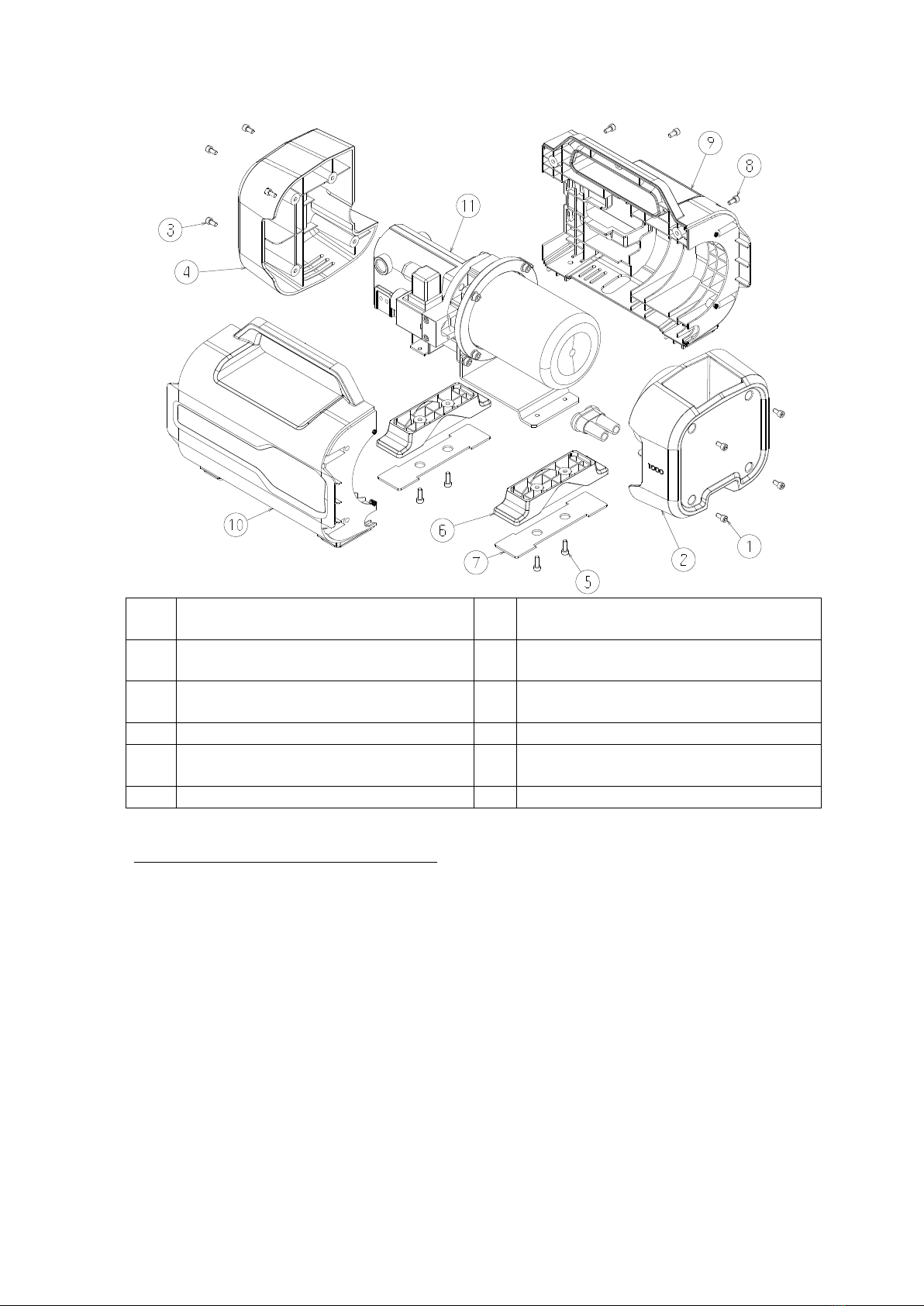
5-7 How to remove the cover
①
Fitting bolt M5×10 Hexagon socket
head screw
⑦
Rubber sheet
②
Tank Cover
⑧
Fitting bolt M5×10 Hexagon socket
head screw
③
Fitting bolt M5×10 Hexagon socket
head screw
⑨
Side cover 1
④
Back Cover
⑩
Side Cover 2
⑤
Fitting bolt M5×15 Hexagon socket
head screw
⑪
Pump body
⑥
Pump Feet
Disassembly procedure of the cover
The cover cannot be removed if the hose etc. are connected to the outlet.
1. Remove the 4 fitting bolts ①and ③, and then remove ②tank cover , and ④back
cover.
2. Lay the pump down so that ⑨the side cover 1 is on top.
3. Remove ⑤the fitting bolts, and remove ⑥the two pump feet. ⑦Rubber sheet
is glued.
4. Remove ⑧the 3 mounting bolts.
5. Lift up and remove ⑨the side cover 1.
6. Lift up and remove ⑪the pump body.
Note that there are some wires connected to the pump.
For installation, reverse the above procedure, paying attention to the pump alignment
and wiring.

10
6Circuits
Hydraulic Circuit
Electrical diagram
How to change the carbon brush
Relief valve & Air relief valve
1. Remove the back cover.
2. Remove the carbon
brush mounting screw
with a screwdriver.
3.Pull out the carbon
brush and insert a new
carbon brush.
4. Use the screw threads to
set it so that it is stuck in
the back.
5. Screw in the carbon brush mounting screw. If there is any
uncomfortable feeling when screwing in, do not screw it in but
remove it again. There is a possibility that the metal part of the
carbon brush will be deformed.
Lock screw
Relief Valve
Air Relief Valve

11
7 Construction drawings

12
8 Parts list
No.
Part No.
Description
Driving section
1-1
Base plate
1-2
AC0598A00
Oil seal
1-3
TLA1512Z
Bearing
1-4
Eccentric collar
1-5
RNAF273013
Bearing
1-6
φ4×28
Spring Pin
1-7
NTB1528
Thrust bearing
1-8
AS1528
Thrust Washer
1-9
Shaft
1-10
Second gear
1-11
Key
1-12
G-15
G ring
1-13
AS1528
Motor
1-14
M6×20CAP
Fitting bolt 1
1-15
PCB M6×15
Fitting bolt 2
1-16
M6
Washer
1-17
PT1/16
Plug
1-18
φ6
Steel ball
1-19
M8×6
Hollow set
1-20
MB700-050
Expander
1-21
MB700-040
Expander
Pump section
2-1
High pressure piston
2-2
Piston spring
2-3
Low pressure piston
2-4
Piston spring
2-5
Cupper packing
2-6
High pressure plug
2-7
Pushing screw
2-8
High pressure suction spring
2-9
φ6
Steel ball
2-10
Valve sheet
2-11
Pushing valve sheet
2-12
MSW12
Pushing screw
2-13
Valve sheet
2-14
φ5
Steel ball
2-15
WF5-10
High pressure check spring
2-16
Check retainer
2-17
P-7
O ring
2-18
P-7 bias
Back up ring
2-19
Low pressure suction holder
2-20
WF5-10
Low pressure suction spring
2-21
φ5
Steel ball
2-22
Valve sheet
2-23
Cupper packing
2-24
Suction retainer
2-25
MSW12-6
Pushing screw
2-26
MSWA20
Pushing screw
2-27
WF5-10
Low pressure check spring
2-28
φ5
Steel ball
2-29
Cupper packing
2-30
Retainer F
2-31
MSWAS12-6
Pushing screw
2-32
Low pressure suction filter
2-33
High pressure suction filter
Returning section
3-1
NW-22B
Solenoid
3-2
Base block
3-3
M5×45
Fitting bolt
3-4
M5
Spring washer
3-5
Push pin
3-6
φ3×8
Spring pin
3-7
Lever
3-8
MS3-25
Straight Pin
3-9
Lever support
3-10
M4×10 CAP
Fitting bolt
3-11
M4
Spring washer
3-12
Poppet
3-13
Sleeve
3-14
P-8
O ring
3-15
P-8 bias
Back up ring
3-16
P-5
O ring
3-17
P-5 bias
Back up ring
3-18
WH8-20
Spring
3-19
Valve sheet
3-20
P-9
O ring
3-21
P-9 bias
Back up ring
3-22
Valve sheet pushing screw
3-23
M4
Washer
3-24
M4.5×P0.75
Hexagon nut
3-25
M4
Tooth lock washer
3-26
-
-
3-27
-
-
3-28
-
-
3-29
Push pin holder
3-30
φ3×15.8
Push pin
3-31
Push pin spacer
3-32
P-3
O ring
3-33
P-3 endless
Back up ring
3-34
Stopper pin
3-35
WB6-10
Spring
3-36
MB700-040
Expander
3-37
P-5
O ring
3-38
M5×30
Fitting bolt
3-39
M5
Spring washer
Relief valve section
4-1
Cupper packing
4-2
Valve sheet
4-3
High pressure relief
4-4
S-12
O ring
4-5
φ2.5
Steel ball
4-6
Relief ball receiver
4-7
High pressure spring
4-8
Spring pushing
4-9
P-6
O ring
4-10
MSWA12
Pushing screw

13
4-11
M3×6
Lock screw
4-12
φ6
Steel ball
4-13
Ball pushing
4-14
P-4
O ring
Tank section
5-1
Rubber tank 1L
5-2
Fixed tank ring
5-3
M6×20
Fitting bolt
5-4
M6
Spring washer
5-5
Oil feeding plug
5-6
P-16
O ring
5-7
Discharge nipple
5-8
TSC-14
Coin filter
5-9
O-14
Snap ring
5-10
Pump stay tank side
5-11
M6×10
Fitting bolt
5-12
Pump stay motor side
5-13
M4×10
Firring bolt
9 Trouble shooting guide
⚠WARNING To avoid injury, repairs and troubleshooting should be performed
by qualified personnel familiar with this type of equipment. Use appropriate gauges and
equipment.
Problems
Possible Causes
Remedies
Motor does not run
⚠WARNING
Disconnect power
supply before
disassembly or repair.
(1) No supply voltage.
(2) Broken lead wire or defective
power cord plug.
(3) Defective switches.
(4) Worn carbon brushes.
(5) Defective motor.
(6) Defective remote switch.
(7) Unit is not plugged in.
(1)Check line voltage.
(2)Replace defective part.
(3)Check switches.
(4)Replace carbon brushes.
(5)Repair or replace motor.
(6)Repair or replace switch.
(7)Plug in unit.
Abnormal noise of
motor.
(1)Damage or pump or motor.
(2)Damage of ball bearings, etc.
(1) Repair or replace unit.
(2) Replace ball bearings.
Motor runs, but
cylinders do not
advance or retract.
(1)Damage of release valve.
(2)Oil level is too low.
(3)Air in system.
(4)Filter plugged or dirt in pump.
(5)Damage of pump body.
(6)Damage or out of adjustment
of relief valve.
(1) Repair or replace it.
(2) Fill reservoir to 1/2 of level
gauge with all cylinders
retracted.
(3) Bleed the system.
(4) Pump filter should be
cleaned and if necessary,
pump should be dismantled
and cleaned.
(5) Repair pump.
(6) Repair or readjust as needed.
Cylinders works, but
full pressure is not
built up.
(1) Damage of release valve.
(2) Air in system.
(3) Damage of pump body.
(4) Lowering of set pressure or
damage of relief valve.
(1)Repair or replace.
(2)Bleed the system.
(3)Repair pump.
(4)Readjustment of set pressure
or repair of relief valve.
Cylinders works, but
their speed too slow,
partially or erratically.
(1) Damage of release valve.
(2) Air in system.
(3) Unacceptable rise in oil
temperature.
(4) Damage of pump body.
(1)Repair or replace.
(2)Bleed the system.
(3)Stop operation or install oil
cooler. (max. 55℃)
(4)Repair pump.
Cylinders do not
retract.
(1) Damage of release valve.
(2) Damage of return springs of
cylinders or quick couplers.
(1) Repair or replace.
(2) Repair or replace springs or
couplers.
Oil leaks.
Damage seals, seats or steel
balls.
Replace them.
Short circuit.
(1)Damage cords.
(2)Bad insulation of electric
parts.
(1)Replace.
(2)Replace.

14
10 Warranty
10-1) Warranty period
For general defects and failures, 365 days from the last day of the month of
manufacture.
Example: If the pump was purchased on January 1, 2019, the warranty period will be
until January 31, 2020.
10-2) Warranty conditions
NITTOH products and components are warranted against damage to products and
components due to defects in materials and workmanship, with the following exceptions
This warranty provides for the repair and replacement of the product or component
parts at no charge. In the event of a malfunction within the warranty period, please
present this warranty card and contact your dealer or nearest Nittoh sales office.
10-3 Exceptions to the Warranty
Warranty claims will not be accepted for damage or malfunction caused by the following
reasons
Misuse or improper use, fair wear and tear, incorrect or careless operation, improper
storage, chemical or electrical effects, climatic or other effects that cannot be
specifically linked to manufacturing defects
We are not responsible for packing, springs, etc. and the following items.
Modification or processing of the product carried out by the purchaser without prior
notice or consent to us.
Harsh and very frequent use of the product deviating from its specifications.
Damage caused by incorrect installation or assembly by the purchaser or a third party.
Failure due to natural disasters.
Damage caused by fire, submersion, dropping, or other accidents.
This manual suits for next models
1
Table of contents
Other NITTOH Power Water Pump manuals

Popular Water Pump manuals by other brands

Blue-White
Blue-White Chem-Feed C-1100A operating manual

Ceco
Ceco Sethco 2500 Series Operation manual

MRC
MRC PP-D-720 Operation manual

ProMinent
ProMinent DULCO flex Control Original operating instructions

SPERONI
SPERONI HDM Series Operating instruction

Clarke
Clarke DWP400A Operation & maintenance instructions


