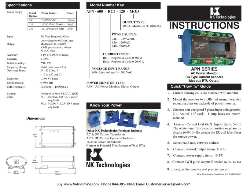
NK TECHNOLOGIES APN Series User manual

1. Ensure correct model was chosen for Current Input
Type: 5 amp or low-voltage 333mVAC.
2. Mount the monitor to a DIN rail using integrated
mounting clips on backside of power monitor.
3. Connect non-energized 3phase input voltage(term.
2-4,neutral 1if used). 1amp fusesare recommend-
ed. Tighten all terminals to 5-7 inch-pounds.
4. Connect Current Transformer Inputs (term. 5-10).
The white wire (or X1 terminal) from a CT is posi-
tive or phase indicator (6-8-10).
5. Select baud rate, network address
6. Connect network output (term. 11-13)
7. Connect power supply (term. 16-17)
8. Connect kWH pulse output if needed
9. Energize the monitor and primary circuit.
10. Set CT ratio and KWH type using buttons below
the display.
APN - 600 - MV - 120 - MOD
CURRENT INPUT:
5A - 5 amp secondary CT
MV - 0.333 VAC secondary (ProteCT)
VOLTAGE INPUT RANGE:
600 - Line voltage 100 - 600 VAC
POWER MONITOR TYPE:
APN - AC Power Monitor, Digital Output
Model Number KeySpecifications
Quick “How To” Guide
OUTPUT TYPE:
MOD - Modbus RTU (RS485)
POWER SUPPLY:
24U - 24VAC/DC
120 - 120VAC
240 - 240 VAC
3511 Charter Park Drive, San Jose, CA 95136
800-959-4014 or 408-871-7510 Phone
408-871-7515 FAX
Know Your Power
Other NK Technologies Products Include:
AC & DC Current Transducers
AC & DC Current Operated Switches
1φ& 3φ Power Transducers
Current & Potential Transformers (CTs & PTs)
Power Supply
Current Input 5 Amp secondary CT or
ProteCT (0.333VAC)
5A series: 50-3000A)
MV series: 5-1500A)
Voltage Input 347/600VAC 3-PhaseWye system
with earthed neutral, Measurement
Category III
600VAC 3-Phase Delta system,
Measurement Category III
Output Modbus RTU (RS485)
KWH pulse contact,
40mA and 50 VDC max.
Accuracy < 1%
Linearity < 0.5%
Isolation Voltage 2500 VAC
Frequency Range Auto. selects 50 or 60 hertz
Operating Temp. 14 - 122° F (-10º to +50° C)
Enclosure UL94 V0 Rated
Environmental 0–95% Relative Humidity non-
condensing
Altitude to 2000 meters
Pollution Degree 2
Indoor Use
EMC/Immunity EN50081-1, EN50082-2
Agency Approvals UL/cUL Listed
INSTRUCTIONS
APN SERIES
AC Power Monitor
Maximum 600 Volts
Modbus RTU Output
Model
Option Power Voltage Usage OVP Category
24U 24VAC/DC +/-10% (50-
60Hz AC power) 180mA II
120 120 VAC +/-10% 50-60Hz 50mA II
240 240VAC +/-10% 50-60Hz 25mA II

APN Power Monitors feature a 35mm wide DIN rail compatible
housing.Itshouldbe installedin aULlistedfire/electrical enclosure
certified under NRTL, or similar.
If the equipment is used in a manner not specified by Neilsen-
Kuljian, Inc., the protection provided by the equipment may be
impaired.
To mount on DIN rail: Orient transducer so that line voltage ter-
minals (1) neutral if used, (2) phase C, (3) phase B and (4) phaseA
are upright/at the top of unit and snap securely onto DIN rail.
To remove, pull the spring clipsaway from the rail onthe monitor underside,
on the left and right corners.
De-energize the monitored circuit. It is not recommended to
install the current sensors over an energized conductor. If unavoid-
able, adopt safe operating procedures when installing or removing
the current sensors.
Identify the monitored circuit phases asA, B and C, in no particu-
lar order. Connect the primary voltage using up to 10 AWG rated
75/90°C, to terminals 1-4,A to 4, B to 3, C to 2 and the neutral (if
used) to 1, and torque to 5-7 inch-pounds.Adding one amp fuses to
the voltage input leads will protect the power monitor. Equipment
can be used to monitor either Wye or Delta systems.
Install UL Listed Energy Monitoring Current Transformer (CT)
certified under category XOBAover each identified phase conduc-
tor. Connect CT secondary using 26-14 AWG wire (twisted pair
if ProteCT CT is used) Phase A to terminals 9-10, B to term. 7-8,
and C to term. 5-6. The CT terminal marked X1 or the white lead
connects to the positive and the black lead goes to negative. It is
essential that the phase relationships be matched. PhaseAvoltage
is connected to terminal 4, CT over phaseA connects to term. 9 &
10, and so on for all three phases as labeled.
The H1 side of the CT must face the source.
The output will not be correct if there are any mismatched
phases. Use a shorting block is highly recommended if 5 amp
secondary CTs are used.
The current sensors may not be installed in a panel where they
exceed 75% of the wiring space of any cross-sectional area of
the panel.
Separate Class 1 and non-Class 1 conductors per NEC.
Description
Installation
Input Wiring
APN Series Power Monitors are designed to monitorAC loads and
provide data points displaying line voltage, current, instantaneous
wattage, accumulated watt-hours and power factor. The APN is
available with a Modbus RTU (RS485) output as standard, and
also provides a configurable pulsed contact representing accumu-
lated watt hours.
Power Supply Wiring Connection
Connect correct power supply voltage to terminals 14 & 15 on
transducer using 22-14AWG copper wires rated 75/90°C and
tighten terminals to 5-7inch-pounds torque. Use 20Abranchcircuit
protection against the remote possibility of a short.
Modbus Address and Baud Rate
1 2 3 4 5 6 7 8
ADD VALUES
1 2 4 8 16 32 64 128
Edge of board
The node address is
set through a series
of eight dip-switches
allowing a possible
address range of1-247.
After converting your
decimal address to bi-
nary either by hand or
with a calculator you can set the dip-switches by flicking the
operating lever toward the edge of the board. As an example,
the illustration above shows the address set at the decimal
value of 23. Switch 1=1, 2=2, 3=4, 5=16. 1+2+4+16=23
Note that switch 8 has the largest value.
Cycle power to the unit after changing the network address.
The baud rate can be set for 9600 or 19200 bps by placing
the switch to the left of the node address block, in the ap-
propriate position.
9600
19200
Power
Supply Baud
Rate Network
Address KWh
Pulse
Modbus
Output
Programming
Buttons
LCDDisplay
4linesof20characters
Primary Voltage Inputs
A
B
CN
If Used
Current Transformer
Inputs
A
B
C
+ -
+ -
NKTech APN Monitor
v.1.00 3ph4W
Set Up Screens
When the field input connections have been made (current
transformers and voltage), and the monitor is powered up,
the LCD will display the following screen:
Product series, firmware version,
and meter configuration (three
phase, four wire).
After approximately two seconds, the display will show the
default data display screen:
Volts Amps Watts
128.8 27.5 2871
129.7 28.5 2997
127.8 27.5 2749
Voltage and current are RMS values, the watts displayed are
active power. The measurement is made with six, twenty four bit
analog to digital converters.
Press one of the three buttons below the display and the
display will change to:
select:
Setup Display Press the button below “Set-Up” and
the display will change:
select:
pick store kwhr
CT kwhr pulse
Press the button below “Pick CT” to
program the CT range value. The dis-
play will show the available ranges for
the type of current sensors appropriate
for the device (ProteCT or 5amp secondary)
select:
333mVCTs
5A Next 15A
Press the button below the matching
value of the current transformers you
have installed. Press “Next” to advance
through the available CT ranges.
select: Save?
333mVCTs
No Yes 15A
Press the button below “yes” to save
the CT range value. Selecting “No”
will return you to the data display
screen.
Display is 4 lines of
20 characters max.
+ -
+ -
Yellow
LED,
flashes
with
kWH-
pulse

select:
pick storeKWHr
ct KWHr pulse
Enter KWHr setup by pressing the button
to either “Store KWHr” to save and display
the accumulated watt hour value to flash
memory or “KWHr Pulse” to save and dis-
play accumulated value only while powered
on. Any change to the meter set-up will clear
the KWHr pulse.
Pressing “KWHr Pulse” before “Store
KWHr” will clear any previously ac-
cumulated watt hour value from flash
memory.
5-Amp Secondary CT
Ranges 333mV Secondary CT
Ranges
50 600 5 250
75 800 15 300
100 1000 30 400
150 1200 50 600
200 1500 70 800
250 1600 100 1000
300 2000 150 1200
400 2500 200 1500
500 3000
The APN can be used with many current trans-
formers, and it must be programmed for the
range you will be using. The ranges available
are:
Next select the rate at which the pulse con-
tact opens and closes. The options are 1/10,
1, or 10 KWH per pulse. The solid state no
voltage contact will open and close when
the selected watt hours have accumulated.
Note: Only the 10KWHr setting is available
with CT ranges of 1000 or higher.
select: Save?
KWHr Yes NO
Once the pulse rate has been selected, the
display will change to show the selected
rate on the left. Pressing the button below
“Yes” will save this value to memory.
Pressing the button below “No” will return
you to the Power Up ID.
After completing the set up programming, the
LCD display can be changed to show several data
points. Press any button, and the display selection
screen will be seen.
select:
Energy PwrFtr VAWatt
Press the button below “Energy” and
the display will change to show the
following:
Energy
sumWatts 3,480
KWHr 127
PwrFtr +0.68
Sum Watts shows the active power
being used at any time.
KWHr increases as kilowatt hours are
accumulated.
Pwr Ftr shows the average power fac-
tor of all three phases.
This is generally the last screen viewed, and will be the default screen
shown. Press any button to return to set up or display other values.
select:
Energy PwrFtr VAWatt
Press the button below “PwrFtr” to
display the power factor of each phase
PowerFactor
A +0.70
B +0.71
C +0.68
The power factor is shown with a (+)
positive notation for inductive loads,
and a (-) notation for loads which are
capacitive.. If the monitored load is in-
ductive, all three phases should show
power factor as positive. If one or
more phases are displayed as “0.01”,
the current transformer is facing the
wrong direction or the leads are re-
versed (X1 connected to negative).
select:
Energy PwrFtr VAWatt
Press the button below “VAWatt” to
display the voltage, current and watts
of each phase.
Volts Amps Watts
128.8 27.5 2871
129.7 28.5 2997
127.8 27.5 2749
About MODBUS and the APN Power Monitor
MODBUS® Protocol is a messaging structure, widely
used to establish master-slave communication between
intelligent devices. A MODBUS message sent from a
master to a slave contains the address of the slave, the
‘command’(e.g. ‘read register’), the data, and a check
sum (CRC). Since MODBUS protocol is just a messag-
ing structure, it is independent of the underlying physical
layer. The interface used by the Monitor is RS-485.
The Query
The function code in the query tells the addressed slave
device what kind of action to perform. The data bytes
contains any additional information that the slave will
need to perform the function. Only function code 03 HEX
(Read Holding Registers) is supported by the Monitor,
other codes will not be responded to and the red FAULT
LED will turn on. The Monitor will read the requested
registers and return their values. The data field will con-
tain the information telling the slave which registers to
read. The error check field (CRC) provides a method for
the slave to validate the integrity of the message contents.
The Response
If the slave detects a transmission error, the message
will not be acted upon, but the red FAULT LED will be
turned on. If the slave makes a normal response, the func-
tion code in the response is an echo of the function code
in the query. The data bytes contain the data collected by
the slave, with the reading of voltage, current, Watts and
Power Factor.
If an out of bounds register is requested , no register
or too many registers have been requested, the function
code is modified by adding 80 HEX to the function code
(returning 83 HEX) to indicate that the response is an
error response. There also will be 2 data bytes of zeros
returned. The error check field (CRC) allows the master to
confirm that the message contents are valid.
RTU Mode
When controllers are setup to communicate on a MOD-
BUS network using Remote Terminal Unit (RTU) mode,
each eight-bit byte in a message contains two four-bit
hexadecimal characters. Each message is transmitted in a
continuous stream.
Coding System
Consists of eight-bit binary, hexadecimal 0 ... 9, A ... F.
There are two hexadecimal (HEX) characters contained in
each eight-bit field of the message
Bits per Byte:
1 start bit
select:
10/KWH next 1/KWH
Press the button below the value you have
selected, or next to see other values.
Pulse Contact Connection
DC Power Source
Out to Controller 10K Pull Up Resistor
Use an external resistor
of 10K ohm from the DC
power to the pulse output
contact (+) and out to the
controller input. Ground
the (-) terminal of the pulse
contact. This will allow volt-
age to pass when the output
is open, and block when
closed. One kwh value is
represented with an open and
closed output cycle.
-+

Table 1 Register Map - Read Only
CT size or
ratio Multiply
data by
5 to 15A 1 (direct
reading)
30 to 200A 10
250 to 2000A 100
2500, 3000A 1000
Table 2 Scaling For Watts
Data
About MODBUS and the Monitor (continued)
8 data bits, with the least significant bit sent first
1 bit for even parity
1 stop bit
Errors that occur during a query, such as parity or CRC,
will flash the FAULT LED and no response will be sent.
RTU Framing
In RTU mode, messages start with a silent interval of at
least 3.5 character times. This time is scaled to BAUD rate
with the BAUD selection switch.
The first field then transmitted is the device address. The
allowable characters transmitted for all fields are hexadeci-
mal 0 ... 9, A ... F. The Monitor monitors the network bus
continuously, including during the silent intervals. When
the first field (the address field) is
received, the Monitor decodes
it to find out if it matches the
address set on the switch. If there
is a match the following bytes
are collected. Following the last
transmitted character, a similar
interval of at least 3.5 character
times, marks the end of the mes-
sage. The Monitor will collect the
data and respond to the master. A
new message will begin after this
interval
Troubleshooting
1. No Data shown on LCD Display
Recheck that all connections are made properly, and the
power supply to the unit is energized. Recheck line volt
age fuses to be sure they are conducting.
2. Negative Power Factor when monitoring an induc-
tive load.
One or more current transformers are reversed, either
the marked H1 side is not facing the power source or the
output leads are reversed. The X1 secondary must be con-
nected to the positive input terminal.
3. Modbus output is not being received at the Master
Check the slave (APN) network address setting to be
sure there are no conflicts with other network nodes. Also
recheck the baud rate settings to match the other equip-
ment.
Address Register Type Description
0 40001 Integer, 16 bit Volts RMS Phase A
1 40002 Integer, 16 bit Current RMS PhaseA
2 40003 Integer, 16 bit Watts (active) Phase A
3 40004 Integer, 16 bit Volts RMS Phase B
4 40005 Integer, 16 bit Current RMS Phase B
5 40006 Integer, 16 bit Watts (active) Phase B
6 40007 Integer, 16 bit Volts RMS Phase C
7 40008 Integer, 16 bit Current RMS Phase C
8 40009 Integer, 16 bit Watts (active) Phase C
9 40010 Integer, 16 bit Watts (active) sum
10 40011 Integer, 16 bit Energy (active) KWH, MSB, (see Note 1)
11 40012 Integer, 16 bit Energy (active) KWH, LSB
12 40013 Integer, 16 bit Power Factor, Phase A (see Note 2)
13 40014 Integer, 16 bit Power Factor, Phase B (see Note 2)
14 40015 Integer, 16 bit Power Factor, Phase C (see Note 2)
Notes:
1. Energy is saved in two registers (40011 and 40012) for a maximum
total of 4,294,967,295 kWHr. To combine the two registers, multiply
MSB by 65,536 and add to LSB
2. A power factor reading of 70 = +0.70 (inductive). A power factor
reading of 198 = -0.70 (capacitive). If the data shows readings greater
than 128, subtract 128 from the reading and change the sign to nega-
tive. In the case shown as an example, 198 - 128 = 70, but the sign
should be changed to negative to represent a leading power factor.
Other NK TECHNOLOGIES Monitor manuals
