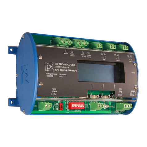
NK TECHNOLOGIES APN Series User manual

1. Current sensing coils are matched with monitor
2. Mount the monitor to a DIN rail using integrated
mounting clips on backside of power monitor.
3. Connect non-energized 3phase input voltage(term.
2-4, neutral 1 if used) . 1 amp fuses are recom-
mended.
4. Connect Current Coil (RC) Inputs (term. 5-10).
The white wire from a coil is positive or phase in-
dicator (6-8-10). Be certain the RC coil label faces
the source power.
5. Select baud rate, network address
6. Connect network output (term. 11-13)
7. Connect power supply (term. 16-17)
8. Connect kWH pulse output if needed (term. 14-15)
9. Energize the monitor and primary circuit.
APN - 600 - RC1 - 120 - MOD
CURRENT INPUT:
RC1- Rogowski Coils 0-500 A
RC2- Rogowski Coils 0-2000 A
VOLTAGE INPUT RANGE:
600 - Line voltage 0 - 600 VAC
POWER MONITOR TYPE:
APN - AC Power Monitor, Digital Output
Model Number KeySpecifications
Quick “How To” Guide
OUTPUT TYPE:
MOD - Modbus RTU (RS485)
POWER SUPPLY:
24U - 24VAC/DC
120 - 120VAC
240 - 240VAC
APN -RCInstruction Sheet Rev 4 5/15 P/N791000007
Know Your Power
Other NK Technologies Products Include:
AC & DC Current Transducers
AC & DC Current Operated Switches
1φ& 3φ Power Transducers
Current & Potential Transformers (CTs & PTs)
Power Supply
Input RC Type Rogowski Coils
Line voltage to 600VAC max.
Output Modbus RTU (RS485)
KWH pulse contact, 40mA
50VDC max.
Accuracy < 1% (10-100% of range)
Linearity < 0.5%
Isolation Voltage 2500 VAC
Frequency Range 50-60 hertz auto select
Operating Temp. 14 - 122 Deg. F
(-10 to +50 deg C)
Enclosure UL94 V0 Rated
Environmental 0–95% RH
EMC/Immunity EN50081-1, EN50082-2
Listings Designed to Meet UL/CUL &CE
Coils RC1 - 0-500 A, 3.25” ID 3 meter
long leads
RC2 - 0-2000 A, 5.25” ID 3 meter
long leads
INSTRUCTIONS
APN SERIES
AC Power Monitor
RC Type Current Sensors
Modbus RTU Output
Model
Option Power Voltage Usage
24U 21-27VAC/DC 180mA
120 100-125 VAC 50-60Hz 50mA
240 200-250VAC 50-60Hz 25mA
188.66mm
65.91mm
85.83mm
111mm
4.37 in.
2.6 in.
3.38 in. 7.43 in.
Dimensions

APN Power Monitors feature a 35mm wide DIN rail com-
patible enclosure and are typically located in the same
environment as motors, contactors, heaters, pull-boxes, and
other electrical enclosures.
To mount on DIN rail: Orient transducer so that linevoltage
terminals (1) neutral if used, (2) phase C, (3) phase B and
(4) phase A are upright/at the top of unit and snap securely
onto DIN rail.
After checking that the monitored circuit is off, identify
the monitored circuit phases asA, B and C, in no particular
order. Connect the primary voltage using up to 10AWG, to
terminals 1-4,Ato 4, B to 3, C to 2 and the neutral (if used)
to 1, and torque to 7 inch-pounds.Adding one amp fuses to
the voltage input leads will protect the power monitor.
Install Current Coil (RC) over each identified phase conduc-
tor. Connect RC secondary using provided three meter long
cable. Phase A to terminals 9-10, B to term. 7-8, and C to
term. 5-6. The RC white lead connects to the positive and
the black lead goes to negative. It is essential that the phase
relationships be matched. Phase A voltage is connected to
terminal 4, RC over phase A connects to term. 9 & 10., so
on for all three phases as labeled.
The label on the RC coil must face the source.
The output will not be correct if there are any mis-
matched phases. A shorting block is not required
Description
Installation
Input Wiring
APN Series Power Monitors are designed to monitor AC
loads and provide data points displaying line voltage, cur-
rent, instantaneous wattage, accumulated watt-hours and
power factor. The APN is available with a Modbus RTU
(RS485)outputasstandard,andalsoprovidesaconfigurable
pulsed contact representing accumulated watt hours.
Power Supply Wiring Connection
Connect correct power supply voltage to terminals 16 &
17on monitor using up to 14AWG copper wires and tighten
terminals to 5.3 inch-pounds torque.
Modbus Address and Baud Rate
1 2 3 4 5 6 7 8
ADD VALUES
1 2 4 8 16 32 64 128
Edge of board
The baud rate can be set for 9600 or 19200 bps by placing
the switch to the left of the node address block, in the ap-
propriate position.
9600
19200
Power
Supply Baud
Rate Network
Address KWh
Pulse
Modbus
Output
Programming Buttons
LCDDisplay
4linesof20
characters
Primary Voltage Inputs
A
B
CN
If Used
Current Transformer
InputsA
BC
+ -+ -
+ -
NK Tech APN \Monitor
v.1.00 3Ph 4W R
Set Up Screens
When the field input connections have been made (Rogowski coils and
line voltage), and the monitor is powered up, the LCD will display the
following screen:
Product series, firmware version, and meter configuration
(three phase, four wire). “R” refers to RC current inputs
1.After approximately two seconds, the display will show the defaultdata
display (VAWatt) screen.
Volts AMPS KWatts
128.8 27.5 2871
129.7 28.5 2997
127.8 27.5 2749
Voltage and current are RMS values, the watts displayed are active
power.
2. Press one of the three buttons below the display and the display will
change to:
select:
Setup Display
Press the button below “Set-Up” and the display will change:
select:
store KWHr
KWHr pulse
To remove, press upward on the tabs on
the monitor underside, on the left and right
corners.
3. Select “Store KWHr” to save the accumulated watt hour value to
flash memory. The count will be restored after a loss of power. Select
“KWHr Pulse” to save the counts to the Energy display only (lost is
power is interrupted). Select either to set the pulse interval for watt
hour counting. Pressing “KWHr Pulse” before “Store KWHr” will clear
any previously accumulated watt hour value from memory.
Yellow
LED,
flashes
with
kWH-
pulse
There are two LEDs under the cover between the network
connection terminal block and the pulse LED. The one on
the right (red) will light when there is a fault in the output,
and the one on the left (yellow) will flash to indicate net-
work data communication.
The node address is set
through a series of eight
dip-switches allowing a
possible address range of
1-247. After converting
your decimal address to
binary either by hand or
with a calculator you can set the dip-switches by flicking the
operating lever toward the edge of the board. As an example,
the illustration above shows the address set at the decimal
value of 23. Switch 1=1, 2=2, 3=4, 5=16. 1+2+4+16=23
Note that switch 8 has the largest value.
Cycle power to the unit after changing the network address.
select:Save?
No Yes 1/10KWH
Press the “Yes” button to set the pulse rate (1/10KWH) one pulse per ten
kilowatt hours. This is the available option with this model. The solid
state no voltage contact will open and close when 10 kilowatt hours have
accumulated.
Press the “No” button will return the screen to data display (VAWatt)
screen (Step1).

The APN-RC can be used only with the flexible
coils supplied with the device. The standard ID is
approximately 3.25 inches (“RC1” designation)
or 5.25 inches ID (“RC2” designation). The lead
length is three meters (9.84 feet).
It is not recommended to extend the secondary
leads in the field.
After completing the set up programming, the
LCD display can be changed to show several data
groups. Press any button, and the display will
show the following:
Press the button below “Energy” and the display will
change to show the following:
Sum KWatts shows the active power being used at any time.
KWHr increases as kilowatt hours are accumulated.
Pwr Ftr shows the average power factor of all three phases.
This is generally the last screen viewed, and will be the
default screen shown. Press any button to return to set up or
display other values.
Press any button to show your display options again. Press
the button below “PwrFtr” to display the power factor of
each phase.
The power factor is shown with a (+) positive notation
for inductive loads, and a (-) notation for loads which are
capacitive. If an RC is reversed, the sign will be opposite of
the actual conditions. If the monitored load is inductive, all
three phases should show power factor as positive. If one or
more phases are displayed with negative values, the current
transformer is facing the wrong direction or the leads are
reversed (X1 connected to negative). This negative value
will also be displayed if the load is capacitive.
If you see 0.01, there is no input from the current sensor,
the power frequency is out of bounds (frequency less than
48hz on a 50hz circuit or less than 58hz on a 60hz circuit; or
power factor lower than 0.10 .
Volts Amps Watts
128.8 27.5 2871
129.7 28.5 2997
127.8 27.5 2749
About MODBUS and the APN Power Monitor
MODBUS® Protocol is a messaging structure, widely
used to establish master-slave communication between
intelligent devices. A MODBUS message sent from a
master to a slave contains the address of the slave, the
‘command’(e.g. ‘read register’), the data, and a check
sum (CRC). Since MODBUS protocol is just a messag-
ing structure, it is independent of the underlying physical
layer. The interface used by the Monitor is RS-485.
The Query
The function code in the query tells the addressed slave
device what kind of action to perform. The data bytes
contains any additional information that the slave will
need to perform the function. Only function code 03 HEX
(Read Holding Registers) is supported by the Monitor,
other codes will not be responded to and the red FAULT
LED will turn on. The Monitor will read the requested
registers and return their values. The data field will con-
tain the information telling the slave which registers to
read. The error check field (CRC) provides a method for
the slave to validate the integrity of the message contents.
The Response
If the slave detects a transmission error, the message
will not be acted upon, but the red FAULT LED will be
turned on. If the slave makes a normal response, the func-
tion code in the response is an echo of the function code
in the query. The data bytes contain the data collected by
the slave, with the reading of voltage, current, Watts and
Power Factor.
If an out of bounds register is requested , no register
or too many registers have been requested, the function
code is modified by adding 80 HEX to the function code
(returning 83 HEX) to indicate that the response is an
error response. There also will be 2 data bytes of zeros
returned. The error check field (CRC) allows the master to
confirm that the message contents are valid.
RTU Mode
When controllers are setup to communicate on a MOD-
BUS network using Remote Terminal Unit (RTU) mode,
each eight-bit byte in a message contains two four-bit
hexadecimal characters. Each message is transmitted in a
continuous stream.
Coding System
Consists of eight-bit binary, hexadecimal 0 ... 9, A ... F.
There are two hexadecimal (HEX) characters contained in
each eight-bit field of the message
Bits per Byte:
1 start bit
Energy
sumKWatts 3,480
KWHr 00000127
PwrFtr +0.68
select:
Energy PwrFtr VAWatt
PowerFactor
A +0.70
B +0.71
C +0.68
select:
Energy PwrFtr VAWatt
Press any button to show your display options again. Press
the button below “VAWatt” to display the voltage, current
and watts being used for each phase.
select:
Energy PwrFtr VAWatt
Out to Controller 10K Pull Up Resistor
Use an external resistor of
10K ohm from the DC power
to the pulse output contact
(+) and out to the controller
input. Ground the (-) terminal
of the pulse contact. This will
allow voltage to pass when
the output is open, and block
when closed. One kwh value is
represented with an open and
closed output cycle.
Pulse Contact Connection
-+
DC Power Supply

Register Address Type Description
0 40001 Integer, 16 bit Volts RMS Phase A, MSB * 10
40002 Volts RMS Phase A, LSB 1234 = 123.4V
1 40003 Integer, 16 bit Current RMS Phase A, MSB *10
40004 Current RMS Phase A, LSB 1234=123.4A
2 40005 Integer, 16 bit Watts (active) PhaseA MSB (see table 2)
40006 Watts (active) PhaseA, LSB (see table 2)
3 40007 Integer, 16 bit Volts RMS Phase B, MSB * 10
40008 Volts RMS Phase B, LSB 1234 = 123.4V
4 40009 Integer, 16 bit Current RMS Phase B, MSB *10
40010 Current RMS Phase B, LSB 1234=123.4A
5 40011 Integer, 16 bit Watts (active) Phase B MSB (see table 2)
40012 Watts (active) Phase B, LSB (see table 2)
6 40013 Integer, 16 bit Volts RMS Phase C, MSB * 10
40014 Volts RMS Phase C, LSB 1234 = 123.4V
7 40015 Integer, 16 bit Current RMS Phase C, MSB *10
40016 Current RMS Phase C, LSB 1234=123.4A
8 40017 Integer, 16 bit Watts (active) Phase C MSB (see table 2)
40018 Watts (active) Phase C, LSB (see table 2)
9 40019 Integer, 16 bit Watts (active) sum MSB
40020 Watts (active) sum LSB
10 40021 Integer, 32 bit Energy (active) KWH, MSB (see Note 1)
40022 Energy (active) KWH, direct reading
11 40023 Integer, 32 bit Energy (active) KWH
40024 Energy (active) KWH, LSB
12 40025 Integer, 16 bit Power Factor, Phase A , zero
40026 Power Factor, Phase A ,(see Note 2)
13 40027 Integer, 16 bit Power Factor, Phase B , zero
40028 Power Factor, Phase B , (see Note 2)
14 40029 Integer, 16 bit Power Factor, Phase C , zero
40030 Power Factor, Phase C , (see Note 2)
Table 1 Register Map - Read Only
RC Range Multiply
data by
RC1 100
RC2 100
Table 2 Scaling For Watts
Data
About MODBUS and the Monitor (continued)
8 data bits, with the least significant bit sent first
1 bit for even parity
1 stop bit
Errors that occur during a query, such as parity or CRC,
will flash the FAULT LED and no response will be sent.
RTU Framing
In RTU mode, messages start with a silent interval of at
least 3.5 character times. This time is scaled to BAUD rate
with the BAUD selection switch.
The first field then transmitted is the device address. The
allowable characters transmitted for all fields are hexadeci-
mal 0 ... 9, A ... F. The Monitor monitors the network bus
continuously, including during the silent intervals. When
the first field (the address field) is
received, the Monitor decodes
it to find out if it matches the
address set on the switch. If there
is a match the following bytes
are collected. Following the last
transmitted character, a similar
interval of at least 3.5 character
times, marks the end of the mes-
sage. The Monitor will collect the
data and respond to the master. A
new message will begin after this
interval
Troubleshooting
1. No Data on LCD Display
Recheck that all connections are made properly, and the
power supply to the unit is energized. Recheck line volt-
age fuses to be sure they are conducting.
2. Negative Power Factor when monitoring an induc-
tive load.
One or more RC coils are reversed, either the marked
H1 side is not facing the power source or the output leads
are reversed. The white secondary lead must be connected
to the positive input terminal.
3. Power factor shows 0.01
A. This value is displayed if the frequency of the primary
circuit is out of bounds (lower than 48hZ when moni-
toring a 50hZ circuit or lower than 58hZ when moni-
toring a 60hZ circuit).
B. There may be no current in a phase or the monitored
circuit is not energized.
C. The power factor is lower than 0.10.
4. Modbus output is not being received at the Master
Check the slave (APN) network address setting to be
sure there are no conflicts with other network nodes. Also
recheck the baud rate settings to match the other equip-
ment.
Notes:
1. Energy is saved in two registers for a total of 4,294,967,295 kWHr. To combine the two registers,
multiply MSB by 65,536 and add to LSB
2. A power factor reading of 70 = +0.70 (inductive). A power factor reading of 198 = -0.70 (capaci-
tive). Because the MSB is set for negative, for readings greater than 128 subtract 128 from the reading
and change the sign to negative.
This manual suits for next models
1
Other NK TECHNOLOGIES Monitor manuals
