NK TECHNOLOGIES WRT Series User manual

INSTRUCTIONS
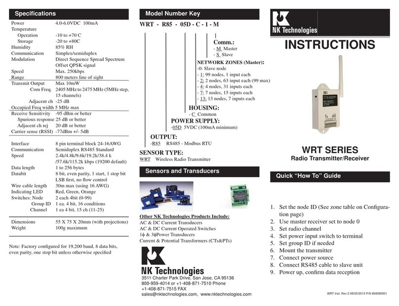
1. Set the node ID (0-99, same as slave device)
2. Use master receiver set to node 0
3. Set radio channel
4. Set power input switch to terminal
5. Set group ID if needed
6. Mount the transmitter
7. Connect power source
8. Connect RS485 cable to slave unit
9. Power up, confirm data reception
WRT SERIES
Radio Transmitter/Receiver
WRT - R85 - 05D - C
POWER SUPPLY:
-05D 5VDC
OUTPUT:
-R85 RS485 - Modbus RTU
SENSOR TYPE:
WRT Wireless Radio Transmitter
Model Number KeySpecifications
Power 4.0-6.0VDC 100mA
Temperature
Operation -10 to +70 C
Storage -20 to +80C
Humidity 85% RH
Communication Simplex/semiduplex
Modulation Direct Sequence Spread Spectrum
Offset QPSK signal
Speed Max. 250kbps
Range 800 meters line of sight
Transmit Output Max 10mW
Com Freq. 2405MHzto2475MHz(5MHzstep,
15 channels)
Adjacent ch -25 dB
Occupied Freq width 5 MHz max
Receive Sensitivity -95 dBm or better
Spurious response 25 dB or better
Adjacent ch rej 20 dB or better
Carrier sense (RSSI) -77dBm +/- 5dB
Interface 8 pin terminal block 24-16AWG
Communication Semiduplex RS485 Standard
Speed 2.4k/4.8k/9.6k/19.2k/38.4 k
/57.6k/115.2k kbps (9600 default)
Data length 1 to 256 bytes
Databit 8 bit, no parity, 1 start, 1 stop bit
LSB first, no flow control
Wire cable length 30m max (using 16 AWG)
Indicating LED Red, Green, Orange
Switches: Node 2 each 4bit (0-99)
Group ID 1 ea. 4 bit, 16 conditions
Channel 1 ea 4 bit, 15 ch (11-25)
Dimensions 55 X 75 X 20mm (with projections)
Weight 100g maximum
Quick “How To” Guide
Sensors and Transducers
Other NK Technologies Products Include:
AC & DC Current Transducers
AC & DC Current Operated Switches
1φ& 3φPower Transducers
Current & Potential Transformers (CTs&PTs)
HOUSING:
- C Common

The WRT is a Wireless data transmission device designed
to receive and transmit RS485 data packets. The product
is factory configured for Modbus RTU protocol. Each data
producing point (slave)can be connectedto oneWRTdevice,
and transmits the data to a second unit, which is connected
to the network master. Several slave data producers can be
connected together, to one WRT. Up to 99 slave units can
transmit to one master, and the units can be configured so
one network master can communicate with another network
through that network’s master.
Description
Installation
Configuration
1. No network communication
A. Check for node power. Confirm that the LEDs are
on: Green, Red, Orange. Check power source switch
position on the back of the node.
B. Cycle the power to clear from stand-by condition.
C. Check network wire connections, reverse + and-
D. Possible signal is blocked. Add another node or
E. Be sure that Node ID, channel selection and group ID
switch settings are correct. Each node must be unique
to the network and the same as user equipment ad-
dress. Master ID must be 0.
F. Check to be sure node and user equipment are set for
the same protocol (Modbus RTU).
Trouble Shooting
Power Wiring
Connect external source 4.0 to 6.0 VDC to terminal block,
or use 3.3 to 6.0 VDC produced by AC adaptor, remove
supplied plug and strip wires to terminate onto the radio
block.
Output Wiring
Connect control or monitoring wires to the sensor. Strip
the insulation back approximately 3/8 inch (10mm). If
solid wire, no tool is needed, just insert the wire into
terminal 7 (+) or terminal 8 (-) and the signal ground (6).
Terminals 3,4 and 5 are not used. Wire should be 24-16
AWG, 30 meters maximum. If using stranded wire, use a
small screwdriver to release the terminal securing block,
allowing for wire insertion.
Unit Switch
(RF-CH) Radio
Channel Frequency
0 11 ch 2405 MHz
1 12 ch 2410 MHz
2 13 ch 2415 MHz
3 14 ch 2420 MHz
4 15 ch 2425 MHz
5 16 ch 2430 MHz
6 17 ch 2435 MHz
7 18 ch 2440 MHz
8 19 ch 2445 MHz
9 20 ch 2450 MHz
A 21 ch 2455 MHz
B 22 ch 2460 MHz
C 23 ch 2465 MHz
D 24 ch 2470 MHz
E* 25 ch 2475 MHz
F* 25 ch 2475 MHz
* Note both positions E and F set channel 25
Each node in a networks will use the same channel
Node ID: Master is always
set to ID “0”, slave units set
to a value between 1 and 99.
One transceiver must be set
as the master and at least one
as a slave to the master.
Group ID: Select the same
group ID for all nodes on a
network. Contact factory for
other configurations.
Use 5VDC externalpower supply, and
bond the Modbus equipment ground
to the same ground as power supply.
If using an AC wall-type adaptor, re-
move supplied cord end and strip the
cord wires for termination on radio
block. Set this switch to “TERM”
position.
The WRT unit must be installed indoors or outdoors in
a suitable non-metallic enclosure. Each unit requires a 5
VDC power supply, and will need to be configured for
network address, channel frequency and group ID. The
radio can be screwed to a back panel or hung on a wall
with a nail or screw.
Back side of WRT
Set the node (radio) address
to the same value as the data
input device. If an address
higher than 99 is required,
contact the NK factory.

Network Connection Examples
One Master, Multiple Slave Nodes, One Input per Node One Master, Multiple Slave Nodes, Multiple Inputs per Node
One Master, Multiple Slave Nodes, Multiple Inputs per Node w/repeater
Troubleshooting (cont’d)
Precautions on Time-Out
There are 2 other Units or more in the same
network group with the signal strength of better
than -65dBm communicating with the Unit.
(*-65dBm is generally adequate strength of radio
signal)
There is 1 Unit in the same network group with
the signal strength of better than -65dBm nearby.
There is no Unit with better than -65dBm in the
network group, although weaker signals from
other Units are heard.
The Unit has not joined the network and no
signals are heard.
A message has been exchanged with another Unit
A messages has been exchanged with user
equipment
There is longer communication duration time with wireless vs. wired
networks. It is recommended that the baud rate between slave-node and
slave be as high as possible. A wired system “time-out” (duration of time
at master between 6th character of query and 1st character of response) is
10ms. Using a routing node between one slave node and a master node at
9600 baud increases this duration to 192ms. The time-out of the master
should be adjusted accordingly.
LED display of node
This manual suits for next models
1
Other NK TECHNOLOGIES Receiver manuals
