manuals.online logo
Brands
  1. Home
  2. •
  3. Brands
  4. •
  5. NK TECHNOLOGIES
  6. •
  7. Switch
  8. •
  9. NK TECHNOLOGIES AS1 - DODC - FL User manual

NK TECHNOLOGIES AS1 - DODC - FL User manual

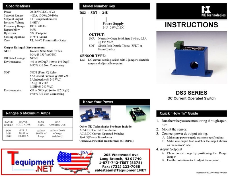
INSTRUCTIONS
1. Run the wire to be monitored through
aperture.
2. Mount the sensor.
3. Connect output wiring.
A. Use up to 14 AWG copper wires.
B. Ensure load matches the output shown on
the sensor label.
4. Adjust Setpoint
A. Use the potentiometer to adjust the set-
point.
AS1 DODC SERIES
AC Current Operated Switch
With Dual Output
AS1 - DODC - FL
CASE STYLE:
FL - Fixed Core, Top Terminals
OUTPUT (Solid State Switch):
DODC - Dual Normally Open, 1.0A @ 30VDC
SENSOR TYPE:
AS1 - AC current operated switch with single range
0.75A -- 20A
AS2 - AC current operated switch with single range
20A -- 50A
Model Number KeySpecifications
Power Required None - self powered
Output Switch Isolated Solid State Switch
Switch Rating DODC - N.O. 1A @ 30VDC
Off State Leakage <10 Microamps
Response Time 100 mS
Hysteresis < 8% of Setpoint
Set Point Ranges A Contact: Adjustable 0.75A - 20A
B Contact: Adjustable 0.75A - 20A
Start-up Delay 2.0 Seconds (fixed)
Setpoint Adjust 4 Turn potentiometer
Isolation Voltage Designed to meet UL508 require-
ments to 1,270 VAC
Tested to 5,000 VAC
Frequency Range 6-100Hz
Sensing Apeture -FL 0.75” (19mm)
Environmental -4 to122Deg F (-20 to 50 Deg C)
0-95% RH, Non Condensing
Ranges & Maximum Amps
Quick “How To” Guide
AS1-DODC-FL Inst. Rev 2 12/14 P/N 39-360-0001
3511 Charter Park Drive, San Jose, CA 95136
800-959-4014 or +1-408-871-7510 Phone
+1-408-871-7515 FAX
[email protected], www.nktechnologies.com
Know Your Power
Other NK Technologies Products Include:
AC & DC Current Transducers
AC & DC Current Operated Switches
1φ& 3φPower Transducers
Current & Potential Transformers (CTs&PTs)
TYPE RANGE MAXIMUM INPUTAMPS
FIXED CORE 0.75- 20 A
CONTINUOUS 6 SEC. 1 SEC.
50A 200A 400A
FIXED CORE 20-50 A 50A 200A 400A
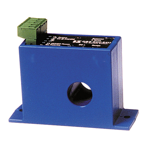
AS1 Series are self-powered, solid-state current-operated
switches which trigger when the current level sensed
through the apertureexceeds the adjusted setpoint. The solid
state output contacts can switch DC low voltage only; up
to 30 VDC, and up to one amp.
For All Versions
Run wire to be monitored through aperture (opening) in
the sensor.
AS1 switches can be located in the same environment as
motors, contactors, heaters, pull-boxes, and other electri-
cal enclosures. Mounting can be done in any position or
hung directly on wires with a wire tie. Ensure at least one
inch clearance exists between sensor and other magnetic
devices.
Description
Installation
Output Wiring
Setpoint Adjustment
Connect control or monitoring wires to the sensor. Use
up to 14 AWG copper wire and tighten terminals to 5
inch-pounds torque. Be sure the output load does not
exceed the switch rating.
CAUTION Incandescent lamps canhave “Cold Filament
Inrush” current of up to 10 times their rated amperage. Use
caution when switching lamps.
AS1SeriesSETPOINT isadjustedwith a4-turnpotentiom-
eter. The pot is shipped factory set to the lowest setpoint,
fully clockwise (CCW). Turning the pot counter-clockwise
(CW) will increase the setpoint. The pot has a slip-clutch to
prevent damage at either end of its rotation. To determine
where the adjustment is, turn the pot all the way CCW. This
will return it to the minimum setpoint.
Adjustment Notes:
1. Output contacts are solid-state. Check output status by
applying voltage to the contacts and reading the voltage
drop across the contacts. An Ohmmeter set on “Continu-
ity” will give misleading results.
2. It is recommended that setpoint be adjusted to allow for
voltage variations of 10-15%.
Typical Adjustment
1. Both “A” and “B” contacts are adjustable. Turn the pots
to minimum setpoint (4 turns CCW). Each contact has a
delay before closing of two seconds, but only during the
initial start up. This delay is not adjustable, but after the
1. Sensor is always tripped
A. The setpoint maybetoo low. Turn pot CWto increase
setpoint.
B. Switch has been overloaded and contacts are burned
out. Check the output load, remembering to include
inrush on inductive loads (coils, motors, ballasts)
2. Sensor will not trip
A. The setpoint may be too high. Turn pot CCW to
decrease setpoint.
sensor is in normal monitoring mode, the contact s will
close nearly instantaneously after current rise over the set
point.
2. Have normal operating current running through sensor.
Provided the monitored current is above 0.75A, both
outputs should be tripped since the trip points are at their
minimums. LEDs indicate the status of the contacts; slow
flashing (once every 2 to 3 seconds) indicates untripped
while fast flashing (2 to 3 times per second) indicates
contacts are tripped.
3. Turn the pot foreach contact setpoint adjustment CWuntil
the unit un-trips. This is indicated by the slow flashing of
the LED and by the changing of the output switch status.
The contacts are fully isolated from each other.
4. Now turn the pot CCW slowly until the unit trips again.
It now set at the current level being monitored.
A. To Set UNDERLOAD - Turn the pot about 1/8 turn
(or less) farther CCW.
B. To Set OVERLOAD - Turn the pot about 1/8 turn
(or less) farther CW.
B. Monitored current is below minimum required. Loop
the monitored wire several times through the aper-
ture until the “sensed” current rises above minimum.
Sensed Amps = (Actual Amps) x (Number of Loops).
Count loops on the inside of the aperture.
C. Switch has been overloaded and contacts are burned
out. Check the output load, remembering to include
inrush on inductive loads (coils, motors, ballasts).
Trouble Shooting
Setpoint
"A"
Setpoint
"B"
NORMALLY OPEN
"A" Contact
NORMALLY OPEN
"B" Contact
LED "A" LED "B"
AMPS
TIME
Startup
Inrush
Normal Operation Belt or
Coupling
Breaks
2 Sec. delay
Other NK TECHNOLOGIES Switch manuals

NK TECHNOLOGIES DS1-FD Series User manual

NK TECHNOLOGIES

NK TECHNOLOGIES DS1-FD Series User manual

NK TECHNOLOGIES DS3 Series User manual

NK TECHNOLOGIES

NK TECHNOLOGIES DS3 Series User manual

NK TECHNOLOGIES DS3 Series User manual

NK TECHNOLOGIES

NK TECHNOLOGIES DS3 Series User manual

NK TECHNOLOGIES DS1-FD Series User manual

NK TECHNOLOGIES

NK TECHNOLOGIES DS1-FD Series User manual

NK TECHNOLOGIES AS3 Series User manual

NK TECHNOLOGIES

NK TECHNOLOGIES AS3 Series User manual

Popular Switch manuals by other brands

Pacific Antenna Easy TR Switch manual

Pacific Antenna

Pacific Antenna Easy TR Switch manual

Roland V-800HD MKII Brochure & specs

Roland

Roland V-800HD MKII Brochure & specs

HP ProCurve 2510 Management and configuration guide

HP

HP ProCurve 2510 Management and configuration guide

Beijer Electronics JetNet 6228G Series installation guide

Beijer Electronics

Beijer Electronics JetNet 6228G Series installation guide

Crosscall X-SPACE manual

Crosscall

Crosscall X-SPACE manual

Gefen 2x2 HDMI Switcher user manual

Gefen

Gefen 2x2 HDMI Switcher user manual

IS5 COMMUNICATIONS iES6 Series user manual

IS5 COMMUNICATIONS

IS5 COMMUNICATIONS iES6 Series user manual

Korenix JetNet 2005f Quick installation guide

Korenix

Korenix JetNet 2005f Quick installation guide

Cisco 350XG series Administration guide

Cisco

Cisco 350XG series Administration guide

Rotech DRZ operating manual

Rotech

Rotech DRZ operating manual

Asante IntraSwitch 5324 Product release notes

Asante

Asante IntraSwitch 5324 Product release notes

Teledyne QMultiFlex-400 Installation and operating handbook

Teledyne

Teledyne QMultiFlex-400 Installation and operating handbook

SKF ST Installation, operation and maintenance manual

SKF

SKF ST Installation, operation and maintenance manual

Allied Telesis CentreCOM GS948MPX Command reference

Allied Telesis

Allied Telesis CentreCOM GS948MPX Command reference

TRENDnet TPE-1020WS Quick installation guide

TRENDnet

TRENDnet TPE-1020WS Quick installation guide

American DJ SC-8FC SYSTEM User instructions

American DJ

American DJ SC-8FC SYSTEM User instructions

SMC Networks SMC TigerAccess SMC7824M/ESW installation guide

SMC Networks

SMC Networks SMC TigerAccess SMC7824M/ESW installation guide

Crestron GreenLight DIN-8SW8 Installation & operation guide

Crestron

Crestron GreenLight DIN-8SW8 Installation & operation guide

manuals.online logo
manuals.online logoBrands
  • About & Mission
  • Contact us
  • Privacy Policy
  • Terms and Conditions

Copyright 2025 Manuals.Online. All Rights Reserved.