manuals.online logo
Brands
  1. Home
  2. •
  3. Brands
  4. •
  5. DANLERS
  6. •
  7. Switch
  8. •
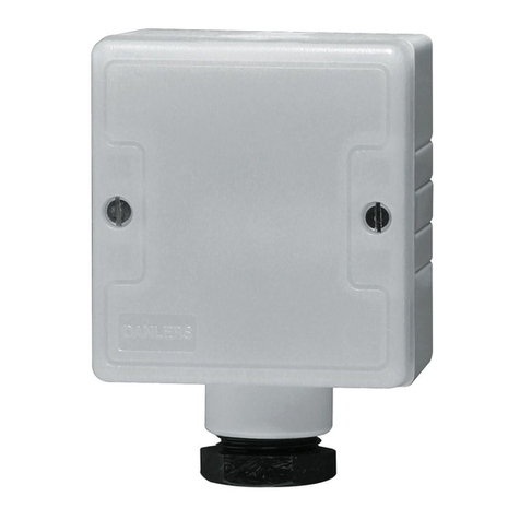
  9. DANLERS COPIR IP66 User manual

DANLERS COPIR IP66 User manual

DANLERS Limited, Vincients Road, CHIPPENHAM, Wiltshire, SN14 6NQ, UK.
Telephone: +44 (0)1249 443377 Fax: +44 (0)1249 443388 E-mail: [email protected]
www.danlers.co.uk
Company Registered Number 2570169 VAT Registration Number 543 5491 38
DAT0027 COPIR IP66 30/08/19 (Issue 001)
PLEASE READ THESE INSTRUCTIONS BEFORE INSTALLING THE PRODUCT
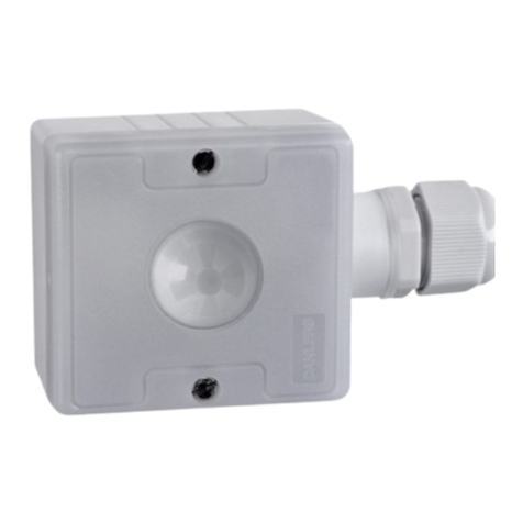
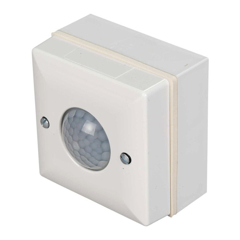
DANLERS COPIR IP66(BK) is IP66 rated and
can be surface mounted onto an external wall.
It incorporates a passive infra-red sensor to
detect movement of a warm body within the
detection zone (diagram 1) and it includes a
photocell to monitor the ambient light level.
The detection range is about 10 metres over
120 degrees, the range reduces to about 8m
at the extremes to prevent nuisance switching.
Product codes:
COPIR IP66: White enclosure (Grey front
facet).
COPIR IP66 BK: Black enclosure.
INSTALLATION PROCEDURE
1. Please read these notes carefully before
commencing work. In case of doubt please
consult a qualified electrician.
2. The detector should be sited so that it is not
shaded from daylight
3. The detector should be mounted between
1 and 2.2 metres high, via any of the four
pre-drilled mounting holes only.
4. It must be mounted with the cable entering
from below.
5. Make sure the power is isolated from the
circuit.
6. The detector should be connected as
shown in diagram overleaf.
L - Live in, N - Neutral in,
SL - Switched Line out.
7. IMPORTANT - Replace terminal cover.
8. Once the wiring has been completed and
verified, switch on the supply and test the
operation.
START UP MODE
When the PIR is powered up, the PIR will
switch on the lighting load for 1 minute then
switch it off. After 2 seconds it will switch
on again if it detects movement. With Time
set to minimum the load will stay on for 10
seconds so the detection range can be
easily assessed. If a manual override-off
switch after the PIR (diagrams 5 & 6, note 1)
it will not enter the start-up mode each time.
LOADING: See overleaf
LUX AND TIME SET UP
On detecting movement, if the ambient light is
dark enough, the COPIR IP66 (BK) will switch
the load on. The ambient threshold can be set
by the user to between approximately 10 and
1000 lux via the internal LUX adjuster (diagrams
2 and 3). The photocell can be disabled via the
internal mode button (see overleaf).
If no more movement is detected within a
pre-selected time, then the PIR switch will
turn the load off. This time lag can be set via
the TIME adjuster to 10 seconds, 20 seconds,
40 seconds, 80 seconds, 2 minutes 30
seconds, 5 minutes,10 minutes, 20 minutes
or 40 minutes (diagram 4).
For convenience, ensure that the TIME is set to
minimum when setting up the LUX level. Afterwards
set the TIME to a value suitable for the application.
1. When powered up, (after 1 minute
stabilisation time) turn lux pot (diagram
C) fully clockwise and time pot fully
anticlockwise.
2. Press the MODE button (diagram 2) for
approximately 0.5s. The LED will go green
indicating the LUX cell is active. (Or press
and hold button for approx. 4 seconds – LED
goes RED indicating Lux cell INACTIVE).
Repeating these steps will toggle the
functionality.
3. If lux cell active, vacate area until PIR switch
switches the load off (should be after 10
seconds).
4. With the LUX as desired on working plane
from daylight ONLY (no artificial light), wind
the lux pot anticlockwise whilst waving your
hand in front of the PIR cell. When the PIR
switches the load ON, stop turning the pot.
The Lux inhibit level is now set.
5. Turn the PIR time to the desired timeout
(diagram 4).
Whenever a person is detected,
the time lag will start again and the load will
stay switched on.
TROUBLESHOOTING
The PIR does not detect:
• Check power supply.
• Is there an obstruction in front of the lens?
• Person is too far from the COPIR IP66
switch, see detection diagram.
• Person is moving unusually slowly (perhaps
when testing).
• To perform detection test - turn the time
spindle to minimum setting (10 seconds),
cover the lens to stop any detection - load
should switch off in 10 seconds unless going
through its START UP MODE (see opposite).
The PIR stops working
• Ensure the unit is mounted correctly so that
no water can enter.
The PIR false triggers
• Detector is exposed to air movement on
breezy days.
COPIR IP66, COPIR IP66BK
Compact Person Detection Switches
Input: 220-240 Vac 50Hz
Dual colour LED:
RED - PIR active,
Photocell inactive
GREEN - PIR and
Photocell override ON
(passive LUX)
Lux Cell
Mode
Time
Delay
Spindle
Lux
Setting
Spindle
MODE
STATUS
TIME LUX
10
1000
DIAGRAM 2 - TIME / LUX ADJUSTERS (INSIDE CASING)
TIME
min max
LUX
max min
10 LUX
40m
20m
10m
5m
2.5m
80s
10s
20s
40s
1000 LUX
Use Mode
Button to
disable LUX
(see diagram
2)
DIAGRAM 3 - LUX ADJUSTMENT
DIAGRAM 4 - ADJUSTING TIME LAG
TIME
min max
LUX
max min
10 LUX
40m
20m
10m
5m
2.5m
80s
10s
20s
40s
1000 LUX
Inside
detector
housing
Locate safety cap plastic
pins in the hole ‘L’ and
second ‘N’ holes above
the termination screws.
Press firmly to attach.
Terminal cover
(safety cap)
DIAGRAM 1 - WALL MOUNTED DETECTION
Strong detection zone (5m)
i.e. person walking
towards detector
Secondary
detection zone
(10m, 8m at
extremes)
i.e. person walking
perpendicular to
detector
Recommended mounting
height 1 to 2.2 metres
DIAGRAM 5 - TERMINAL COVER
DANLERS Limited, Vincients Road, CHIPPENHAM, Wiltshire, SN14 6NQ, UK.
Telephone: +44 (0)1249 443377 Fax: +44 (0)1249 443388 E-mail: [email protected]
www.danlers.co.uk
Company Registered Number 2570169 VAT Registration Number 543 5491 38
DAT0027 COPIR IP66 30/08/19 (Issue 001)
PRECAUTIONS AND WARRANTY
This product conforms to BS EN 60669-2-1 and
BS EN 55015.
Please ensure the most recent edition of the
appropriate local wiring regulations are observed
and suitable protection is provided e.g. a 10 amp
circuit breaker and voltage surge protection.
Please ensure that this device is disconnected
from the supply if an insulation test is made.
Other DANLERS Product ranges
-Remotely adjusted PIR occupancy switches
-Manually adjusted PIR occupancy switches
-Microwave switches
-Daylight linked dimming controls
-Photocell switches
-Time lag switches
-Outdoor security switches
-Dimmer switches inc. LED dimming
-HVAC controls
-Radio remote (RF) controls
Please call for more information or visit our website.
This product is covered by a warranty which
extends to 5 years from the date of manufacture.
MADE IN THE UK
INPUT:
Voltage: 220 - 240Vac
Frequency: 50Hz
LOADING:
Resistive loads: 10 amps (2300W)
Fluorescent: 10 amps (2300W)
LED Drivers and
LED lamps and
fittings:
6 amps (1500W)
(PF ≥0.95)
Electronic and
wire wound
transformer:
3 amps (750W)
CFL and 2D
lamps: 2 amps (500W)
Fans: 1 amp (250W)
Minimum load
2W resistive, suitable
for most energy saving
lamps, LEDs and
emergency fittings.
OPERATING CONDITIONS:
The temperature difference between the
detection target and the background must
be at least 4 °C.
Ambient
temperature: -20... +40 °C
Storage
temperature: -25... +75 °C
Max. relative
humidity:
0... 80%,
non-condensing
CONNECTORS:
Terminal block
Wire size:
0.5mm2- 2.5mm2solid
or stranded
Wire strip
length: 6-7mm
Tightening
torque: 0,4 Nm/4 Kgf.cm
COPIR IP66, COPIR IP66BK
Compact Person Detection Switches
Input: 220-240 Vac 50Hz
MECHANICAL DATA:
Dimensions: 75mm x 60mm x 37mm
Weight: 100g (unpacked)
Degree of
protection: IP66
Protection class: Built-in Class 2
Material (casing)
Flame-retardant
polycarbonate/
Polypropylene.
Finish / Colour
COPIR IP66:
Matt /White (RAL 9003)
COPIR IP66 BK:
Black (RAL 9005)
CONFORMITY AND STANDARDS:
EMC emission: EN60669-2-1:2004 inc.
A12:2010
EMC immunity: EN60669-2-1:2004 inc.
A12:2010
Safety: EN60669-2-1:2004 inc.
A12:2010
Environment: Complies with WEEE
and RoHS directives
TECHNICAL DETAILS
WIRING DIAGRAMS
L
load
Note 1: Optional
manual wall switch
for overriding off.
N
230 VAC
SL NLCOPIR IP66 (BK)
7. WIRING A SINGLE PIR
PLEASE READ THESE INSTRUCTIONS BEFORE INSTALLING THE PRODUCT
DIMENSIONS
6. DIMENSIONS IN MM
10
65
37
24
60
frontside
20mm threaded
entry spout
inside
4 x mounting
holes. 3M screws
recommended
(not supplied)
17
48

This manual suits for next models

1

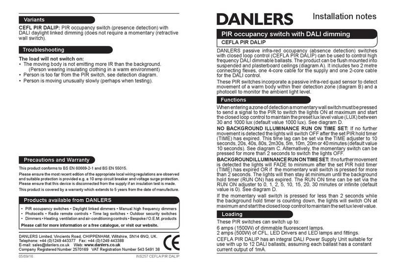
Other DANLERS Switch manuals

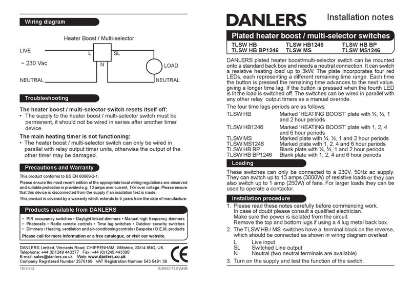
DANLERS TLSW HB Quick start guide

DANLERS

DANLERS TLSW HB Quick start guide

DANLERS EasyZAPP EZ CEFL Quick start guide

DANLERS

DANLERS EasyZAPP EZ CEFL Quick start guide

DANLERS CEFLAPIR Quick start guide

DANLERS

DANLERS CEFLAPIR Quick start guide

DANLERS CESRA PIR DSIP Quick start guide

DANLERS

DANLERS CESRA PIR DSIP Quick start guide

DANLERS WACE RFS Quick start guide

DANLERS

DANLERS WACE RFS Quick start guide

DANLERS CESRAPIRSD Quick start guide

DANLERS

DANLERS CESRAPIRSD Quick start guide

DANLERS TLSW HB Quick start guide

DANLERS

DANLERS TLSW HB Quick start guide

DANLERS CESF PIR User manual

DANLERS

DANLERS CESF PIR User manual

DANLERS ControlZAPP CZ CEFL Quick start guide

DANLERS

DANLERS ControlZAPP CZ CEFL Quick start guide

DANLERS CEFL PIR Quick start guide

DANLERS

DANLERS CEFL PIR Quick start guide

DANLERS TLSW 10 ILM Quick start guide

DANLERS

DANLERS TLSW 10 ILM Quick start guide

DANLERS GRTL MK Quick start guide

DANLERS

DANLERS GRTL MK Quick start guide

DANLERS BMEXPIR Quick start guide

DANLERS

DANLERS BMEXPIR Quick start guide

DANLERS ControlZAPP CZ CEFL DALI Quick start guide

DANLERS

DANLERS ControlZAPP CZ CEFL DALI Quick start guide

DANLERS ControlZAPP CZ CESR 10VDC Quick start guide

DANLERS

DANLERS ControlZAPP CZ CESR 10VDC Quick start guide

DANLERS CESF PIR User manual

DANLERS

DANLERS CESF PIR User manual

DANLERS GRTLA MK Quick start guide

DANLERS

DANLERS GRTLA MK Quick start guide

DANLERS CEPH NO Quick start guide

DANLERS

DANLERS CEPH NO Quick start guide

DANLERS CESF PIR Quick start guide

DANLERS

DANLERS CESF PIR Quick start guide

DANLERS CESRA PIR 10VDC Quick start guide

DANLERS

DANLERS CESRA PIR 10VDC Quick start guide

DANLERS WAPIR Quick start guide

DANLERS

DANLERS WAPIR Quick start guide

DANLERS BMPIR10M Quick start guide

DANLERS

DANLERS BMPIR10M Quick start guide

DANLERS CZ HB ND Quick start guide

DANLERS

DANLERS CZ HB ND Quick start guide

DANLERS CESFPIRSV Quick start guide

DANLERS

DANLERS CESFPIRSV Quick start guide

Popular Switch manuals by other brands

NETGEAR JFS516 Brochure & specs

NETGEAR

NETGEAR JFS516 Brochure & specs

Raritan MCIP116 Quick installation and setup guide

Raritan

Raritan MCIP116 Quick installation and setup guide

Belimo NFB Series Mounting Installation Instructions

Belimo

Belimo NFB Series Mounting Installation Instructions

Madas CE-51AT1438 manual

Madas

Madas CE-51AT1438 manual

HP 3600 v2 Series Configuration guide

HP

HP 3600 v2 Series Configuration guide

NETGEAR GS724TPv2 Installation

NETGEAR

NETGEAR GS724TPv2 Installation

EKL KHU-0401 quick start guide

EKL

EKL KHU-0401 quick start guide

ATEN UH-125 user manual

ATEN

ATEN UH-125 user manual

SignaMax 065-7508 user manual

SignaMax

SignaMax 065-7508 user manual

NETGEAR FS605 v3 installation guide

NETGEAR

NETGEAR FS605 v3 installation guide

iNels RFSAI-11B-SL manual

iNels

iNels RFSAI-11B-SL manual

Digitus DC-11201-1 user manual

Digitus

Digitus DC-11201-1 user manual

ATEN VanCryst VM3200 user manual

ATEN

ATEN VanCryst VM3200 user manual

Leviton 47693-ESM Product specifications

Leviton

Leviton 47693-ESM Product specifications

Emcotec RC Electronic SPS-RCS quick start guide

Emcotec

Emcotec RC Electronic SPS-RCS quick start guide

Panasonic Switch-S24GPWR installation guide

Panasonic

Panasonic Switch-S24GPWR installation guide

Barksdale D1T operating instructions

Barksdale

Barksdale D1T operating instructions

ATEN Master View ACS-1208A user manual

ATEN

ATEN Master View ACS-1208A user manual

manuals.online logo
manuals.online logoBrands
  • About & Mission
  • Contact us
  • Privacy Policy
  • Terms and Conditions

Copyright 2025 Manuals.Online. All Rights Reserved.