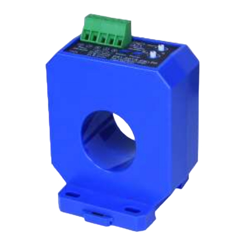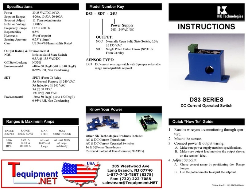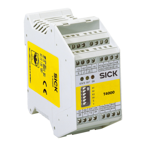
DS3 Series are DC current operated switches. They operate
(switch) when the current level through the hole exceeds the
adjustable setpoint. They accept 24VAC or 24VDC power.
The outputs areisolated from the input andthe power supply.
The sensor can be supplied with solid-state output (-NOU)
or with form C relay output (-SDT ).
Run wire to be monitored through opening in the sensor.
DS3switches work in the sameenvironmentas motors, con-
tactors, heaters, pull-boxes, and other electrical enclosures.
They can be mounted in any position or hung directly on
wires with a wire tie. Just leave at least one inch distance
between sensor and other magnetic devices.
Description
Installation
Setpoint Adjustment
Range & Setpoint
DS3 switches have two setpoint adjustment mechanisms:
1. Select the setpoint RANGE with the Range Jumper.
2. Fine tune the SETPOINT with the 11 turn potentiom-
eter (pot).
The 11 turn pot is shipped from the factory set fully counter
clockwise (CCW) to the lowest setpoint. Turning the pot
clockwise (CW) will increase the setpoint. The pot has a
slip-clutch to prevent damage at either end of its rotation.
To determine where theadjustment is, turn the pot atleast 11
times CCW. This will return it to the minimum setpoint.
Adjustment Notes:
1. NOU output contacts aresolid-state. Check output status
by applying a small load and reading the voltage drop
across the contacts. Anohmmeterwillgivemisleading
results.SDT output contacts are mechanical, and can be
tested with an ohmmeter.
2. We recommend adjusting setpoint to allow for normal
voltage variations.
3. Adaptive Hysteresis (deadband) is 5% of the setpoint.
This allows sensitivity at low setpoints while eliminating
dithering and output chattering at high setpoints.
Output LED
MONITORED
AMPS
OPEN
OPEN
CLOSED
CLOSED
CLOSED
OPEN
OUTPUT TYPE
N.O. N.C.
OFF
OFF
ON
None or below range
Below trip level
Above trip level
1. Sensor is always tripped
A. The jumper may be set in a range that is too low for
current being monitored. Move jumper to the correct
range.
B. The setpoint maybetoolow. Turn pot CWto increase
setpoint.
C. Switch has been overloaded and contacts are burned
out. Check the output load, remembering to include
inrush on inductive loads (coils, motors, ballasts)
Typical Adjustment
1. Make sure all wiring is correct, all terminals are tight and
that power is on (green power LED)
2. Move the jumper to the desired range. Turn the pot to
minimum setpoint (11 turns CCW).
3. Have normal operating current running through sen-
sor. The output should be tripped and red output LED
“ON”.
3. Turn the pot CW until the unit un-trips. This is indicated
by the LED going off and by the output switching.
4. Now turn the pot CCW slowly until the unit trips again.
It now set at the current level being monitored.
A. To Set UNDERLOAD - Turn the pot about 1/8 turn
further CCW.
B. To Set OVERLOAD - Turn the pot about 1/8 turn
further CW.
2. Sensor will not trip
A. Unit is not powered. Check power supply and power
wiring.
B. The jumper may be set in a range that is too high for
current being monitored. Move jumper to the correct
range.
B. The setpoint may be too high. Turn pot CCW to
decrease setpoint.
C. Switch has been overloaded and contacts are burned
out. Check the output load, remembering to include
inrush on inductive loads (coils, motors, ballasts).
Trouble Shooting
Power Wiring
Connect 24 VAC or 24 VDC (or 12 Volts depending on the
model) power to Terminals 1 and 2. Tighten to 4.5 In-Lb
torque. The connection is not polarity sensitive. Terminals
are removable to make wiring easier. Be sure to seat the
terminal properly in the location marked “Power”
Output Wiring
Connect control or monitoring wires to the sensor. Use
up to 12-22 AWG copper wire and tighten terminals to 4.5
In-Lb torque. Be sure the output load does not exceed the
switch rating.
Incandescent lamps can have “Cold Filament Inrush” cur-
rent of up to 10 times their rated amperage. Use caution
when switching lamps, especially with solid state output
sensors.
3 4
1 2
Power 3 4 5
G R
R
Partial View “-NOU”
Models
Isolated Solid State Output
(Shown De-Energized)
Power Supply
12 or 24VAC/DC
Isolated Relay Output
(Shown De-Energized)
Setpoint
- +
Top View “-SDT”
Models
