NLS X-32 User manual

Non-Linear Systems
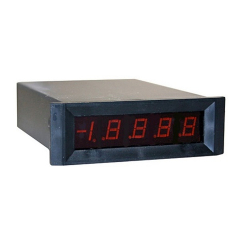
X-32 3-Digit
Short Depth
Digital Panel Meter
INSTRUCTIONS
OVERVIEW
The X-32 Digital Panel Meter is a unipolar,
three-digit, fixed-range, DC voltmeter. It
features auto zeroing, eliminating zero drift.
The X-32 is a short depth meter of which
requires only one-half inch to mount behind
panel. Calibration at full-scale can be
accomplished by adjusting a single
potentiometer accessible from the front of
the meter.
A mating connector option provides plug-in
connections of the external leads. This
connector, if required, must be ordered
separately. (Part number 53-106).
The X-32 is built to a standard 1 volt range,
yet is also available in five other ranges.
(Select 100 mV, 10 V, 100 V or 1000 V
range) The factory can make this range
modification, or, you can accomplish this
range change by purchasing the range
change kit. (Part number 53-107)
A current measurement option is available,
permitting measurement of DC current from
100 nano amperes full scale (F.S.) to 1
amperes full scale (F.S.). (Part number
53-108)
An external +5Vdc regulated power supply
is recommended for operation. A typical
configuration for a suitable power supply is:
Figure 1: Power Supply Schematic
SPECIFICATIONS
Accuracy: + 0.2% Full Scale
Normal-Mode Rejection:
40 dB minimum.
Common-Mode Rejection:
80 dB minimum.
Common-Mode Voltage:
-1.5V to +4V between signal LO and
negative terminal of power supply.
Display: 0.56" bright Red LED, also
available in yellow, green, or orange
LEDs.
Decimal Location: Positioned by
internal jumper to any one of three
locations: X,X,X, (1V F.S. range
reads mV XXX)
Input Voltage Protection:
+ 250 Vdc on four lowest ranges.
+1200 Vdc on 1000 V range.
Input Z: 100 M
, 100 mV Full Scale,1
M
,1V, 10V, and 100V Full Scale,
4M
, 1000V Full Scale
Measurement Method: Integration;
input integration time - 80 mSec.
Operating Temperature:
0°C to +50°C ambient
Overload or Negative Indication:
Display is blank for inputs exceeding full
scale or for negative polarity input.
Power: +5 Vdc +5% @ 175 mA
Ranges: 0 to 100mV
0 to 1V
0 to 10V
0 to 100V
0 to 1000V
Ratio Operation: Ratio
measurements may be made by
using an external reference.
Settling Time: 1 sec. F.S. input chg.
Update Rate: 3readings/sec nominal
Temp Coefficient: 100ppm/C typical
Warm-up Time: 10 seconds
to + 0.1% accuracy.
Weight: 2 oz (56.7 grams) approx.
Zero Stability: Auto-zeroing
eliminates zero drift.
INSTALLATION
1. Mount the X-32 as follows:
a. Cut hole in panel 3.622" (92mm)
W x 1.693": (43mm) H.
b. Insert meter from the front,
through panel cutout.
c. Fit mounting clips (2) into slots
located on top and bottom of
meter. The foot of the clip should
face forward.
d. Thread screws (2) into clips &
tighten screws against rear
surface of panel.
2. If you have purchased the mating
connector option (NLS P/N 53-106),
install a keying tab in the connector
(Position 2) and attach the hookup
wire to the individual connector
sockets. Insert the sockets into the
connector block making sure the
keying tab and sockets are in the
proper position to latch into the
rectangular holes on the block.
(Refer to Table 1). Positions 3, 4, 5
and 8 do not have sockets.
Figure 2:Outline drawing of X-32 case

Table 1. Connector Pin Information
1. Signal HI 6. Signal LO
2. Key 7. Ground
3. N/C 8. N/C
4. N/C 9. +5Vdc
5. N/C 10. Ext. Ref.
Operation
1. Connector. The connector (purchased
separately) after assembling, is plugged onto
pins at rear of meter. Line up connector key
with missing pin in position 2. Pin 1 in Figure
3 is the pin that's by itself. Pin 2, 3, 4 and 5
are not installed on the PC board of the
meter.
2. Power Supply. Connect the negative
side of the +5 Vdc power supply to pin 7 of
the connector and the positive side to pin 9.
3. Signal. For most applications it is
desirable to have SIGNAL LO (Pin 6)
connected to power ground (pin 7).
As shipped, the meter makes this
connection with a printed circuit trace
labeled "W1." Connect signal HI and signal
LO of the source to pins 1 (HI) and 6 (LO)
respectively of the meter. A shielded cable
may be required if the signal source has a
high resistance. If there is any connection
between source LO and power ground
(other than W1), and if instability is observed
in the least significant digits of the display,
this instability may be improved by cutting
the W1 PC trace.
4. Decimal Location. Depending upon
which decimal point is to be illuminated,
install a jumper wire between circuit board
C and circuit board L, M or R on the inside
of the meter, See below:
Decimal Location X .X . X .
Pad Location L M R
5. Readings. With +5 Vdc power and
positive signal voltage applied (within range
of meter) , the X-32 will display the correct
reading + 0.1% within 10 seconds.
Ratio Operation
For ratio measurement applications, an
external reference voltage may be used as
follows: (In the ratio mode, the calibration
potentiometer, R2, has no effect.)
Remove jumper W2 by cutting
PC trace.
Install jumper W3. (See Figure 3)
Connect an external reference
voltage of +0.1 volt +10% to pin 10.
Voltage Range Modification
The X-32 may be range-changed from
any range to another by the installation
of various precision resistors.
1. Remove faceplate in front of display by
pressing in on sides of bezel and pulling
faceplate out by bowed center. Remove two
screws located at either end of display.
2. Carefully remove meter from front
of case.
3. Observe resistor values that are in meter
and compare to figure 3 and table II. Install
resistors specified in table II to attain desired
range.
Table II.
Resistor Values in
Range Modification Kit
Range 100mV 1V 10V 100V 1000V
R8 - 100k 10k 1k 402
R9 Jumper 909k 1M 1M -
R10 - - - - 1M
R11 - - - - 1M
R12 - - - - 1M
R13 - - - - 1M
4. If a decimal point is desired, see #4 under
Operation.
5. Clean solder joints & adjacent areas on
printed circuit board to minimize leakage
paths.
6. Reassemble meter.
7. Calibrate meter , see Calibration section.
8. Range change modification are available,
(NLS P/N 53-107).
Calibration
1. Set power supply voltage +5Vdc +2%.
2. Allow 5 minutes for warm up.
3. Precision DC power supply voltages:
Range of Recommended
Instrument Calibration Voltage
100 mV 90 mVDC
1 V 900 mVDC
10 V 9.00 VDC
100 V 90.0 VDC
1000 V 900 VDC
4. Adjust potentiometer R2 at side of
meter until readout agrees with input.
Figure 3. Component Location
Current Operation
Current Range Kit NLS P/N 53-108
provides all the resistors required to
measure DC currents. The meter must be in
the 100 mV range to accomplish this. Refer
to Figure 3 & 4 and Table III, for position of
R14. Higher currents are measured by
using an external current shunt. See
Table III for resistor values.
(Call factory for requirements)
Warning: This meter is frequently
used on the high side of the current
source to be measured. This
arrangement may cause a short
between the circuit high side and
ground with possible damage to the
meter and circuit. To prevent this, an
isolated meter power supply is
recommended.
Table III. Shunt Resistor Values
Full Scale Shunt Resistor
Current Range Value
100 Nanoamperes 1 Megohm
1 Microampere 100 Kilohms
10 Microamperes 10 Kilohms
100 Microamperes 1 Kilohm
1 Milliampere 100 Ohms
10 Milliamperes 10 Ohms
100 Milliamperes 1 Ohm
1 Ampere 0.1 Ohm
Figure 4. Current Shunt Location
Specifications Subject to Change
without Notice
Non-Linear Systems
Originator of the digital voltmeter.
San Diego, CA
P: 619-521-2161
F: 619-521-2169
sales@nonlinearsystems.com
11-14
Other NLS Measuring Instrument manuals
