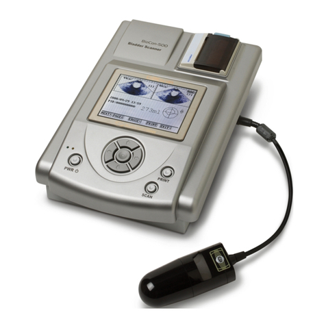
Mcube BioCon-500 User manual

Service Manual

Service Manual for BioCon-500TM
Mcube Technology Co., Ltd. i
www.mcubetech.co.kr
CUBEscan BioCon-500 Service Manual
The Information contained in this service manual is proprietary to the Mcube Technology
Co., Ltd. It is only used for convenience of our customers. It may not be changed in whole
or in part without the written notice.
Any service work performed by persons who are not authorized by Mcube Technology Co.,
Ltd. may void your warranty.
This service manual contains technical contents for service as below.
-Product configuration
Product configuration and block diagram
Product components and their functions
Signal interface and their definition
-Structure and assembling of the device
Structure and components
Assembling sequence
-Signal test
-Troubleshooting

Service Manual for BioCon-500TM
Mcube Technology Co., Ltd. ii
www.mcubetech.co.kr
Table of Contents
Contents
Pa
ge
1. Product Configuration --------- 1
1.1 Maintenance Mode Password --------- 1
1.2 Product Configuration --------- 2
1.3Signal Interface --------- 4
1.3.1 Signal Interface of the Control Board --------- 5
1.3.2 Signal Interface of the Analog Board --------- 11
1.3.3 Signal Interface of the Key Board --------- 13
1.3.4 Signal Interface of the ChargeBoard --------- 14
1.3.5 Signal Interface of the Battery Board --------- 15
2. The Components of the Product --------- 16
2.1 DC Adapter --------- 16
2.2 Ultrasonic Probe --------- 17
2.3 Battery Module --------- 17
2.4 LCD Module --------- 18
2.5 Printer Module --------- 19
2.6 Charge Board --------- 19
2.7 Analog Board --------- 20
2.8 Control Board --------- 22
3. Structure and Assembling of the Device --------- 24
3.1. Structure and Assembling of the Upper Case --------- 24
3.1.1. Structure and Components of the Upper Case --------- 24
3.1.2. Assembling of the Upper Case --------- 26
3.2. Structure and Assembling of the Lower Case --------- 27
3.2.1. Structure and Components of the Lower Case --------- 27

Service Manual for BioCon-500TM
Mcube Technology Co., Ltd. iii
www.mcubetech.co.kr
3.2.2. Assembling of the Lower Case --------- 29
3.3. Structure and Assembling of the Console --------- 30
3.3.1. Structure and Components of the Console --------- 30
3.3.2. Assembling of the Console --------- 31
3.4. Structure and Assembling of the Ultrasonic Probe
Module
---------
32
3.4.1. Structure and Components of the Ultrasonic
Probe Module
---------
32
3.4.2. Assembling of the Ultrasonic Probe Module --------- 33
4. External Cable Configuration --------- 34
4.1. DC Adapter Cable --------- 34
4.2. Ultrasonic Probe Cable --------- 35
4.3. USB Cable --------- 36
5. Signal Test --------- 37
5.1. Test for Analog board --------- 37
5.1.1. Power Test --------- 37
5.1.2. TCG1 Test --------- 38
5.1.3. TCG2 Test --------- 39
5.1.4. Ultrasonic Pulse Test --------- 40
5.2.Test for the Control Board --------- 41
5.2.1. Power Test --------- 41
5.2.2. LCD Test --------- 41
6. Troubleshooting --------- 46
7. Maintenance Mode --------- 50
8. Calibration Procedures --------- 54
8.1 Purpose --------- 54
8.2 Scope --------- 54
8.3 Supported Firmware Version --------- 54

Service Manual for BioCon-500TM
Mcube Technology Co., Ltd. iv
www.mcubetech.co.kr
8.4 General --------- 54
8.5 Procedures --------- 55
8.5.1 Calkit calibration --------- 55
8.5.2 CubeScan Phantom Calibration --------- 59
8.5.3 Dansk Phantom Calibration --------- 61
8.6 Error Messages during CaliKit Calibration and
CubeScan Phantom Calibration
--------- 65

Service Manual for BioCon-500TM
Mcube Technology Co., Ltd. 1
www.mcubetech.co.kr
1. Product Configuration
1.1 Maintenance Mode Password
BioCon-500 has two system modes. One is Normal mode, and the other is
Maintenance mode. Normal mode is for the normal user, and Maintenance mode is for
the technicians in the hospital or service engineers. To enter the maintenance mode,
push LEFT key with ENTER key being pushed and then push PRINT key after the
system is turned on and the top screen is displayed in normal mode. When you press
‘ENTER+LEFT+PRINT’keys, the BioCon-500 asks for the Maintenance mode
password (after the firmware version 3.1.009). Input ‘1122’for the password. You
cannot change the password.

Service Manual for BioCon-500TM
Mcube Technology Co., Ltd. 2
www.mcubetech.co.kr
1.2 Product Configuration
BioCon-500TM is a 3-dimensional ultrasonic equipment to measure the bladder volume
and quantity of remaining urine safely and comfortably through non-invasive method. Its
overall structure is as below.
(System Configuration of BioCon-500)

Service Manual for BioCon-500TM
Mcube Technology Co., Ltd. 3
www.mcubetech.co.kr
The system, in large, consists of a console, an ultrasonic probe, and a DC adapter
Component Function
DC Adapter Supplies a DC power required in the Charge Board for charging
at the system.
Console Controls system operation and various signals, and handles
signal transmission and reception.
Ultrasonic Probe Transmits and receives the ultra
sonic signals, being used in close
contact with the patient.
The Console consists of a printer module, aLCD module, a battery module, and a
number of boards. Its functions are as below.
Component Function
ChargeBoard Charges the battery module with DC 16V input from a DC
adapter.
Battery Board Connects the ChargeBoard and the Battery Module.
Analog Board
Transmits an ultrasonic pulse to the ultrasonic probe, processes
the signal just received,and transmits the data transferred
through the A/D converter to the control board. It also drives the
stepping motorsrequired in imaging.
Connection Board Input from a user.
Key Board Performs interfacing between the users and the system.
Control Board
Controls the overall system with following major functions.
-Processes user’s input.
-Drives the stepping motor of the thermal printer and
transmits data
-Controls the charging of a battery module
-Interfaces PC through USB.
-Displays data on LCD
-Processes data received from the Analog Board
Battery Module Provides the power required in the system.
LCD Module Displays various information.
Printer Module Prints the information about the bladder and bladder images on
the thermal paper

Service Manual for BioCon-500TM
Mcube Technology Co., Ltd. 4
www.mcubetech.co.kr
1.3Signal Interface
The signal interface for the system is as below.
(Structure of Signal Interface at BioCon-500)
Control
Board
J4
Connection
Board
JP3
JP2
JP1
JP5
JP4
JP6
JP3
JP2
JP1
Analog Board
JP5
JP4
JP101
JP2
JP1
JP3
Charging
Board J7
J5
J4
J2
J6
Key Board
Battery
Module
J2
J1
Ultrasonic
Probe
PC
USB
JP7
Battery
Board
J3J1
J1
JP6
JP7
Printer
Module
JP5 JP4
JP1
JP2
J2
LCD Module
DC Adapter

Service Manual for BioCon-500TM
Mcube Technology Co., Ltd. 5
www.mcubetech.co.kr
1.3.1 Signal Interface of the Control Board
JP1 is a connector to exchange the data with ADC (Analog-Digital Converter) in the
Analog Board. And each signal is defined as below.
JP1
TO: Analog Board Connection
Pin No.
Name I/O Description
1FH_DB0 In AD Conversion Data In bit 0
2FH_DB1 In AD Conversion Data In bit 1
3FH_DB2 In AD Conversion Data In bit 2
4FH_DB3 In AD Conversion Data In bit 3
5FH_DB4 In AD Conversion Data In bit 4
6FH_DB5 In AD Conversion Data In bit 5
7FH_DB6 In AD Conversion Data In bit 6
8FH_DB7 In AD Conversion Data In bit 7
9FH_DB8 In AD Conversion Data In bit 8
10 FH_DB9 In AD Conversion Data In bit 9
11 FH_DB10 In AD Conversion Data In bit 10
12 FH_DB11 In AD Conversion Data In bit 11
13 FH_BLANK Out Blank signal
14 FH_AD_CS Out ADC chip select
15 FH_AD_RD Out ADC Read
16 FH_CONVST Out ADC Conversion Start
17 FH_AD_CLK Out ADC clock
18 FH_AD_BUSY In ADC busy
19 FH_POS_PULSE Out To generate positive pulse
20 PH_NEG_PULSE Out To generate negative pulse

Service Manual for BioCon-500TM
Mcube Technology Co., Ltd. 6
www.mcubetech.co.kr
JP2 is a connector representing a power from the analog board and other various
signals. And each signal is defined as belows.
JP2
To: Analog Board Connection
Pin
No. Name I/O Description
1H_BAT_UNSWITCHED Power Input power from analog board
2H_BAT_UNSWITCHED Power Input power from analog board
3H_BAT_UNSWITCHED Power Input power from analog board
4H_BAT_UNSWITCHED Power Input power from analog board
5SWITCHING_ON Out To say that control board is on.
6--Reserved
7--Reserved
8--Reserved
9--Reserved
10 --Reserved
11 --Reserved
12 --Reserved
13 VDD Power ADC digital logic power
14 VDD Power ADC digital logic power
15 Ground Power Ground signal
16 Ground Power Ground signal
17 Ground Power Ground signal
18 CH_AN_PWR_ON Out Analog board power on/off
19 CH_SCLK in Probe detection signal
20 FH_SCAN_SW In Probe scan switch input

Service Manual for BioCon-500TM
Mcube Technology Co., Ltd. 7
www.mcubetech.co.kr
JP3 is a connector to exchange the data with the stepping motor built in the
ultrasonic probe. And each signal is defined as below.
JP3
To: Analog Board Connection
Pin
No. Name I/O Description
1FH_MOT_CON1 Out Probe motor driver control signal
2FH_MOT_CON2 Out Probe motor driver control signal
3FH_MOT_CON3 Out Probe motor driver control signal
4FH_MOT_CON4 Out Probe motor driver control signal
5FH_MOT_CON5 Out Probe motor driver control signal
6FH_MOT_CON6 Out Probe motor driver control signal
7FH_MOT_CON7 Out Probe motor driver control signal
8FH_MOT_CON8 Out Probe motor driver control signal
9FH_MOT_CON9 Out Probe motor driver control signal
10 FH_MOT_CON10 Out Probe motor driver control signal
11 FH_MOT_CON11 Out Probe motor driver control signal
12 FH_MOT_CON12 Out Probe motor driver control signal
13 FH_MOT_CON13 Out Probe motor driver control signal
14 FH_MOT_CON14 Out Probe motor driver control signal
15 FH_MOT_CON15 Out Probe motor driver control signal
16 FH_MOT_CON16 Out Probe motor driver control signal
17 CH_MOT_PWR_ON Out Probe motor power on/off
18 H_PROBE_PWR Power Power for motor driving
19 H_PROBE_PWR Power Power for motor driving
20 Ground Power Ground signal

Service Manual for BioCon-500TM
Mcube Technology Co., Ltd. 8
www.mcubetech.co.kr
JP4 is a connector to provide a driving power required in LCD backlight. And each
signal is defined as below.
JP4
TO: LCD Backlight
Pin No.
Name I/O Description
1High Out AC high voltage
2--Not used
3--Not used
4Low Out Ground
JP5 is a connector related to an LCD display and connected to an LCD module.
And each signal is defined as below.
JP5
TO: LCD Module
Pin No.
Name I/O Description
1VD0 Out Display data signal
2VD1 Out Display data signal
3VD2 Out Display data signal
4VD3 Out Display data signal
5VM Out Display on/off signal
6VFRAME Out Scan start-up signal
7--Not used
8VLINE Out Data input latch signal
9VCLK Out Data input clock signal
10 VCC Power Power supply for logic(+5V)
11 Ground Power Ground signal
12 VEE Power Power supply for LCD
13 VO Power LCD contrast adjust voltage
14 Ground Power Ground signal

Service Manual for BioCon-500TM
Mcube Technology Co., Ltd. 9
www.mcubetech.co.kr
JP6 and JP7, the connector terminals for the connection with the printer module, are
connectors for the driving of a stepping motor built in the printer module, for data latch,
for data I/O, and for power. And each signal is defined as below
JP6
TO:Printer Module
Pin No.
Name I/O Description
1FP_STROBE3 Out Third strobe
2FP_STROBE2 Out Second strobe
3FP_STROBE1 Out First strobe
4VP_LOGIC Power Logic voltage
5FP_PRI_CLK Out Serial clock
6FP_LATCH Out Latch
7FP_PRI_DATA_IN IN Data input
8PRT_PWR Power Dot-line voltage
9PRT_PWR Power Dot-line voltage
10 SM4 Out Fourth phase of stepper motor
11 SM3 Out Third phase of stepper motor
12 SM2 Out Second phase of stepper motor
13 SM1 Out First phase of stepper motor
JP7
TO: Printer Module
Pin No.
Name I/O Description
1CO Collector of photo-transistor
2VF Anode of photo-sensor
3L-GND Power Ground for logic
4PRT_PWR Power Dot-line voltage
5PRT_PWR Power Dot-line voltage
6FP_PRI_DATA_OUT Out Data output
7FP_STROBE6 Out Sixth strobe
8FP_STROBE5 Out Fifth strobe
9FP_STROBE4 Out Fourth strobe
10 P-GND Power Ground for dot-line
11 P-GND Power Ground for dot-line
12 P-GND Power Ground for dot-line
13 P-GND Power Ground for dot-line
14 TM In Thermistor first terminal
(second is ground)

Service Manual for BioCon-500TM
Mcube Technology Co., Ltd. 10
www.mcubetech.co.kr
J3 is a connector for the connection with the Key Board, a user input device. And
each signal is defined as below.
J3
TO: Key Board
Pin No.
Name I/O Description
1POW_OUT Out For turn on/off power
2POW_IN In For turn on/off power
3--Not used
4--Not used
5SW1In Print key input
6SW2 In Scan key input
7SW3 In Up key input
8SW4 In Down key input
9SW5 In Right key input
10 SW6 In Left key input
11 SW7 In Enter key input
12 SW8 In Power key input
13 --Not used
14 --Not used
15 VDD Power "+3.3V"
16 CK_LIGHT In Reserved
17 --Not used
18 --Not used
19 Ground Power Ground signal
20 Ground Power Ground signal
J4 is a connector for data exchange between PC and BioCon-500 through USB.
The USB cable is the type-B. And each signal is defined as below.
J4
TO: USB Interface
Pin No.
Name I/O Description
1VUSB In +5V input from PC
2D+ I/O USB D+ line
3D-I/O USB D-line
4Ground Power Ground signal

Service Manual for BioCon-500TM
Mcube Technology Co., Ltd. 11
www.mcubetech.co.kr
1.3.2 Signal interface of the Analog Board
JP1 is a (+) terminal of the battery module connected from the battery module to the
analog board through the ChargeBoard. And its signal is defined as below.
JP1
TO: ChargeBoard
Pin No.
Name I/O Description
1BAT_POS Power Input power from chargeboard
2BAT_POS Power Input power from charge board
JP2 is a (-) terminal of the battery module connected from the battery module to the
analog board through the ChargeBoard. And the signal is defined as below.
JP2
TO: ChargeBoard
Pin No.
Name I/O Description
1BAT_NEG Power Ground for input power from the Charge
Board
2BAT_NEG Power Ground for input power from the Charge
Board
JP101 is a signal to control ON/OFF of DC power supplied from the DC adapter to
the Charge Board. And its signal is defined as below.
JP101
TO: ChargeBoard
Pin No.
Name I/O Description
1ANP_PWR_ON Out Analog board power on/off
2EE+5V Power "+5V"

Service Manual for BioCon-500TM
Mcube Technology Co., Ltd. 12
www.mcubetech.co.kr
JP3 is a connector linked to the ultrasonic probe. And it consists of signalsfor a
driving of a stepping motor built in the ultrasonic probe, a signal for transmission and
reception of the electric signals with ultrasonic oscillator, and a signal for reception of
the input from the switch built in the ultrasonic probe. These signals are defined as
below.
JP3
TO: Ultrasonic Probe
Pin No.
Name I/O Description
1Shield ground Power Cable shield
2CHECK_CON2 in Check Connector 2(Orange)
3SCAN_SW & DATA In Scan switch input from probe (Grey)
4--Not Connected
5ANGLE1 Out Step motor control signal (Red)
6CHECK_CON2 in Check Connector 2 (Violet)
7--Not Connected
8ANGLE2 Out Step motor control signal (Blue)
9--Not Connected
10 ANGLE3 Out Step motor control signal (White)
11 ANGLE4 Out Step motor control signal (Black)
12 --Not Connected
13 PLANE1 Out Step motor control signal (Brown)
14 --Not Connected
15 PLANE2 Out Step motor control signal (Green)
16 PLANE3 Out Step motor control signal (Pink)
17 PLANE4 Out Step motor control signal (Yellow)
18 SIGNAL I/O Signal line (Coaxial +)
19 --Not Connected
20 SIG_GND Power Signal ground (Coaxial Shield)
*. JP7, JP4, JP5: Refer to JP1, JP2, and JP3of Control Board, respectively.

Service Manual for BioCon-500TM
Mcube Technology Co., Ltd. 13
www.mcubetech.co.kr
1.3.3 Signal Interface of the Key Board
J1 is a signal to deliver the key input from the user to the control board. And it is
defined as below.
J1
TO: Control Board
Pin No.
Name I/O Description
1POW_OUT In For turn on/off power
2POW_IN Out For turn on/off power
3--Not Connected
4--Not Connected
5SW1 Out Print key output
6SW2 Out Scan key output
7SW3 Out Up key output
8SW4 Out Down key output
9SW5 Out Right key output
10 SW6 Out Left key output
11 SW7 Out Enter key output
12 SW8 Out Power key output
13 --Not Connected
14 --Not Connected
15 VDD Power "+3.3V"
16 --Not Connected
17 --Not Connected
18 --Not Connected
19 Ground Power Ground signal
20 SIG_GND Power Signal ground (Coaxial Shield)
J2 is a connector for LEDsto display the status both of the DC adapter connection
and of charging. And each signal is defined as below.
J2
TO: Charge Board
Pin No.
Name I/O Description
1ADAPTER_ON_ANODE In Adapter on LED anode
2ADAPTER_ON_CATHODE
In Adapter on LED cathode
3FAST_CHARGE_ANODE In Fast charge LED anode
4FAST_CHARGE_CATHODE
In Fast charge LED cathode

Service Manual for BioCon-500TM
Mcube Technology Co., Ltd. 14
www.mcubetech.co.kr
1.3.4 Signal Interface of the ChargeBoard
J1 is a power input from DC adapter. And it is defined as below.
J1
TO: DC Adapter
Pin No.
Name I/O Description
1ADAPTER+ Power +16V input
2ADAPTER-Power Ground
3--Not Connected
J2 is a connector for LEDsto display the status both of the DC adapter connection and
of charging. And each signal is defined as below.
J2
TO: Key Board
Pin No.
Name I/O Description
1ADAPTER_ON_ANODE Out Adapter on LED anode
2ADAPTER_ON_CATHODE
Out Adapter on LED cathode
3FAST_CHARGE_ANODE Out Fast charge anode
4FAST_CHARGE_CATHODE
Out Fast charge cathode
J6is a connector connected to (+) and (-) terminals of the battery board. And each
signal is defined as below.
J6
TO: Battery Board
Pin No.
Name I/O Description
1BATTERY+ Power Battery module plus
2BATTERY-Power Battery module minus
3--Reserved
*. J7, J4, J5: Refer to JP101, JP1, and JP2 of Analog Board, respectively.

Service Manual for BioCon-500TM
Mcube Technology Co., Ltd. 15
www.mcubetech.co.kr
1.3.5Signal Interface of the Battery Board
J1is a connector connected to (+) and (-) terminals of the battery module. And it is
defined as below.
J1
TO: Battery Module
Pin No.
Name I/O Description
1BATTERY-Power Battery module minus
2--Reserved
3--Reserved
4--Reserved
5BATTERY+ Power Battery module plus
J2 is a connector connected to (+) and (-) terminals of the battery board. And it is
defined as below.
J2
TO: Battery Board
Pin No.
Name I/O Description
1BATTERY-Power Battery module minus
2--Reserved
3--Reserved
4--Reserved
5BATTERY+ Power Battery module plus
Other manuals for BioCon-500
3
Table of contents
Other Mcube Measuring Instrument manuals