Noark Electric ExATSN3/4 User manual


Thank you for your purchase of this Noark® ExATSN Automatic Transfer Switch devices. It
is important that you read this manual thoroughly before attempting to install, operate and
maintain this equipment not only for your personal safety, but to ensure the equipment is used
properly and the system runs safely and reliably.
Only the professionals should install and operate this equipment. The manufacturer will not
be liable for any consequences arising from your failure to follow the installation manual.
Warning
1 Turn ATSN power switch to "O" position before manual operation.
2 The main and spare neutral lines (N line) of three-pole products must be connected.
3 Do not wire and dismantle the product and contact its metal components while it is energized.
4 Do not alter the connecting wires between the equipment and its controller without permission.
5 The product is internally powered as standard. Do not connect it to an external power supply.
6 The product is equipped with interlocking mechanism which must not be operated improperly
or with a handle other than the one specified.
7 The product shall be grounded reliably or provided with appropriate equipotential protection
measures.
8 The user needs to provide fuses matched with the currents and voltages of the switch.
9 Operating under conditions beyond those specified in relevant standards could affect the
function and performance of the product. In such cases, appropriate measures shall be taken
or the manufacturer contacted.
10 Be sure to disconnect wires on the transfer switch before insulation test.
Table of Contents
I. Unpacking.........................................................................................01
II. Preparations .....................................................................................01
III. Operating instructions.......................................................................02
3.1 Manual debugging
3.2 Installation instructions
IV. Appearance and mounting dimensions............................................04
4.1 Appearance and mounting dimensions of the equipment
4.2 Appearance and mounting dimensions of the controller
V. Wiring................................................................................................06
5.1 Equipment wiring
5.2 Wiring of controller ports
5.3 Wiring between equipment and controller
VI. Operating conditions.........................................................................09
6.1 Normal operating conditions
6.2 Usage class
6.3 Compliance with standards
VII. Technical parameters........................................................................10
VIII. Troubleshooting of common faults....................................................11

I. Unpacking
1. Transfer switch
2. Controller
3. Connecting wire
4. Handle
5. Mounting screw
Name ExATSN1/2 ExATSN3/4
Specification Quanity
1. Handle
2. OFF button
3. Switch button
4. Handle resting location
5. Power switch of controller
6. Grounding screw
7. Sight glass of main power
switch position
8. Sight glass of spare power
switch position
9. Mounting hole
6. Interphase insulating barrier (nine barriers for
four-pole product and six for three-pole product)
7. Installation manual
8. SU60 functionality manual
Mounting screw
Spring washer
Flat washer
Mounting nut
II. Preparations
OFF SWIT
MAIN MAIN
POWER
SPAR
SPAR
Noark Electric Europe s.r.o.

III. Operating instructions
3.1 Manual test
Before starting installation, the user shall conduct debugging by himself manually, with steps given below:
Verify that the switch is turned to the OFF position; if not, turn it to the OFF position (Figure 1);
Insert the handle into the revolving shaft (Figure 2) at an angle downward from the equipment
(Figure 4);
2))ĺ0DLQWXUQWKHVZLWFKIURPWKH2))WR0DLQSRVLWLRQFigures 4 and 5);
2))ĺ6SDUHSUHVVWKH³VZLWFK´EXWWRQFigure 3) and rotate the handle from the position shown
in Figure 4 to the position in Figure 5;
7KHKHDULQJRI³FOLFN´LQGLFDWHVFRPSOHWLRQRIWKHVZLWFKLQJ1RZWKHVZLWFKSRVLWLRQVLJKWJODVV
VKRZV³21´RIWKHPDLQRUVSDUH
Conformance with the above means the self-test is acceptable. In case of any abnormalities, do not
use the equipment and contact the manufacturer.
Figure 1
Figure 3
Figure 2
Figure 4 Figure 5
1RWH
Figure 3 is given for the step of manually switching to spare power.

Figure 1
3.2 Installation instructions
3.2.1 Installation instructions for equipment
Note:
Take out mounting screws
from the accessory bag.
Model
Torque
Installation tools: hex wrench
,QVWDOODWLRQSURFHVVPRXQWLQJVFUHZĺIODWZDVKHUĺIL[HG
VROHSODWHĺIODWZDVKHUĺVSULQJZDVKHUĺQXW
3.2.2 Installation instructions for controller
Installation instructions for
controller:
1. Before installation: remove
the four clips (Figure 1), and
insert the controller into the
perforated panel;
2. During installation: install the
four clips from the back of
the panel to fix the controller
to the panel.
Installation and fixing of four clips

IV. Appearance and mounting dimensions
4.1 Appearance and mounting dimensions of equipment
Size
Model
Note: please contact us if you need the physical dimensions of ExATSN5.

4.2 Appearance and opening size of controller
4.2.1 Physical size of controller
Installation with clips
4.2.2 Opening size of controller

V. Wiring
5.1 Equipment wiring
5.1.1 Wiring of main circuit
5.1.2 Size of the terminal block of main circuit
5.1.3 Wiring of secondary circuit
Spare power Main power
NoteśNoteś
NoteŚ
Output power
Warning
Noteķ: Be sure the product is reliably grounded.
Noteĸ: The inputs of main and spare power must
be provided with short-circuit protective device
meeting isolation requirements.
The secondary circuit is
located on the right side
of the equipment, and its
wiring is schematically
shown in pictures right.
Main position feedback signal
Auxiliary group (two groups)
Spare position feedback signal
Auxiliary group (two groups)
Voltage: AC230V
Current: <10A
Terminal screw: M3
Torque: 0.5 Nm
Terminal screw: M6
Torque: 7 Nm Terminal screw: M8
Torque: 10 Nm Terminal screw: M10
Torque: 18 Nm Terminal screw: M10
Torque: 18 Nm

5.2 Wiring of controller port
5.2.1 Mode of external power supply (single auxiliary power)
5.2.2 Mode of external power supply (double-circuit auxiliary power)
Main power Spare power
Main power Spare power
Output power
Output power
NoteĹ
NoteĹ
NoteĹ
NoteĹ
NoteĻNoteĺ
Input of fire blocking signal
Output of generator signal
Input of auxiliary power supply
kA: intermediate relay
NoteĻ
NoteĺNoteĺ
Input of fire blocking signal
Output of generator signal
Input of auxiliary power supply Communication port
kA: intermediate relay
Communication port
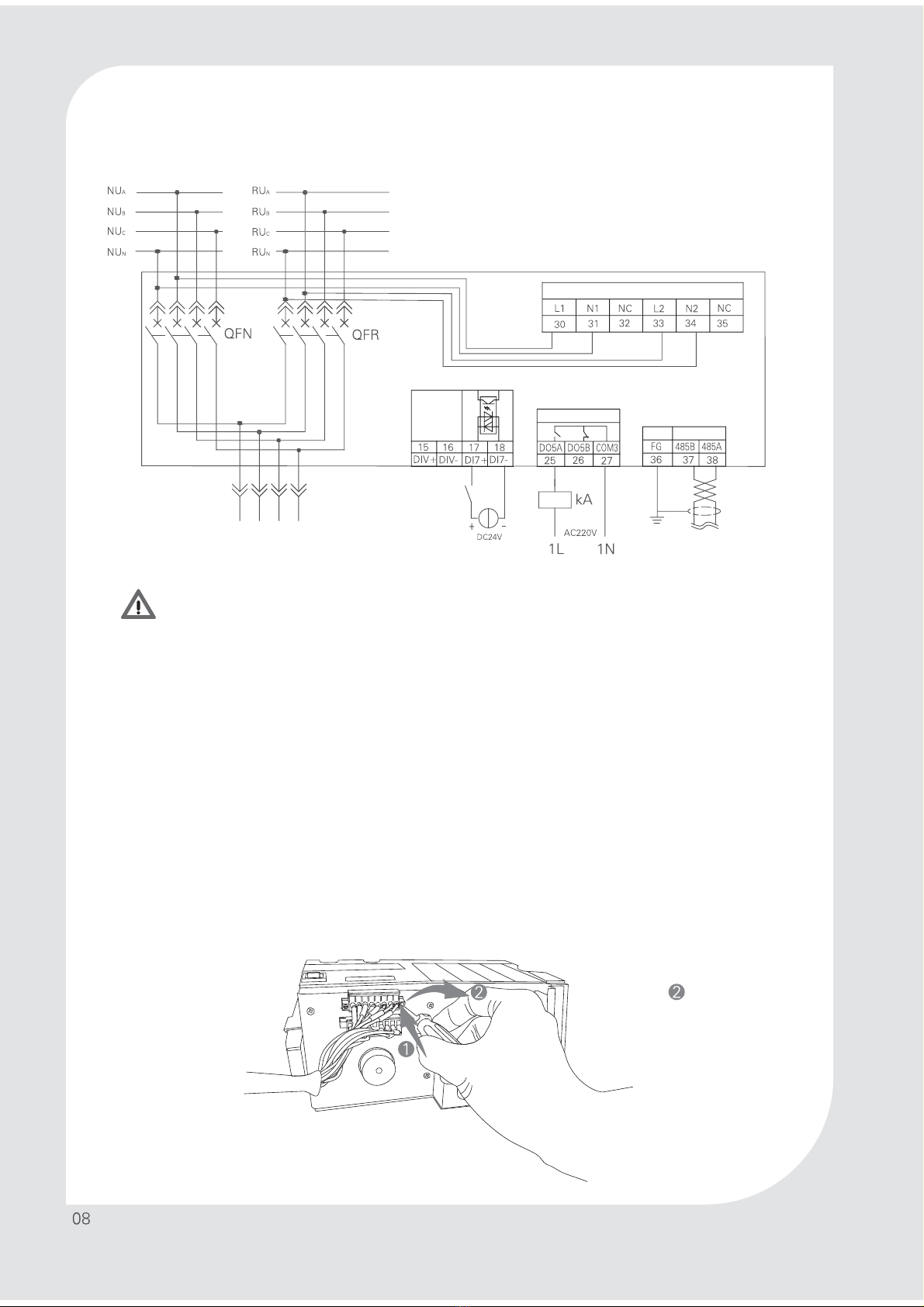
5.2.3 Mode of internal power supply
Main power Spare power
Output power
NoteĹ
NoteĹ
Input of fire blocking signal
Output of generator signal
Communication port
Noteĺ
NoteĻ
Noteĺ
kA: intermediate relay
Warning
NoteĹ: Three-pole product needs to be connected to neutral lines (N-line), with the N-line of
main power to the terminal “NUN” and N-line of spare power to “RUN”.
Noteĺ: With AC220V power supply, the controller must not be connected to an external supply
if it is powered internally.
NoteĻ: The maximum voltage for generator output terminals is AC270V/DC30V. At the maximum
voltage, the output current must not exceed 1 A.
5.3 Connection between equipment and its controller
Connection instructions
1. The connection between equipment and its controller is of plug-in type. Take out wires from the
accessory bag, and securely connect them to the screws on both sides of a terminal block according to the
terminal number.
2. Before pulling or inserting wires from or into terminal, make sure the fastening screws on the terminal
block are loosened. Do not force wires into or out of terminal block.
(1) Rotate clockwise for
fastening screws;
(2) Rotate counterclockwise for
removing screws.
Note steps:
Terminal screw: M2.5
Torque: 0.4 Nm
Input of auxiliary power supply

VI. Operating conditions
6.1 Normal operating conditions
Ambient temperature: -5ć~+40ć, not greater than +35ćon average in 24h
Altitude: not greater than 2,000 m
Atmospheric condition: The relative humidity shall not exceed 50% at ambient air
temperature of +40℃; it can be higher than 50% at lower temperatures. In the wettest
month, the monthly average relative humidity is 90% as a maximum, and +20℃as a
minimum. Special measures are required for occasional condensation due to
temperature variations.
Pollution degree: 3
Installation category: III
6.2 Usage class
6.3 Standards

VII. Technical parameters
Model and specification
Electrical grade
Standard
Number of poles
Electrical performance
Switch operating position
Service life
Service life
(with maintenance)
Minimum switch time
Mechnical
Electrical
Controller
Type A (economical)
Type B (basic)
Type D (smart)
Control voltage
Installation and connection
Fixing/connection at the panel front
Auxiliary device for monitoring and indication
Fire linkage function
Alarm feedback signal
Position feedback signal
Standard Optional Unavailable
Noteķ: The front must be provided with short-circuit protective
device meeting isolation requirements.
Housing current
Rated current
Rated frequency
Rated insulation voltage
Rated impulse withstand
voltage
Rated voltage
Rated short-time withstand
current
Rated conditional
short-circuit current
Connection and breaking capacity
Usge class
PC class
Three positions
IEC/EN 60947-6-1
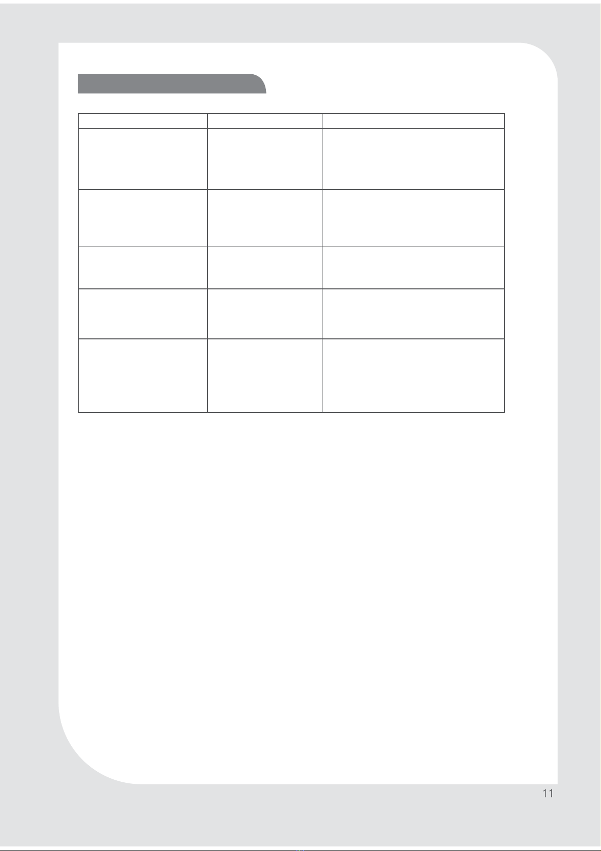
VIII. Troubleshooting of common faults
Common faults
No display on controller
The main (spare) power
indication lamp on controller
panel is not ON. The switch is at
the main (spare) power position,
and fails to act.
Failure of automatic switch
In automatic mode, the switch
fails to act upon a change to
power supply
Upon inputting a fire signal
1) The switch fails to act
2) The switch fails to return to the
previous status after its action.
Cuase
1) The controller is not
energized.
2) The terminals of connecting
wire are not securely attached
to both the transfer switch and
controller.
1) The terminals of connecting wire
are not securely attached to both
the transfer switch and controller.
2) The wires connected with the
transfer switch are loose at the
interface or come off.
The manual/auto mode is not
set correctly.
1) Both power supplies fail
2) The wires show poor
interface contact or come off
1) The fire signal wire is
improperly connected
2) The switch is set at
“manual” position.
Troubleshooting
1) Push the controller’s “power” button on
transfer switch to switch to “I” position
2) Reconnect the wire terminals as per the
steps given in Section 5.3, and secure
fastening screw
1) Reconnect the wire terminals as per the
steps given in Section 5.3, and secure
fastening screw
2) Fasten all wires connected with the switch
Push “manual/auto” button on the panel of
controller SU603 and switch to “auto” status,
in which the “auto” light is ON.
1) Provide normal main and spare power
2) Fasten all wires connected with the switch
1) Fasten all wires attached to the fire signal
terminal
2) Turn the switch to “auto” position

This document is prepared and printed by Noark,
and only covers information about this series of
products. It is subject to change at any time
without notice, for technical upgrade or application
of new technologies or for correction of misprint
and incorrect information.
Copyright©Noark Printed with eco-friendly paper
Noark Electric Europe s.r.o.
;"54/&6
Add: Sezemická 2757/2, 193 00 Praha 9, Czech Republic
Registered at Municipal Court in Prague, Section C,
Insert 181277
Tel: +420 226 203 120
Email: [email protected]
www.noark-electric.cz
This manual suits for next models
1
Table of contents


