Noise Lab FORMANTIC User manual

FORMANTIC
USER GUIDE
Technical Specification
Width: 16HP
Depth: 26 mm
Current draw: 45 mA +12V / 52 mA -12V
1

Table of contents
Technical specification 1
Getting started with your module 2
① IN A 4
② IN B 4
③ Path Switch 4
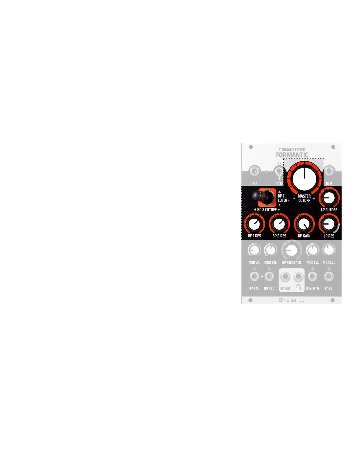
④ Master Cutoff 5
⑤ Joystick 5
⑥ LP Cutoff 5
⑦ Bandpass Resonance knobs 5
⑧ Bandpass Gain 5
⑨ Lowpass Resonance 5
⑩ CV Input (1 & 2) attenuverters (MOD LVL) 6
⑪ Bandpass Feedback 6
⑫ CV Input 3 attenuverter (MOD LVL) 6
⑬ CV Input 4 attenuator (MOD LVL) 6
⑭ Bandpass CV Inputs 6
⑮ Audio Outputs 7
⑯ BP + LP CV input 7
⑰ LP CV 7
⑱ Jumper Settings (reverse side) 7
Patching examples 8
2

Getting started with your module
1. ⚠WARNING! Always make sure your eurorack system is turned off before installing
a new module. To be on the safe side, pull the plug before you start!
2. The 10-pin connector should already be connected to your module with the red stripe
on the power cable oriented towards the white line and -12V marking.
3. Connect the free end of the power cable to the 16-pin Eurorack header on your power
supply system. The red stripe on the cable should match the white line (-12V marking)
on the bus board.
4. Attach the module to the rails of your case using the included screws.
5. Power on your Eurorack system and get started!
3

Introduction
FORMANTIC is a voltage controlled analog formant filter that combines two resonant 12dB bandpass
filters (BP) with one resonant 24dB lowpass filter (LP). Each filter has its own set of controls for
resonance and cutoff frequency. All three filters can be driven into self-oscillation.
There are two inputs. IN A routes the signal through all filters while IN B is routed through the LP filter
only. The Path switch lets you process your audio signal in series or parallel. The output signal is split
into Main Out (BP + LP) and BP Out which in turn opens up for further processing like quasi-stereo
effects etc. A unique feature of the Formantic filter is the joystick which enables intuitive interaction of
both BP filters, while the large Master Cutoff knob lets you sweep all filters simultaneously.
FORMANTIC is a free interpretation of the filter topology found in Synton's rare Syrinx synthesizer, which
was manufactured in the Netherlands in the early 1980s. However, this is not a clone; rather, our circuit is
an original Noise Lab design, engineered with numerous novel ideas that we believe set this filter apart in
many ways.
………………………………………………………..……………………………………………………………………………………….
① IN A
Input A is connected to the Path switch (see below) and routes the
signal through both BP and LP filters. Signal out via BP OUT and MAIN
OUT. The input signal is expected to be 10Vpp.
② IN B
This input is only routed via the 24dB LP filter and to the MAIN OUT.
The input signal is expected to be 10Vpp.
③ Path Switch
The PATH switch lets you process your sound through the filters in
series or parallel.
If the switch is set to the down position, the signal is routed through the
BP filters first, followed by the LP filter. In up position, the signal is split
and runs in parallel through the BP and LP filters. This has a major
impact on the sound and offers a lot of interesting ways to shape your
sound. Please note, this only applies to audio via Input A.
4
④ Master Cutoff
The big Master Cutoff knob controls the cutoff frequency for all filters.
The basic procedure is to set this knob to its center position and then
adjust the joystick and LP Cutoff knob to a desired position, then simply
sweep all filters together with the Master Cutoff.
⑤ Joystick
Finding the sweet spots between both BP filters is very easy and intuitive
thanks to the joystick control. The cutoff frequency for BP1 is set to the
Y-axis and BP2 to the X-axis.
⑥ LP Cutoff
This knob only affects the lowpass filter's cutoff frequency. As expected,
turning it clockwise opens the filter and lets all sound frequencies pass
through.
⑦ Bandpass Resonance knobs
Each BP filter has a knob to control the amount of Resonance you want.
A good starting position for both filters is a little bit past the center
position (“two o'clock”). Turning them fully to the left will increase the
internal amplitude which you might want to balance a bit by reducing the
gain. Simply lower BP Gain in order not to overdrive the LP filter.
⑧ Bandpass Gain
The BP Gain knob simply controls the signal strength into the LP filter.
Gain is usually set to max but if, for example, the BP Feedback is used
you might want to scale back the signal a bit to prevent it from getting too
saturated.
⑨ Lowpass Resonance
The LP Res knob controls the amount of resonance applied to the lowpass
filter. If no patch cord is plugged into any of the audio inputs, you can
force the filter into self-oscillation and thereby create a perfect sine wave
simply by turning up the Resonance. The pitch of the sine wave can then
be controlled via the inputs of BP 1 CV and BP 2 CV.
5

⑩ CV Input (1 & 2) attenuverters (MOD LVL)
Each bandpass filter has its own CV input and an attenuverter to control
the voltage sent to the frequency cutoff. No signal passes through the
attenuverter at its center position but as you turn the knob clockwise you
will increase the signal strength. However, by turning the knob
counterclockwise (pass the center), you’ll increase an inverted version of
the signal.
⑪ Bandpass Feedback
Control the amount of feedback applied to the bandpass filters. At higher
values the filters will start to self-oscillate and create a sine wave. The
pitch of this waveform can also be controlled via inputs of BP 1 CV and BP
2 CV or the joystick and Master Cutoff knob.
⑫ CV Input 3 attenuverter (MOD LVL)
This attenuverter controls how much voltage is passed on to both
bandpass and Lowpass filters. It actually means that you can modulate all
three filters´ cutoff frequencies using only the BP + LP CV input!
No signal passes through the attenuverter at its center position, but as
you turn them clockwise you will increase the signal strength. As you turn
the knob counterclockwise pass the center, you’ll increase an inverted
version of the signal.
⑬ CV Input 4 attenuator (MOD LVL)
This attenuator affects how much voltage is passed on to the lowpass
filter for modulation.
⑭ Bandpass CV Inputs
Each bandpass filter has a dedicated CV input. However, BP 2 CV is
normalled to BP 1 CV which means that if no patch cable is present in BP 2
CV, the signal is automatically passed on to bandpass filter 2.
6

⑮ Audio Outputs
MAIN OUT is the standard output for the filtered signal (after BP and LP
filters). BP OUT outputs the dual bandpass signal only.
⑯ BP + LP CV input
This input, as the name suggests, can control the cutoff frequencies of
all filters. It comes in handy if you for example want to use an LFO or
envelope generator to animate all filters at the same time.
Since BP1 and BP2 are internally connected (normalled) to this input, you
can break the connection by simply plugging another patch cord into
any of the inputs.
⑰ LP CV
CV input for cutoff frequency control of the lowpass filter only.
⑱ Jumper Settings (reverse side)
On the reverse side of the module, there is a jumper connector with
three options for how much of the original signal you want to hear after
passing through the BP filters. Because a fully opened bandpass filter
cuts almost all frequencies, there is very little for the low pass filter to
process. So with jumpers set to OFF, and the PATH switch set to serial,
you will hear no sound when the BP filters cutoff is fully opened.
7

Patching examples
Soon to be added here
8
Table of contents
Other Noise Lab Music Pedal manuals


