aion COMET User manual

COMET VINTAGE DISTORTION 1
PROJECT NAME
COMET
BASED ON
EFFECT TYPE
PROJECT SUMMARY
DOCUMENT VERSION
BOSS®DS-1 Distortion
A classic distortion pedal that has been in continuous production for over 40 years, blending ideas from
the Big Muff, RAT and Distortion+.
Distortion 1.0.0 (2021-10-22)
BUILD DIFFICULTY
Easy
Actual size is 2.3” x 1.86” (main board) and 2.3” x 0.86” (bypass board).

COMET VINTAGE DISTORTION 2
TABLE OF CONTENTS
1Project Overview 7Drill Template
2Introduction & Usage 8Enclosure Layout
3-4 Parts List 9Wiring Diagram
5Build Notes 10 Licensing
6Schematic 10 Document Revisions
INTRODUCTION
The Comet Vintage Distortion is a clone of the classic orange BOSS®DS-1 Distortion, one of their
earliest compact effects in continuous production since 1978.
Design-wise, the DS-1 is an amalgamation of a few different ideas. The initial transistor gain stage is
very similar to the Big Muff, as is the tone section with its bass/treble balance control. The IC gain stage
followed by diode-to-ground hard clipping is similar to early op-amp distortion circuits like the MXR
Distortion+ or Pro Co RAT.
During the past four decades, it has undergone several revisions. The basic schematic structure has
stayed the same throughout its production, but when the original IC was discontinued in the early
‘90s, the op-amp gain stage was redesigned to use a standard dual op-amp. Previously it had used a
Toshiba TA7136P special-purpose “RIAA preamp” that was technically not even a true op-amp, so this
necessitated several changes. They also re-voiced the circuit at the same time, reducing the bass and
lowering the clipping threshold slightly.
The result is that there is a significant difference between the “pre-1994” and “post-1994” versions of
the circuit. The pre-’94 version remains highly regarded, while the post-’94 circuit is responsible for the
DS-1’s reputation as a poor-quality beginner’s pedal. The good news is that the voicing changes are fully
reversible, and it’s possible to get the post-’94 dual op-amp version to sound just as good as the pre-’94
version with a handful of capacitor and diode changes.
The Comet is based on the dual op-amp version of the circuit. The default build makes a few parts
substitutions to make it nearly identical to the pre-’94 circuit. If you want to use the TA7136P chip for
an exact replica of the pre-’94 DS-1, the legacy version of the Comet is still available and supports either
configuration. However, this updated version drops support for the old IC because it’s almost impossible
to find today and the build process is much more streamlined without the option.
USAGE
The Comet has three controls and one toggle:
• Distortion controls the amount of gain from the op-amp stage that is clipped by the diodes.
• Tone pans between a bass emphasis and a treble emphasis, with a mid-scoop centered at 550 Hz.
• Level sets the overall output of the effect.
• Clipping selects between three different sets of hard-clipping diodes.

COMET VINTAGE DISTORTION 3
PARTS LIST
This parts list is also available in a spreadsheet format which can be imported directly into Mouser for
easy parts ordering. Mouser doesn’t carry all the parts—notably potentiometers—so the second tab lists
all the non-Mouser parts as well as sources for each.
View parts list spreadsheet →
PART VALUE TYPE NOTES
R1 1k Metal film resistor, 1/4W
R2 470k Metal film resistor, 1/4W
R3 10k Metal film resistor, 1/4W
R4 100k Metal film resistor, 1/4W
R5 470k Metal film resistor, 1/4W
R6 10k Metal film resistor, 1/4W
R7 22R Metal film resistor, 1/4W
R8 100k Metal film resistor, 1/4W
R9 47k Metal film resistor, 1/4W
R10 100k Metal film resistor, 1/4W
R11 4k7 Metal film resistor, 1/4W
R12 2k2 Metal film resistor, 1/4W
R13 6k8 Metal film resistor, 1/4W
R14 2k2 Metal film resistor, 1/4W
R15 6k8 Metal film resistor, 1/4W
R16 10k Metal film resistor, 1/4W
R17 1M Metal film resistor, 1/4W
R18 10k Metal film resistor, 1/4W
R19 1k Metal film resistor, 1/4W
R20 100k Metal film resistor, 1/4W
R21 10k Metal film resistor, 1/4W
R22 10k Metal film resistor, 1/4W
R23 100R Metal film resistor, 1/4W
RPD 2M2 Metal film resistor, 1/4W Input pulldown resistor.
LEDR 4k7 Metal film resistor, 1/4W LED current-limiting resistor. Adjust value to change LED brightness.
C1 47n Film capacitor, 7.2 x 2.5mm
C2 47n Film capacitor, 7.2 x 2.5mm
C3 250pF Ceramic capacitor, X5F
C4 OMIT Use 100n for the Big Muff clipping mod. Leave empty otherwise.
C5 68n Film capacitor, 7.2 x 2.5mm
C6 100pF MLCC capacitor, NP0/C0G
C7 470n Film capacitor, 7.2 x 3mm

COMET VINTAGE DISTORTION 4
PARTS LIST, CONT.
PART VALUE TYPE NOTES
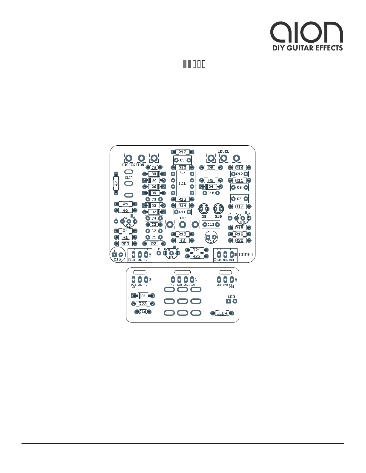
C8 470n Film capacitor, 7.2 x 3mm
C9 10n Film capacitor, 7.2 x 2.5mm
C10 22n Film capacitor, 7.2 x 2.5mm
C11 100n Film capacitor, 7.2 x 2.5mm
C12 47n Film capacitor, 7.2 x 2.5mm
C13 1uF Film capacitor, 7.2 x 3.5mm
C14 47uF Electrolytic capacitor, 5mm Reference voltage filter capacitor.
C15 100uF Electrolytic capacitor, 6.3mm Power supply filter capacitor.
C16 100n MLCC capacitor, X7R Power supply filter capacitor.
D1 1N5817 Schottky diode, DO-41
D2 OMIT Use 1N914 for the Big Muff clipping mod. Leave empty otherwise. See
build notes for more info.
D3 OMIT
D4 1N914 Fast-switching diode, DO-35
D5 1N914 Fast-switching diode, DO-35
D6 BAT46 Schottky diode, DO-35
D7 1N914 Fast-switching diode, DO-35
D8 BAT46 Schottky diode, DO-35
D9 3mm LED LED, 3mm, red diffused
D10 3mm LED LED, 3mm, red diffused
Q1 2N5088 BJT transistor, NPN, TO-92 Substitute. Original uses 2SC2248.
Q2 2N5088 BJT transistor, NPN, TO-92 Substitute. Original uses 2SC2248.
Q3 2N5088 BJT transistor, NPN, TO-92 Substitute. Original uses 2SC2248.
IC1 NJM3404AD Operational amplifier, DIP8 Can substitute JRC4580D.
IC1-S DIP-8 socket IC socket, DIP-8
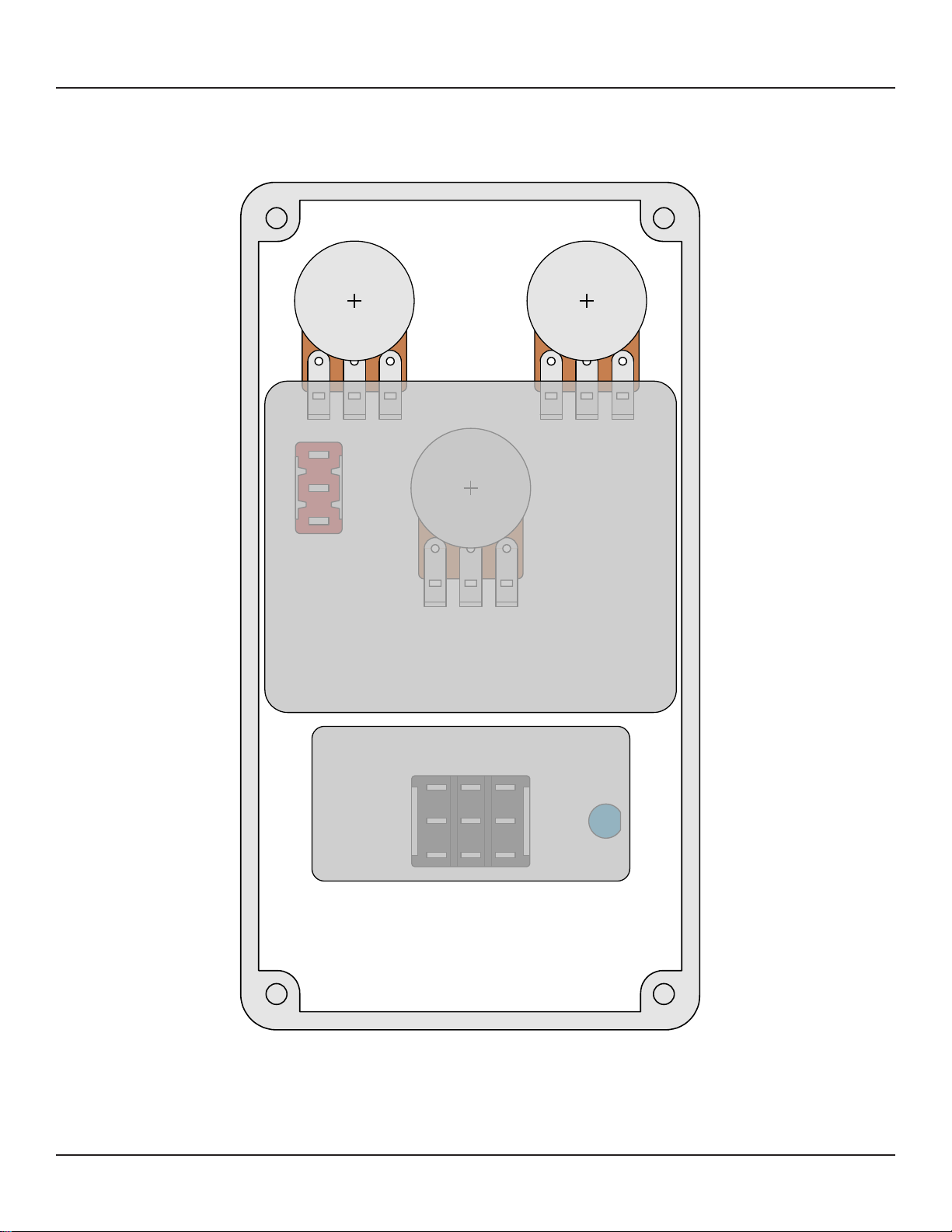
DIST. 100kB 16mm right-angle PCB mount pot
TONE 25kB 16mm right-angle PCB mount pot The original uses 20kB if you can find it, but 25kB is much more common
and will work the same.
LEVEL 100kB 16mm right-angle PCB mount pot
CLIP SPDT cntr off Toggle switch, SPDT center off
LED 5mm LED, 5mm, red diffused
IN 1/4" stereo 1/4" phone jack, closed frame Switchcraft 112BX or equivalent.
OUT 1/4" mono 1/4" phone jack, closed frame Switchcraft 111X or equivalent.
DC 2.1mm DC jack, 2.1mm panel mount Mouser 163-4302-E or equivalent.
BATT Battery snap 9V battery snap Optional. Use the soft plastic type—the hard-shell type will not fit.
FSW 3PDT Stomp switch, 3PDT
ENC 125B Enclosure, die-cast aluminum Can also use a Hammond 1590N1.

COMET VINTAGE DISTORTION 5
BUILD NOTES
Pre-1994 version
The default parts list for the Comet is for the pre-1994 version, the only difference being the op-amp
since the original TA7136P IC is no longer produced and very hard to find. This involves changing three
capacitors (C5, C6 and C7).
The original diodes clipped near 1V, but since no equivalents are readily available, it’s recommended to
use 1N914 (0.65V) and BAT46 (0.35V) in series for each diode pair. The “stock” clipping mode is the up
position of the toggle switch, and the down position is a little more compressed and lower volume.
Pre-1994 version
If you’d like to build the post-1994 version of the DS-1, make the following substitutions:
• C5: 470n →68n
• C6: 250pF →100pF
• C7: 1uF →470n
Additionally, the “stock” clipping mode is now the down position of the toggle switch. You can change
out D6 and D8 for normal 1N914 diodes to raise the clipping threshold a little bit, providing more
contrast between the up and down positions.
IC selection
The DS-1 has undergone a few other minor circuit changes after the major revision in 1994, mostly
related to the IC:
• 1994-2000: Rohm BA728N
• 2000-2006: Mitsubishi M5223AL
• 2006-2016: New Japan Radio NJM2904L, later changed to NJM3404L, exact year unknown
• 2016-present: New Japan Radio NJM4580 (JRC4580)
The first four are single-in-line (SIL) dual op-amps, although the NJM2904 and NJM3404 have a DIP-8
version available. Since 2016 when BOSS made the switch to SMD, the DS-1 has used the JRC4580. It’s
recommended to use either the NJM3404 or NJM4580 in this project.
Big Muff clipping mod
The amplifier stage formed by Q2 is identical to the first transistor stage of the Big Muff. The stock DS-1
does not have any clipping in this stage, but if you want to experiment, space has been provided to add
the two diodes and capacitor and convert it into something more like stage 2 or 3 of the Big Muff with
feedback diode clipping.
To try this modification, use 1N914 for D2 and D3 and a 100n film capacitor for C4. Omit these three
parts for the stock DS-1 circuit.

SCHEMATIC
COMET VINTAGE DISTORTION 6
GND
2M2
1N5817
100uF
100kB
GND
100kB
25kB
+9V
100n
VA
100R 10k
10k
VB
47uF
GND GND
1k
47n
470k
VB
2N5088
VA
10k
47n
100k
GND GND
2N5088
470k
250pF
OMIT
10k
VA
22R
GND
470n
100k
47k
1N914
GND
VA
GND
100k
250pF
4k7
1uF
GND
2k2
470n
10n
6k8
22n
2k2
6k8
100n
10k
47n
1M
VB
2N5088
VA
10k
1k
1uF
GND
100k
GND
VB
VB VB
VB
VB
VB
VB
IN
OUT
RPD
D1
C15
1
2
3
DISTORTION
LEVEL
1
2
3
TONE
1
2
3
C16
R23 R21
R22
C14
R1
C1
R2
Q1
R3
C2
R4
Q2
R5
C3
C4
D2
D3
R6R7
C5
R8
R9
D4
IC1B
6
5
7
84
NJM3404AD
IC1A
2
3
1
R10
C6
R11
C7
R12
C8
D5D6
D7D8
D9
D10
CLIP
2
3
1
C9
R13
C10
R14
R15
C11
R16
C12
R17
Q3
R18
R19
C13
R20
GND

COMET VINTAGE DISTORTION 7
DRILL TEMPLATE
Cut out this drill template, fold the edges and tape it to the enclosure. Before drilling, it’s recommended
to first use a center punch for each of the holes to help guide the drill bit.
Ensure that this template is printed at 100% or “Actual Size”. You can double-check this by measuring
the scale on the printed page.
Top jack layout assumes the use of closed-frame jacks like the Switchcraft 111X. If you’d rather use
open-frame jacks, please refer to the Open-Frame Jack Drill Template for the top side.
LED hole drill size assumes the use of a 5mm LED bezel, available from several parts suppliers. Adjust
size accordingly if using something different, such as a 3mm bezel, a plastic bezel, or just a plain LED.
x: -0.65, y: +1.71 x: 0.65, y: +1.71
ø9/32” ø9/32”
x: 0, y: +0.66
ø9/32”
x: 0, y: -1.20
ø15/32”
x: -0.775, y: -1.20
ø5/16”
CENTER (0,0)
ø3/8” ø1/2”
0.385”
0.625” 0.625”
ø3/8”
OUT DC IN
125B
VOLUME
CLIPTONE
DISTORTION
FOOTSWITCHLED
x: +0.85, y: +0.66
ø1/4”
0 1 2
CM
0 1
INCH

COMET VINTAGE DISTORTION 8
ENCLOSURE LAYOUT
Enclosure is shown without jacks. See next page for jack layout and wiring.
125B

COMET VINTAGE DISTORTION 9
WIRING DIAGRAM
125B
IN +VGND N.C. N.C. OUT
PCB
IN
GND +V +V JACK GND JACK
OUTIN
GND GND PCB
OUT
Shown with optional 9V battery. If battery is omitted, both jacks can be mono rather than one being stereo.
Leave the far-right lug of the DC jack unconnected.

COMET VINTAGE DISTORTION 10
LICENSE & USAGE
No direct support is offered for these projects beyond the provided documentation. It’s assumed
that you have at least some experience building pedals before starting one of these. Replacements and
refunds cannotbe offered unless it can be shown that the circuit or documentation are in error.
All of these circuits have been tested in good faith in their base configurations. However, not all the
modifications or variations have necessarily been tested. These are offered only as suggestions based
on the experience and opinions of others.
Projects may be used for commercial endeavors in any quantity unless specifically noted. No
attribution is necessary, though a link back is always greatly appreciated. The only usage restrictions
are that (1) you cannot resell the PCB as part of a kit without prior arrangement, and (2) you cannot
“goop” the circuit, scratch off the screenprint, or otherwise obfuscate the circuit to disguise its source.
(In other words: you don’t have to go out of your way to advertise the fact that you use these PCBs, but
please don’t go out of your way to hide it. The guitar effects industry needs more transparency, not less!)
DOCUMENT REVISIONS
1.0.0 (2021-10-22)
Initial release.
Table of contents
Other aion Music Pedal manuals

aion
aion ZIRCON SILICON FUZZ User manual

aion
aion DEIMOS User manual

aion
aion TEMPEST User manual

aion
aion Nimbus User manual

aion
aion PLASMA VINTAGE DRIVE User manual

aion
aion STRATUS User manual

aion
aion PROCYON User manual

aion
aion Fusion User manual

aion
aion theseus User manual

aion
aion PROCYON User manual

aion
aion Cadmus User manual

aion
aion Minima User manual

aion
aion CRESCENT AMP DISTORTION User manual

aion
aion TITAN User manual

aion
aion ASTRA SILICON FUZZ User manual

aion
aion SOMNUS User manual

aion
aion CHROMA User manual

aion
aion STRATUS User manual

aion
aion HALO User manual

aion
aion TRITON MK. III User manual