NoiseKen ISS-7630-CUP User manual

R
INSTRUCTIONMANUAL
COUPLING CLAMP
MODEL
ISS-7630-CUP
Noise L a boratory Co., Ltd.
Edition 1.01
AEJ00362-001-0B

NOTICE
•
The contents of this instruction manual(the “Manual”)are subject to change without
prior notice.
•
No part of the Manual may be reproduced or transferred, in any form and for any
purpose, without the permission of Noise Laboratory Co., Ltd.(the “Company”).
•
The contents of the Manual have been thoroughly examined. However, if you find
any problems, misprints, or missing information, please contact our sales agent who
you purchased our product from.
•
The Company assumes no responsibility for any loss or damage resulting from
improper usage, failure to follow this manual, or any repair or modifications of this
product undertaken by a third party other than the Company or the agent authorized
by the Company.
•
The Company assumes no responsibility for any loss or damage resulting from
remodeling or conversion solely undertaken by the user.
•
Please note that the Company cannot be held responsible for any consequences
arising from the use of this product.
•
Product names and business names referred to in this manual are generally
trademarks or registered trademarks of third parties. And those trademarks have
nothing to do with the Company. ® and TM are not always referred to in this
manual.

1
1. IMPORTANT
SAFETY PRECAUTIONS
The following instructions are very important for safe handling of ISS-7630-CUP
(the “Unit”). Read them carefully before use.
1. Do not use the Unit near flammable materials or fire sources. When
used, there is a risk of fire due to pulses, etc
2. Any person with medical electronics such as a heart pacemaker is not
to operate the Unit. And, do not enter the test area while the Unit is
operating.
3. To avoid electric shock, be sure that the power of the Unit, the power
source, and the device under test ("DUT") are all turned OFF, and make
sure there is no residual voltage before making any connections.
4. A number of safety recommendations are listed in the later chapter
"BASIC SAFETY PRECAUTIONS". Be sure to read them before test
environment settings, connecting and testing.
5. A powerful magnetic field is generated by the Unit at the time of pulse
output. Give careful consideration to your testing environment to use
the Unit.

2
Memorandum

3
2.
A
PPLICATION
F
ORM INSTRUCTION
M
ANUAL
We place an order for an instruction manual.
Model: ISS-7630-CUP
Serial No.:
Applicant:
Company name:
Address:
Department:
Person in charge:
Tel No.:
Fax No.
Cut off this page “APPLICATION FORM FOR
INSTRUCTION MANUAL” from this volume and keep it
for future use with care.
When an INSTRUCTION MANUAL is required, fill in the above Application
Form and mail or fax it to the following sales department of our company.
To: Noise Laboratory Co., Ltd.
1-4-4 Chiyoda Sagamihara City,
Kanagawa Pref., 229-0037 Japan
Tel: +81-(0)42-712-2051 Fax: +81-(0)42-712-2050
Cut
line

4
Memorandum

5
3. CONTENTS
1. IMPORTANT SAFETY PRECAUTIONS..........................................................................1
2. APPLICATION FORM INSTRUCTION MANUAL............................................................3
3. CONTENTS.....................................................................................................................5
4. PREFACE........................................................................................................................6
5. BASIC SAFETY PRECAUTIONS....................................................................................7
5-1.
S
YMBOLS OF
H
AZARD
.........................................................................................................7
5-2.B
ASIC
S
AFETY
P
RECAUTIONS
...........................................................................................7
5-3.
L
OSS OF
W
ARNING
L
ABEL
..................................................................................................8
6. MAIN FEATURES ...........................................................................................................9
6-1.
F
EATURES
..........................................................................................................................9
6-2.
R
EGARDING
ISO7637-3
(1995-07-15) ...............................................................................9
7. PART NAMES AND FUNCTIONS.................................................................................10
8. TEST PROCEDURE......................................................................................................12
8-1.
T
EST
P
REPARATION
.........................................................................................................12
8-2.
R
UNNING
DUT .................................................................................................................13
8-3.
S
TARTING
T
EST
................................................................................................................13
8-4.
F
INISHING
T
EST
................................................................................................................13
9. PRODUCT SPECIFICATIONS ......................................................................................14
10. WAVEFORM VERIFICATION......................................................................................15
11. ACCESSORIES...........................................................................................................16
12. OPTIONS.....................................................................................................................17
13. WARRANTY................................................................................................................18
14. MAINTENANCE ..........................................................................................................20
15. NOISE LABORATORY SUPPORT NETWORK ..........................................................21

6
4. PREFACE
Thank you very much for purchasing ISS-7630-CUP (the "Unit"). Please read this instruction manual
(the "Manual") thoroughly prior to use of the Unit in order to attain the maximum and safe use of the
Unit.
The Manual will let you operate ISS-7630-CUP safely and make the most use of it if
you strictly follow the operational procedures and the safety instructions.
Keep the Manual handy whenever you operate ISS-7630-CUP.

7
5.
B
ASIC
S
AFETY
P
RECAUTIONS
5-1. Symbols of Hazard
This sign indicates the presence of "dangerous voltage/current" that may endanger
persons.
This sign indicates "handle with care".
Refer to the Manual to protect human bodies and devices.
5-2.Basic Safety Precautions
1. There is a risk of electric shock.
【Precautions regarding use and safety】
2. Do not supply the Unit with voltage or do not make any connections other than the
designated load (Accessory Terminator). The Unit may be damaged if this is not
obeyed
【Precautions regarding connection and use】
3. Before connecting the Unit, turn OFF the DC power source and the Unit, and make
sure that there is no residual voltage. Connect each cable securely. Nonobservance
may cause electric shock or damage to the internal parts of the Unit and connected
devices.
【Precautions regarding bodily injury and connection】
4. Use accessories and optional items supplied by the Company to ensure safe
operation.
【Precautions regarding connection and use】
5. Do not utilize or store the Unit under extremely high or low temperature
environment. (Operating environment: 23℃±5℃/ Operating Humidity Range:
25-75 %)
【Precautions regarding environment】
6. Do not use the Unit under high humidity or dusty conditions.
【Precautions regarding environment】
7. Should condensation form, fully dry the Unit before usage.
【Precautions regarding environment】
8. Do not wipe the body of the Unit with solvents such as lacquer thinner or alcohol.
When the Unit gets dirty, wipe it with a detergent moistened fabric etc.
【Precautions regarding use】
9. Do not use the Unit near flammable materials or fire sources. When used, there is a
risk of fire due to electric discharge, etc.
【Precautions regarding bodily injury and environment】

8
10. The Company and its sales agent assume no responsibility for any bodily injury,
loss, damage or resultant damage arising from derelict misuse of the Unit on the
part of the user.
【Precautions regarding bodily injury, use, environment, and connection】
11. Should the necessity of services such as repair, maintenance, or internal calibration
arise, leave them to qualified service personnel only.
【Precautions regarding use and safety】
5-3. Loss of Warning Label
1. If the warning label is peeled off and missing or it gets dirty, replace it with a new one for
safety.
2. If the warning label is lost, order a new one from our sales agent or the technical service
center of the Company.
9
6
. MAIN FEATURES
6-1. Features
This coupling clamp, ISS-7630-CUP (the “Unit”) complies with the ISO7637-3 (1995-07-15)
Standard.
The Unit allows easy testing when connected to pulse simulator (ISS-7630 or ISS-P3ab).
The Unit has a micro-strip line structure, and the characteristic impedance is 50Ω.
The waveform is not distorted because of well matched impedance..
The Unit is capable of handling fast rising waveforms of tr <3.5ns input from the pulse
simulator ISS-7630.
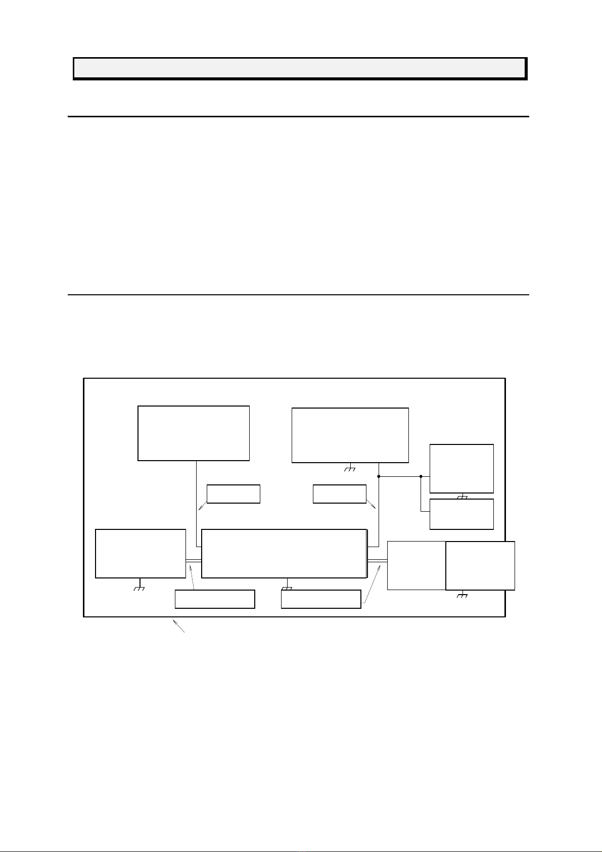
6-2. Regarding ISO7637-3 (1995-07-15)
ISO 7637-3 (1995-07-15) provides the standard for coupling tests. It specifies configuration of
the tests, pulse voltage waveform, test voltage level, and testing environment. The Unit is
designed in compliance with the ISO standard. Summary of the schematic circuit diagram
excerpted from the standard is shown below. Be sure to refer to the ISO standard for details.
供試機器
(ECU or EUT)
周辺装置
(センサ、負荷、装備品)
ATT(40dB)
50Ω
オシロ
50Ω
カップリング・クランプ
試験器
(ISS-7630,
ISS-P3ab)
バッテリ
DC電源
又は50Ωターミネータ④
同軸ケーブル③同軸ケーブル②
ハーネス ハーネス
グランドプレーン(2m × 1m以上 t=1mm以上)
Figure 1 Testing Configuration (for Coupling Clamp Tests)
Figure 1 is a schematic diagram. Run tests in accordance with the IS0 tandard or a test plan.
Harness Harness
ECU or DUT Peripheral
Equipment
Simulator
(ISS-7630,
ISS-P3ab)
Coupling clamp
Or 50Ω
Terminator
DC
Power
Supply
Battery
Oscilloscope
50Ω
ATT
(40dB)
50
Ω
Coaxial cable②Coaxial cable③
Ground plane (size: more than 2m x 1m, thickness: more than 1mm)

10
7. PART NAMES AND FUNCTIONS
② ① ③ ④
Figure 2
①Coupling Clamp
②Coaxial Connection Cable for a simulator.
③Coaxial Connection Cable for a terminator.
④Terminator
11
①Coupling Clamp
The coupling clamp main unit for coupling pulses to harnesses etc.
The unit is utilized by inserting a harness into the plates of the clump located on the
ceiling.
Stray capacity arisen between the harness and the plate transmits the high
frequency components onto the secondary side (harnesses) mainly by electrostatic
inductions. Therefore, the transmission gets harder as the noise components reach
a lower frequency range.
Since the transmission efficiency depends on the stray capacity between the
harness and the plate, the harness should be pinched by the plates as tight as
possible to increase the stray capacity.
The coupling would not take effect unless the coupling pulses have sufficient
energy of high frequency range.
Do not touch any portion of the clamp during pulse output. Otherwise you may get an
electric shock.
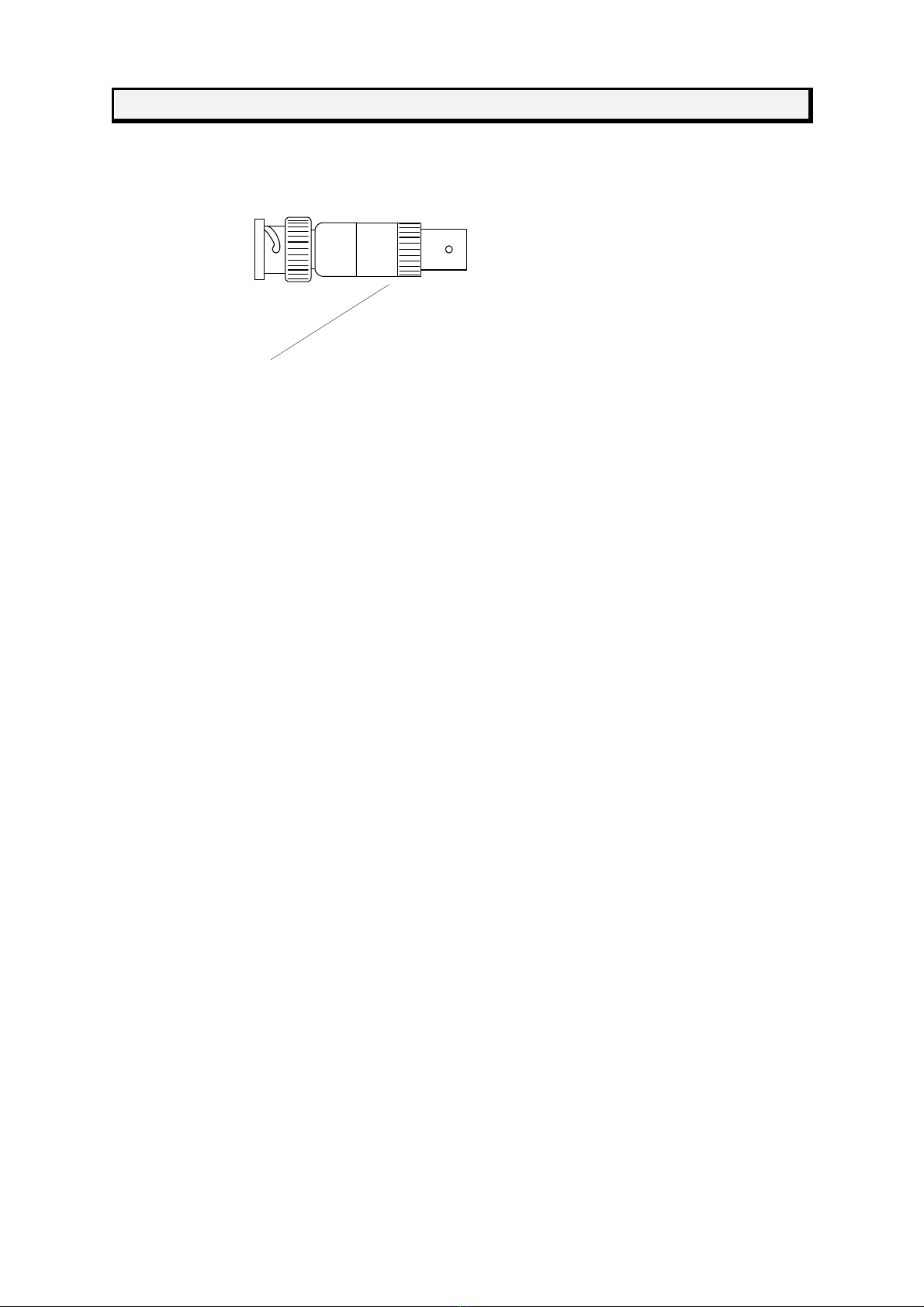
②Coaxial Cable (For Simulator Connection)
This is a 50Ωcoaxial cable with BNC connectors to connect the coupling clamp to
the simulator.
A BNC tangent line is attached.
One end is to be connected to the pulse simulator (ISS-7630 or ISS-P3ab), and the
other end is to be connected to the terminator.
③Coaxial Cable (For Terminator Connection)
A 50Ωcoaxial cable with BNC connectors to connect the coupling clamp to the
attached terminator
One end is to be connected to the coupling clamp, and the other end is to be
connected to the terminator.
④Terminator
A 50Ωterminal resistor for matching the transmission line (coupling clamp) with
50Ω.
The rated power of the terminator is 5W. Take every caution not to input the voltage
that gives higher effective power than the rating. In case of coupling pulses of the
ISS 7630 simulator or ISS-P3ab without DC voltage, It will be no problem.
⑤ Metal Fasteners
Metal pieces to fasten the simulator (ISS-7630) to the ground plane.
Attach them to 2 locations, at the FG terminals on the front and rear panes.
Refer to “8.1 Preparation of Testing”.

12
8. TEST PROCEDURE
8-1. Test Preparation
Before proceeding with the test, always carry out “10 Pre-Start Checkup (Waveform Verification).”
Prepare the installation environment and connect the cables. Set up according to the Standard
and/or other user requirements. An example is shown below.
・Installation
Place the Coupling Clamp, the simulator (ISS-7630 or ISS-P3ab), an
oscilloscope, and the power source (batteries) on the ground plane, and
secure each with screws. Use the Metal Fasteners attached to ISS-7360-Cup
to secure ISS-7630.
BNC変換アダプタ
(ISS-7630の添付品)
試験器固定金具⑤
(フロントパネル用)
試験器固定金具⑤
(リアパネル用)
Set DUT, peripheral DUT connecting devices, the harness.
・Wiring the Simulator (for ISS-7630)
Insert the BNC Conversion Adapter (accessory to ISS-7630) into the output connector
(DC LINE OUT/PULSE). Connect the BNC Conversion Adapter and the Coupling
Clamp ①with Coaxial Cable ②. Connect the Coupling Clamp ①and the Terminator
④with Coaxial Cable ③. In case of evaluating the waveform after passing the
Coupling Clamp, connect 20dB ATT in two series instead of the Terminator ④and
examine the waveform using an oscilloscope (50Ωtermination) after the 40dB
attenuation.
・Wiring the Simulator (for ISS-P3ab)
Connect the ISS-P3ab simulator’s Surge OUT BNC connector (Coupling Clamp) and
the Coupling Clamp ①with Coaxial Cable ②. Connect the Coupling Clamp ①and
the Terminator ④with Coaxial Cable ③. When evaluating the waveform after passing
the Coupling Clamp, connect 20dB ATT in two series instead of the Terminator ④and
examine the waveform using an oscilloscope (50Ωtermination) after the 40dB
attenuation.
・Connecting DUT
Connect DUT and peripheral connecting devices.
Insert the harness of DUT and the peripheral devices into the clamper portion
of the Coupling Clamp ①.
BNC conversion adaptor
(Accessory of ISS-7630)
Metal fittings to
fix the simulator
Metal fittings to fix
the simulator
13
Since the waveform contains high frequency components over the range of 200MHz, the
malfunction level cannot be measured quantitatively if the free capacity and the
electromagnetic field radiation deviate due to placement of the simulator and DUT,
types of cables used, and the height from ground plane. This highly depends on the
physical positioning of devices under the testing environment. Thus, devices must be
always positioned in the same locations in order to realize quantitative tests.
8-2. Running DUT
Run DUT as it is used. Input signals preliminarily if necessary.
8-3. Starting Test
When the simulator (ISS-7630, ISS-P3ab) begins to output pulses, the pulse is coupled to the
harness.
Proceed according to the Standard or test plan.
For operation procedures of the simulator, refer to its manual.
Do not touch the clamper portion on the ceiling when outputting pulse. There is a risk of electric
shock.
The Terminator may burn out when tests are carried out coupling pulses to DC.
Always couple pulses without DC voltage.
To avoid coupling pulses to DC, be sure to turn OFF the DC LINE of ISS-7630. As for ISS-P3ab,
always connect from the Surge OUT BNC connector (Coupling Clamp).
Since the waveform contains high frequency components over the range of 200MHz, the
malfunction level cannot be measured quantitatively if the free capacity and the
electromagnetic field radiation deviate due to placement of the simulator and DUT,
types of cables used, and the height from ground plane. This highly depends on the
physical positioning of devices under the testing environment. Thus, devices must be
always positioned in the same locations in order to realize quantitative tests.]
8-4. Finishing Test
To finish the test using ISS-7630, put it in STOP mode. As for ISS-P3ab, lower the
simulator output voltage to 0V and then put it into STOP mode.
Next, turn the power OFF.
Stop the operation (working status) of DUT, and shut the power supply off.
Remove the harness from the coupling clamp.

14
9. PRODUCT SPECIFICATIONS
・Coupling Harness Measurements····························· 4mm~40mm Diameter
・Pulse Voltage Insulator Strength ······························ over 600V
・VSWR (without Harness) ········································ less than 1.3 (~200MHz)
・Input/Output Connector ·········································· BNC-R
・Dimensions·························································· (approximately)
1200mm×H70mm×D300mm
・Weight ································································ (approximately) 3.5kg
・Terminator ··························································· 50Ω±5Ω
5W
・Run Time Temperature ·········································· 23ºC±5ºC
・Run Time Humidity ················································ 25%~75%
15
10. WAVEFORM VERIFICATION
Before proceeding to the coupling clamp tests, confirm that the simulator is transmitting pulses
normally. Refer to Figure 1. However, when verifying the waveform, harness must not be inserted
into the clamper portion. Insertion of the harness will alter the characteristic impedance and
cause reflections onto the waveform. The ISO complied procedure for waveform
verification is given below. Refer to ISO Standards for details.
・Place Coupling Clamp, the simulator (ISS-7630 or ISS-P3ab), and an oscilloscope on the
ground plane and screw fasten. Use Metal Fasteners ⑤for ISS-7630.
・Wiring the Simulator (for ISS-7630)
Insert the BNC Conversion Adapter (ISS-7630 accessory) into Output Connector (DC LINE
OUT/PULSE).
Connect the BNC Conversion Adaptor and Coupling Clamp ①with Coaxial Cable ②.
Connect the Coupling Clamp ①and 20dB ATT×2 (2 connected in series to attenuate 40dB) with
Coaxial Cable ③.
Connect 20dB ATT to oscilloscope (50Ωtermination) and verify the waveform.
・Wiring the Simulator (for ISS-P3ab)
Connect the simulator ISS-P3ab Surge Out BNC connector (Coupling Clamp) and Coupling Clamp
①with Coaxial Cable ②.
Connect the Coupling Clamp ①and 20dB ATT×2 (2 connected in series to attenuate 40dB) with
Coaxial Cable ③.
Connect 20dB ATT to oscilloscope (50Ωtermination) and verify the waveform.
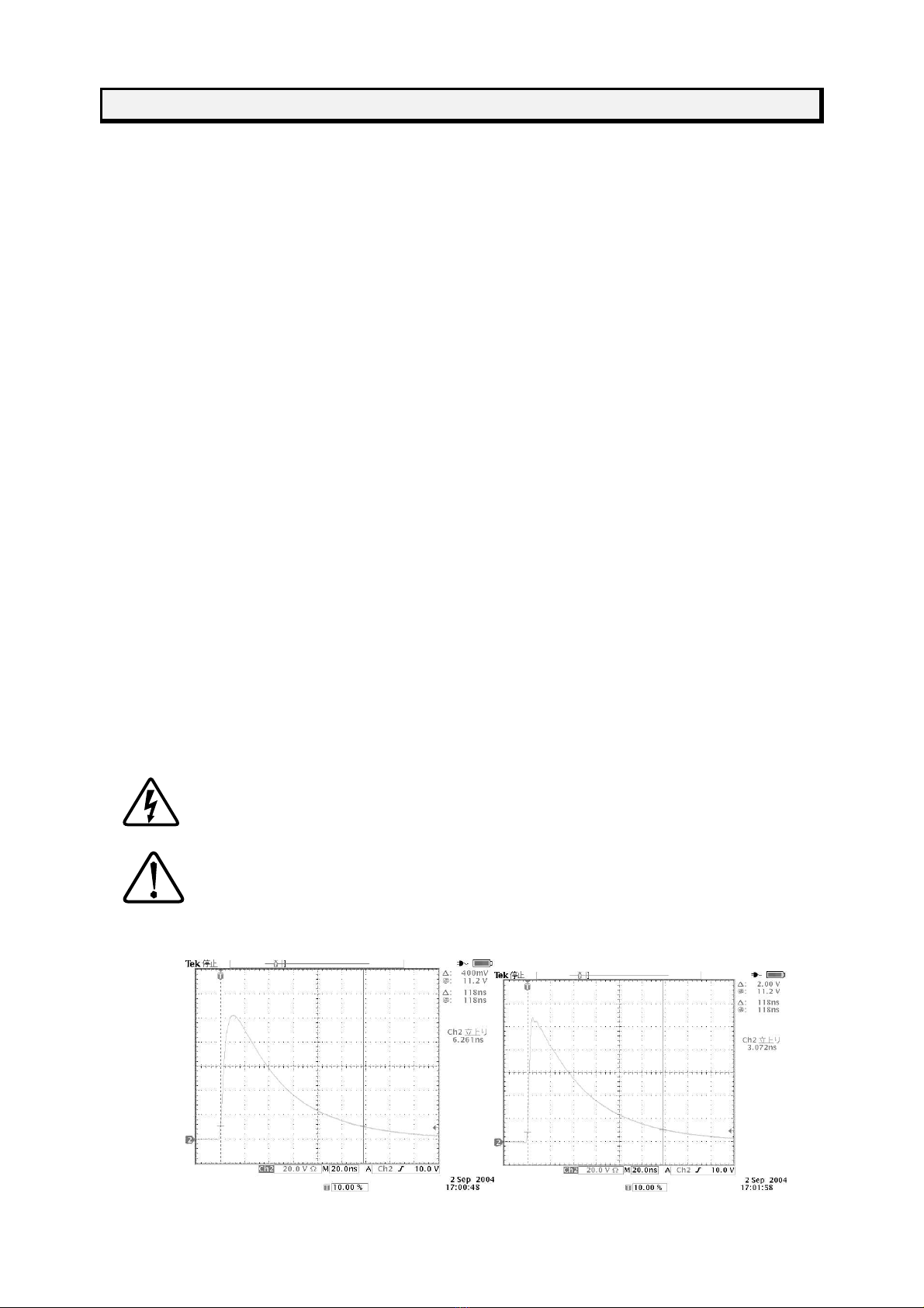
・Output pulses from the simulator and verify that the oscilloscope waveform matches the 50Ωload
waveform shown in the specifications of the simulator.
Do not touch the clamper portion of the ceiling when outputting pulse.
There is a risk of electric shock.
The Terminator may burn out when tests are carried out coupling pulses to DC.
Always verify the waveform without DC injection.
Measured Waveforms (After Passing Coupling Clamp) tr < 3.5ns Setting

16
11. ACCESSORIES
Bag of
Accessories
Instruction
Manual
Coaxial Cable ①
(To Connect with Simulator)
Coaxial Cable②
(To connect to Terminator) Terminator ③
Metal Fittings ⑤(for ISS-7630)
フロントパネル用
リアパネル用
For front panel
For rear panel
17
12.
O
PTIONS
50ΩLoad Waveform Verification ATT 00-00006A
20dB 50Ω
20dB ATT Set of 2

18
13. WARRANTY
Services
The following terms are applicable to the services provided by the Company to maintain and
repair the Unit.
1.
Scope
The Unit and accessories and options provided by the Company are covered under this
section.
2.
Technical Service Fee
Any repairs provided by the Company during the warranty period will be free of charge in
accordance with the Limited Warranty. After expiration of the warranty period, actual cost
for the repair will be charged to the user.
3. Ownership of Defective Parts
All the defective parts replaced during the warranty period become the property of the
Company. For paid repairs, they also become the property of the Company unless
otherwise directed by the user.
4. Maximum Compensation
In the event the user incurs damage due to malfunction of the Unit arising solely from the
negligence and/or improper repair on the part of the Company, the Company will
compensate for the damage. The maximum compensation amount shall be limited to the
amount paid by the user at the time of purchase of the Unit. In no event, shall the company
be liable or in any way responsible for incidental or consequential damages such as loss of
profit or third party’s claims to the user.
5. Wrong Parts, Missing Parts and Damage
The company shall not be liable for loss of profit, business interruption, other incidental
damage, special loss, punitive damage or third party’s claims to the user directly or
indirectly arising from suspension of testing activities due to wrong parts, missing parts, or
damage of the Unit.
6. Service Refusal
The company may not accept a repair order in the following cases:
More than 5 years have passed since the product discontinued
More than 8 years have passed after delivery
Required component for servicing already discontinued and no alternative is available.
Product changed, repaired or remodeled without obtaining a prior permission from the
Company.
Product severely damaged to the extent it has lost its original form
Table of contents
Other NoiseKen Measuring Instrument manuals


Popular Measuring Instrument manuals by other brands

Straightpoint
Straightpoint Radiolink Plus RLP user manual

Extech Instruments
Extech Instruments MO210 user guide

Endress+Hauser
Endress+Hauser Proline Promass E 200 operating instructions

Apache Technologies
Apache Technologies STORM Operator's manual

ProMinent
ProMinent DULCODOS DSWb SP10 Assembly and operating instructions

Lovibond
Lovibond SensoDirect pH110 instruction manual


