NoiseKen INS-4020 User manual

INSTRUCTIONMANUAL
IMPULSENOISESIMULATOR
MODELINS-4020/4040
NOISE LABORATORY CO., LTD.
Edition 2.03
AEB00319-00E -1 D

NOTICE
The contents of this booklet are subject to change without prior notice.
No part of this booklet may be reproduced or transferred, in any form, for any
purpose, without the permission of Noise Laboratory Co., Ltd.
The contents of this booklet have been thoroughly checked. However, if a doubtful
point, an error in writing or a missing is found, please contact us.
Noise Laboratory Co., Ltd. shall have no liability for any trouble resulting from the
misuse or improper handling of this product regardless of the contents of this
booklet or arising from the repair or remodeling of this product by a third party other
than Noise Laboratory Co., Ltd. or its authorized person.
Noise Laboratory Co., Ltd. shall have no liability for any trouble resulting from the
remodeling or modification of this product.
In no event shall Noise Laboratory Co., Ltd. be liable for any results arising from the
use of this product.

1
The instrument may only be used by trained EMC technicians
(electrical technicians)
Failure to follow this rule risks death or serious injury.
The instrument may not be used by people fitted with
electronic medical devices such as pacemakers and
such people may not enter the testing site while the
instrument is operating
The medical device may malfunction since the instrument emits more
electromagnetic wave than the regulated value.
Do not use the instrument for any purposes other than
the EMC testing purposes described in this instruction
manual
.
The instrument is not supposed to be used in manufacturing process
of a factory.
The instrument may not be used in a location where fire
is prohibited or there is a risk of explosion
Failure to follow this rule risks igniting a fire due to an electrical
discharge.
The supplied AC power cable of the instrument is
intended only for Japan and North America.
In case of using the instrument in other countries than the above, use
an AC power cable that is certified for use under the safety rules of
the country in which the instrument is being used.
Before building test set up, connecting the instrument,
power supply or EUT, or starting testing, be sure to read
Section 4 BASIC SAFETY PRECAUTIONS.
1 IMPORTANT SAFETY PRECAUTIONS
This manual contains important information pertaining to the operation and
maintenance of your Impulse Noise Simulator Model: INS-4020/4040. In order to
obtain the highest performance from this simulator, it is recommended that the
contents of this manual be thoroughly understood and used as ready reference
for operation and maintenance.
The "Important Safety Precautions" explain rules that must be followed to prevent
any risk of harm or injury to the user of the instrument or to other people.

2

3
2 APPLICATION FORM FOR INSTRUCTION MANUAL
We place an order for an instruction manual.
Model: INS-4020/4040
Serial No.:
Applicant:
Company name:
Address:
Department:
Person in charge:
Tel No.:
Fax No.:
Cut off this page "application form for instruction manual" from this volume and keep it for future
use with care.
When an INSTRUCTION MANUAL is required, fill in the above Application Form and
mail or fax it to your nearest sales agent of Noise Laboratory or Noise Laboratory.
Your sales agent:
NOISE LABORATORY CO., LTD.
1-4-4 CHIYODA, CHUO-KU, SAGAMIHARA-CITY, KANAGAWA PREF. 252-0237 JAPAN
TEL +81-42-712-2051 FAX +81-42-712-2050
Cut line
Cut line

4
Memorandum

5
3 CONTENTS
1 IMPORTANT SAFETY PRECAUTIONS .............................................................. 1
2 APPLICATION FORM FOR INSTRUCTION MANUAL ........................................ 3
3 CONTENTS ....................................................................................................... 5
4 PREFACE ......................................................................................................... 7
5 BASIC SAFETY PRECAUTIONS ........................................................................ 8
5.1 Warning signs and their meanings....................................................................8
5.2 Basic safety precautions..................................................................................8
5.3 When warning label is missing .......................................................................11
5.4 Restrictions to comply with CE marking requirements ...................................... 11
5.5 Coaxial connectors used for this product......................................................... 12
6 GENERAL DESCRIPTION ................................................................................ 13
6.1 Features.......................................................................................................13
6.2 Pulse generation principle..............................................................................14
6.3 For perfect matching .....................................................................................15
6.4 Range of settings for pulse and other parameters ............................................ 16
7 INCLUDED ACCESSORIES .............................................................................. 17
8 CONTROLS AND DISPLAY FUNCTIONS .......................................................... 18
8.1 Front panel connecters and terminals .............................................................18
8.2 Front panel controls and displays ...................................................................20
8.3 Rear panel....................................................................................................22
9 OPERATION .................................................................................................... 23
9.1 Operating precautions ...................................................................................23
9.2 Turning ON and OFF power ...........................................................................23
9.3 Setting the pulse width ..................................................................................24
9.3.1 Setting for 50ns ....................................................................................... 25
9.3.2 Setting for 350ns ..................................................................................... 25
9.3.3 Setting for 800ns ..................................................................................... 26
9.3.4 Setting for 10ns ....................................................................................... 26
9.4 Connecting termination resistance..................................................................27
9.5 Select injection line.......................................................................................28
9.6 EUT line input connection..............................................................................30
9.7 Mount and dismount Outlet panel ...................................................................31
9.8 EUT connection ............................................................................................31
9.9 Connection of signal ground (SG) terminal ...................................................... 31
9.10 Operation in PHASE mode ..........................................................................32
9.11 Operation in VARIABLE mode .....................................................................34
9.12 Operation in 1 SHOT mode .........................................................................35
9.13 Operation in EXTernal Trigger mode............................................................ 36
9.13.1 Synchronization with inputs from an external signal generator ........... 36
9.13.2 Synchronization with zero-cross reference signal inputs form an
external Coupling Unit ...................................................................................... 37
9.13.3 Control by using a contact switch ....................................................... 38
9.14 Stop the unit..............................................................................................39
10 OPERATION FOR WIDE APPLICATION ........................................................ 40
10.1 VOLTAGE ramp setting...............................................................................40
10.2 VOLTAGE ramp test run .............................................................................42

6
10.3 VARIABLE ramp setting..............................................................................43
10.4 VARIABLE ramp test run.............................................................................45
10.5 PHASE ramp setting...................................................................................46
10.6 PHASE ramp test run..................................................................................48
10.7 Combined ramp mode.................................................................................50
10.8 Remote START and STOP ..........................................................................51
10.9 Memory function.........................................................................................52
10.10 Terminating resistor....................................................................................53
10.10.1 Voltage indicator correction ............................................................... 53
10.10.2 Setting of voltage indicator correction .................................................. 54
10.10.3 Maximum voltage for different models and different settings ............... 55
11 TEST SET UPS AND ENVIRONMENT ........................................................... 56
11.1 Precautions for use ....................................................................................56
11.2 Test parameters.........................................................................................56
11.3 Coupling modes .........................................................................................56
11.4 Test set-ups...............................................................................................56
11.5 Test set-up ................................................................................................58
11.5.1 Line to ground mode (common mode) for AC operated equipment ............ 58
11.5.2 Line to line (normal mode) for AC operated equipment ............................ 59
11.5.3 Line to ground mode (common mode) for DC operated equipment ............ 60
11.5.4 Line to line mode (normal mode) for DC operated equipment ................... 61
11.5.5 Capacitive coupling test for signal lines (by using CA-805B coupling
adapter) 62
11.5.6 Test by using a radiation probe (optional accessory) ............................... 63
12 SPECIFICATIONS ......................................................................................... 64
12.1 Specifications ............................................................................................64
12.2 Consumable parts ......................................................................................65
13 WAVEFORM CHECK ..................................................................................... 66
13.1 Instrument required ....................................................................................66
13.2 Oscilloscope settings..................................................................................66
13.3 Settings on this unit....................................................................................66
13.4 Checking the waveform...............................................................................67
14 RELAY UNIT ................................................................................................ 68
14.1 2kV relay unit and 4kV relay unit .................................................................68
14.2 How to replace the relay unit.......................................................................68
15 PHASE ANGLE CORRECTION ....................................................................... 70
15.1 Equipment required ....................................................................................70
15.2 Connections and settings............................................................................70
15.3 Setting up Correcting phase angle...............................................................71
15.4 Releasing Phase Angle Correction...............................................................72
16 WARRANTY .................................................................................................. 74
17 MAINTENANCE ............................................................................................ 76
18 NOISE LABORATORY SUPPORT NETWORK ................................................. 77

7
4 Preface
This manual contains important information pertaining to the operation and maintenance
of your Impulse Noise Simulator Model: INS-4020/4040. In order to obtain the highest
performance from this simulator, it is recommended that the contents of this manual be
thoroughly understood and used as ready reference for operation and maintenance
.
8
5 BASIC SAFETY PRECAUTIONS
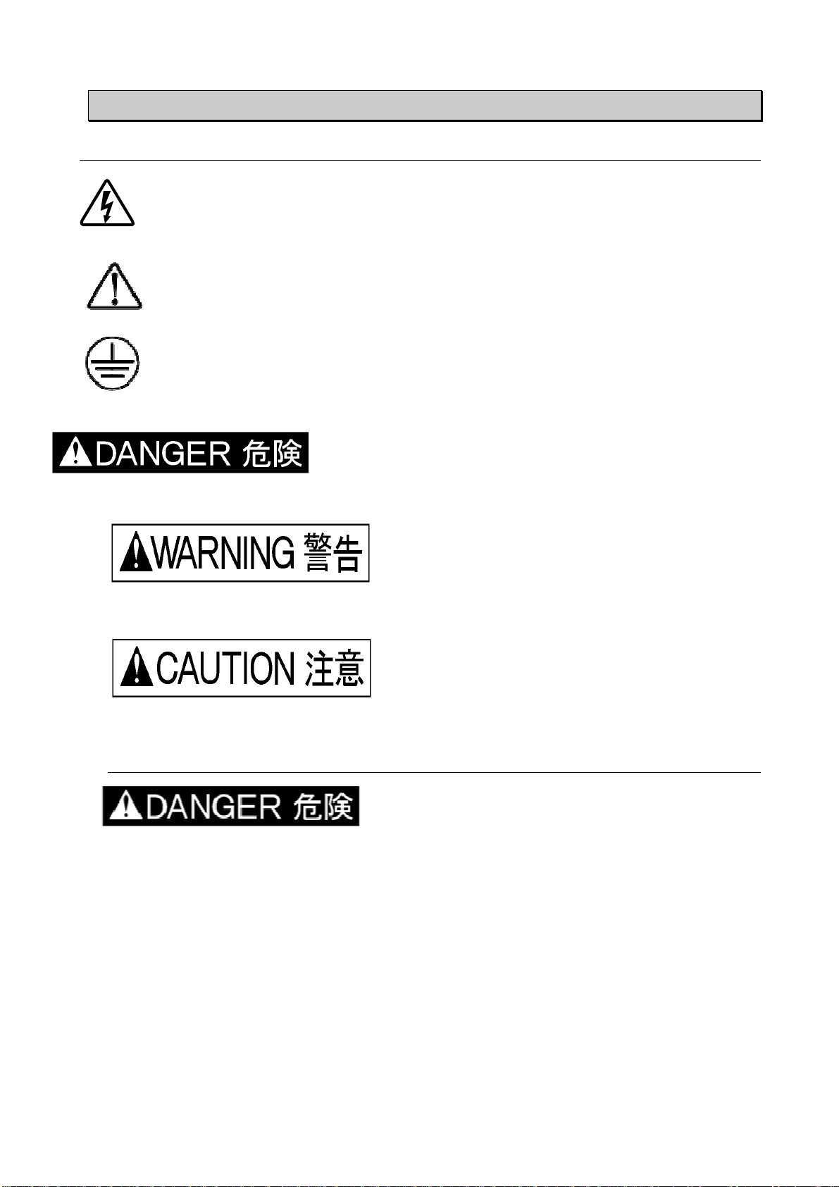
5.1 Warning signs and their meanings
This sign is shown at areas where HV voltages potentially hazardous to human
are present.
Sign for caution. For potential dangers or mishandling that could cause injuries
or material damage, this instruction manual shall be referred to.
Sign for a protective earth terminal.
Means
a danger.
If such a danger is not avoided, it leads to a state of
critical urgency, which
should result in a death or serious injury.
Means
a warning.
If such a danger is not avoided, a potential danger
which may result in a death or serious injury will
be caused.
Means
a caution.
If such a danger is not avoided, a potential
danger which may result in a minor or medium
degree of injury will be caused.
5.2 Basic safety precautions
1. Any person who has an implanted pacemaker in the body should not
operate this unit. Furthermore, such a person should not enter the test area
while this unit is operating.
【
【【
【Precautions for human body and operation】
】】
】
2. Use of this unit in an explosive area such as "No fire" area etc. is
prohibited. If used in such an area, it is liable to cause combustion or
ignition due to discharge.
【
【【
【Precautions for human body and environments】
】】
】
3. The AC INPUT (AC inlet) terminal on the rear panel has a conductor for
safety grounding connection. This unit shall be connected to a properly
grounded service outlet through the AC INPUT. When this unit is not
grounded through the AC INPUT, PE terminal positioned next to it shall be
used.

9
【
【【
【Precautions for connection】
】】
】
4. Before connecting the EUT LINE INPUT to a power supply, be sure to turn
off the power supply, otherwise supply power voltage may cause an electric
shock hazard.
【
【【
【Precautions for human body and connections】
】】
】
5. High voltages exist inside the unit. Never open the covers, except when a
mercury relay replacement is required. 【
【【
【Precautions for human body】
】】
】
6. Mishandling and careless operation of this unit will result in a deadly injury.
【
【【
【Precautions for human body, operation, environment and connection】
】】
】
1. The test rig used in conjunction with this unit should be insulated against a
minimum voltage of 8kV (when the built-in 50Ωterminator disconnected from
the test circuit).
【
【【
【Precautions for environments】
】】
】
2. Be sure to connect the ground plane to the safety ground.
【
【【
【Precautions for operation and safety】
】】
】
3. When connecting cables and carrying out settings, place the unit in the
STOP conditions and interrupt the EUT supply beforehand, otherwise, an
electric shock due to high voltage may be caused or the unit may be damaged.
Even in the STOP conditions, allow 5 seconds to elapse, as residual voltages
may exist.
【
【【
【Precautions for human body and connection】
】】
】
4. The coaxial connectors used for this unit is of NoiseKen original design. Use
of other type of connectors may cause electric shock hazards or malfunctions
of the unit.
【
【【
【Precautions for handling and safety】
】】
】
5. Fully put in each coaxial connector and make sure connections by rotating it clockwise
until a “click” is heard. Insufficient connection leads to unwanted discharges inside the
coaxial connectors. 【
【【
【Precautions for human body and connection】
】】
】
6.
Any other connection than the supplied SG short plug shall not be
connected to the SG connector of this unit. Wrong connections may apply HV
pulses to the ground plane, causing a shock hazard.
【
【【
【Precautions for human body and connection】
】】
】
7. To ensure safety in operation, use the accessories (use power cord and LINE
input cable with relevant safety agency approval) and optional equipment
supplied by our company. Use of others may degrade the safety and
performance of this unit.
【
【【
【Precaution for handling and safety】
】】
】
8. This unit has no built-in protection circuit for EUT supply. An external protective device
such as fuses, circuit breaker or protector meeting the EUT rating shall be installed.
9. When conducting coupling tests to the EUT LINE, the signal ground of the HV
pulse generator circuit and one line of the EUT LINE may be connected, causing a
shock hazard if the users touch the outer conductor of the HV coaxial connectors.
In addition, if the outer conductor of the HV coaxial connectors is connected to
any grounded object, leak current will flow, tripping the ground fault interrupter

10
embedded in the facilities. To avoid these two types of events, use of an isolation
transformer is indispensable. Be sure to connect the EUT LINE INPUT to the
isolation transformer secondary. 【
【【
【Precautions for human body and connection】
】】
】
10. When connecting cables and carrying out settings, place the unit in the STOP
conditions and interrupt the EUT supply beforehand, otherwise, an electric shock
due to high voltage may be caused or the unit may be damaged. Even in the STOP
conditions, allow 5 seconds to elapse, as residual voltages may exist.
【
【【
【Precautions for human body and connection】
】】
】
11. While this unit is producing pulses or EUT power is being supplied to the EUT
LINE INPUT, do not touch the HV coaxial connectors. Touching them may cause a
shock hazard.
【
【【
【Precautions for human body and operation】
】】
】
12. NOISE LABORATORY and its sales agents shall have no liability against any
accident resulting in injury or death, any damage to equipment or any resultant
damage thereof, which is caused by abuse or careless handling of this unit.
【
【【
【Precautions for human body, operation, environments and connection】
】】
】
1. As this unit employs a mercury relay, it shall be positioned horizontally only.
【
【【
【Precautions for handling】
】】
】
2. Do not supply voltage exceeding the rated voltage range. Do not connect the
EUT exceeding the rated power capacity of this unit.
【
【【
【Precautions for installation and connection】
】】
】
3. The SG terminal provided on the front panel of this unit functions as the
signal reference ground for testing. The PE terminal (EUT) is for the protective
earth conductor for the EUT. The protective earth terminals for this unit itself are
the AC inlet earth pin (AC INPUT) and PE positioned in close proximity to it. These
SG, EUT PE, the simulator PE are independent each other. When conducting tests,
make connections according to Section 10 test Set-ups.
【
【【
【Precautions for operation and connection】
】】
】
4. The supplied SG short plug shall not be connected to any other port than
L1, L2, PE injection connector or SG coaxial connectors. Connection to the
wrong port may damage the unit.
【
【【
【Precautions for operation and connection】
】】
】
5. The PE terminals of EUT LINE INPUT and EUT LINE OUTPUT are floating from the
chassis of this unit similarly to L1 and L2 terminals. When using the PE line, use an
appropriate power cord meeting your country’s safety regulations and EUT power rating.
6. During test, high level of electromagnetic radiation may be generated
depending on the type or nature of the EUT and thus causing interference with
nearby electronic equipment and radio communication equipment. In such case,
the user may have to take measures such as a faraday cage, shielded room,
and shielded cable and so on. 【
【【
【Precaution for environments】
】】
】
7. Do not use nor keep the unit in a hot or cold environment (Operating
temperature: 15°C~35°C/Operating humidity range: 25~75%) otherwise, the unit
may be damaged or only exhibit limited performance. 【
【【
【Precaution for

11
environments】
】】
】
8. If condensation is found, fully dry the unit before operating it, otherwise,
the unit may be damaged or only exhibit limited performance. 【
【【
【Precautions for
environments】
】】
】
9. The coaxial connectors used for this unit may have a shortened life due to a
poor insulation capability caused by a metal powder accumulation on the
connecting part, generated by a frictional wear with insertion and removal.
Clean the connectors by blowing a high pressure air. 【
【【
【Precautions for
handling】
】】
】
10. When installing the unit, do not block the vent. 【
【【
【Precaution for
environments】
】】
】
11. Do not drop the unit or do not give strong shock to the unit.
【
【【
【Precaution for handling】
】】
】
12. Do not wipe off the body and peripheral equipment with thinner, alcohol or
other solvent. When the unit is dirty, soak a cloth in a detergent, wring it and
wipe the unit with this cloth. Using solvents may spoil the appearance.
【
【【
【Precautions for handling】
】】
】
13. Only a service engineer authorized by our company should perform repair,
maintenance work and internal adjustment.
【
【【
【Precaution for handling and safety】
】】
】
14.
This unit employs a user-replaceable mercury switch. The component shall
be disposed of in conformity to the local regulations. Similarly, when scrapping
the product, follow the regulations.
5.3 When warning label is missing
1. When warning label is lost, or peeled off or dirty, put up a new one for extra safety.
2. When warning label is lost, contact our company's sales dept. or maintenance dept. for
issuance.
5.4 Restrictions to comply with CE marking requirements
1. Restrictions to comply with Low Voltage Directive (EN61010-1).
Use an AC cord and LINE Input cord with European Safety Agency approvals.
2. Installation category (for details, refer to IEC 664)
Installation category II: local level, appliances, portable equipment etc., with smaller
transient over voltages than installation category III.
3. Pollution degree
Pollution degree 2: Normally only non-conductive pollution occurs. Occasionally,
however, a temporary conductivity caused by condensation must be expected.

12
5.5 Coaxial connectors used for this product
The coaxial connectors used for this unit is of NoiseKen original design. Use of
other type of connectors may cause electric shock hazards or malfunctions of
the unit. Be sure to use accessories and options supplied by our company.
We have updated coaxial connector specifications to match the output pulse voltage
from the NoiseKen INS. This product (INS-4020/4040) uses a custom design
connector called NMHV which our company designed for 3kV or higher voltage
application. In the market, there are some other types of coaxial connectors similar to
the NMHV. Even when they have similar appearances, they are different from the
NMVH in terms of the inner conductor projection and length of the insulator.
Misconnection of a different type of connector to the NMHV may cause internal
discharges, leading to an unexpected shock hazard or a failure of this product. For
avoiding this kind of misuse, a marking of “NMHV-P-55U” is given on the fringe of the
leading edge of a connector lock. If NMHV connectors have been mixed up with other
types of connectors, discriminate NMHV connectors and use them only. Before
adoption of the NMHV, our company used the other type connector called MHV for
INS-400 series (2kV pulse output) such as model INS-410, INS-420 etc. and their
options. The MHV connector cannot be used for this product (INS-4020/4040) for the
above mentioned reason. The NMHV and MHV connectors are quite different in
appearance and thus they can be easily identified.
When using an external coupling unit such as IJ-4050 or other optional products,
check the connector type and use accessory and cables supplied by our company.
MHV:INS-400 seris
N M H V
-
P
-
5 5 U
NMHV:INS-4020/4040

13
6 GENERAL DESCRIPTION
This unit generates fast rise time square wave pulses and couples them to the power
supply lines of the EUT for noise testing purpose.
6.1 Features
• Generates pulses of less than 1ns rise time up to 4kV (INS-4040) or up to 2kV (INS-4020).
• Selectable pulse widths from 50ns to 1000ns at a step of 50ns, 10ns available as the shortest
width.
• Easily selectable coupling modes to EUT power lines.
• Maximum EUT voltage and current rating: 240V AC, 16A.
• Generates pulses in synchronization with EUT power line frequency. Placement phase angle can
be controlled from 0 to 360 degrees.
• Capability for a single pulse by using the manual trigger and for synchronization with external
signals.
• Automatic ramp capability provided for the output voltage, placement phase angle and pulse
repetition period.
• 3 phases coupling unit (415V/50A) is optionally available and operation in synchronization with
the relevant supply is also available.
• Triangular wave pulse unit is optionally available.
• Built-in terminator.
• Optional outlet panels are available for an easy connection of the EUT to this unit and for
better reproducibility in testing. Various receptacle types are available.
• Optionally provided are radiation probes, coupling clamps and others.

14
6.2 Pulse generation principle
The main components of the pulse generator circuitry of this unit are coaxial cables,
HV power supply, charging resistor, mercury relay and terminating resistor. The
coaxial cables form a distributed constant circuit consisting of the inductance of the
inner conductor and capacitance of the inner conductor to outer conductor. When a
50Ωresistance terminates this line, it works as a square wave pulse generator.
Pulse widths vary depending on the delay time of the coaxial line (length of the
cable). The proportion of pulse widths to the length is approximately 10 ns per meter.
Pulse waveforms and voltages depend on the relation between terminator resistance
and coaxial cable characteristic impedance. The HV power supply charges up the
capacitance component of the coaxial line through the charging resistor when the
mercury relay is in off status. The stored energy is discharged when the mercury
relay contacts turn on, generating a HV square wave pulse across the terminating
resistor. The injection unit couples this pulse through a capacitor to a EUT LINE.
Also provided is a Decoupling circuit consisting of an inductor and capacitor, working
as a high impedance circuit when seen from the injection point. This enables to
effectively couple the interference signals to the EUT and to reduce them to leak into
the power supply side (LINE IN).
CC
R2
HV
S1
EUT L1
EUT L2
EUT PE
SG
EUT L2
EUT L1
EUT PE
L1
L2
L3
C1
C2
C3
R1
LINE IN
LINE OUT
DC OUT
PULSE IN
PULSE OUT
50ΩTERM IN
50ΩTERM OUT
C4
C5
C6
HV:
HV power supply R1:
Charging resistor CC: Coaxial cable
S1: Mercury relay R2:
Termination resistor C4,5,6: Coupling capacitor
L1/C1,L2/C2,L3/C3: Filter

15
6.3 For perfect matching
Pulse waveforms and amplitudes are dependent on the value of a termination resistor being
connected to the PULSE OUT terminal. The figures and equation shown below describe these
relations. To generate square wave pulses, this unit adopts a 50Ω(strictly, 53.5Ω), equal value to
the characteristic impedance of the coaxial cables.
E E E
t t
R2=Zo
R2=ZoR2=Zo
R2=Zo R2=3Zo
R2=3ZoR2=3Zo
R2=3Zo R2=1/3Zo
R2=1/3ZoR2=1/3Zo
R2=1/3Zo
1/2E
3/4E
3/8E
3/16E 1/4E
1/8E
1/16E
t
Vp=R
2
÷( Z
0
+R
2
) ×E・・・・・・・・・・・ (equation 1)
E
: Output voltage from the HV power supply
Vp
: voltage being measured across the terminating resistor
Z0
: characteristics impedance of the cable cables
R2
: value of terminating resistor

16
6.4 Range of settings for pulse and other parameters
This unit can be set in the range in the table shown below.
Table 1 Range of settings
Parameters Specifications
Output voltage 0.01kV~2kV (INS-4020) at 0.01kV step
0.01kV~4kV (INS-4040) at 0.01kV step
Pulse polarity Positive/Negative
Pulse width 50ns~1µs (50ns step) and 10ns
Trigger mode PHASE (EUT line synchronization)
VARIABLE (asynchronization)
Placement phase angle in
PHASE mode 0~359° at 0° step
Pulse repetition in
VARIABLE mode 10~999ms(INS-4020) at 1ms step
16~999ms (INS-4040) at 1ms step
(Note 1) The output voltage display reads the correct pulse voltage only when the
built-in terminating resistor terminates the coaxial line (at the PULSE OUT)
When the terminating resistor is disconnected from the test circuit, the
actual pulse amplitude is approximately 1.8 times of output voltage display
reading and its waveform no longer square (damped). An automatic
correction for the voltage indicator is available by means of turning on the
unit with a different key operation. For details, refer to Section 9.10.
(Note 2) The fastest repetition of generated pulses (VARIABLE) is 10ms for INS-4020
and 16ms for INS-4040. This comes from different construction of the two
types of mercury relay.
17
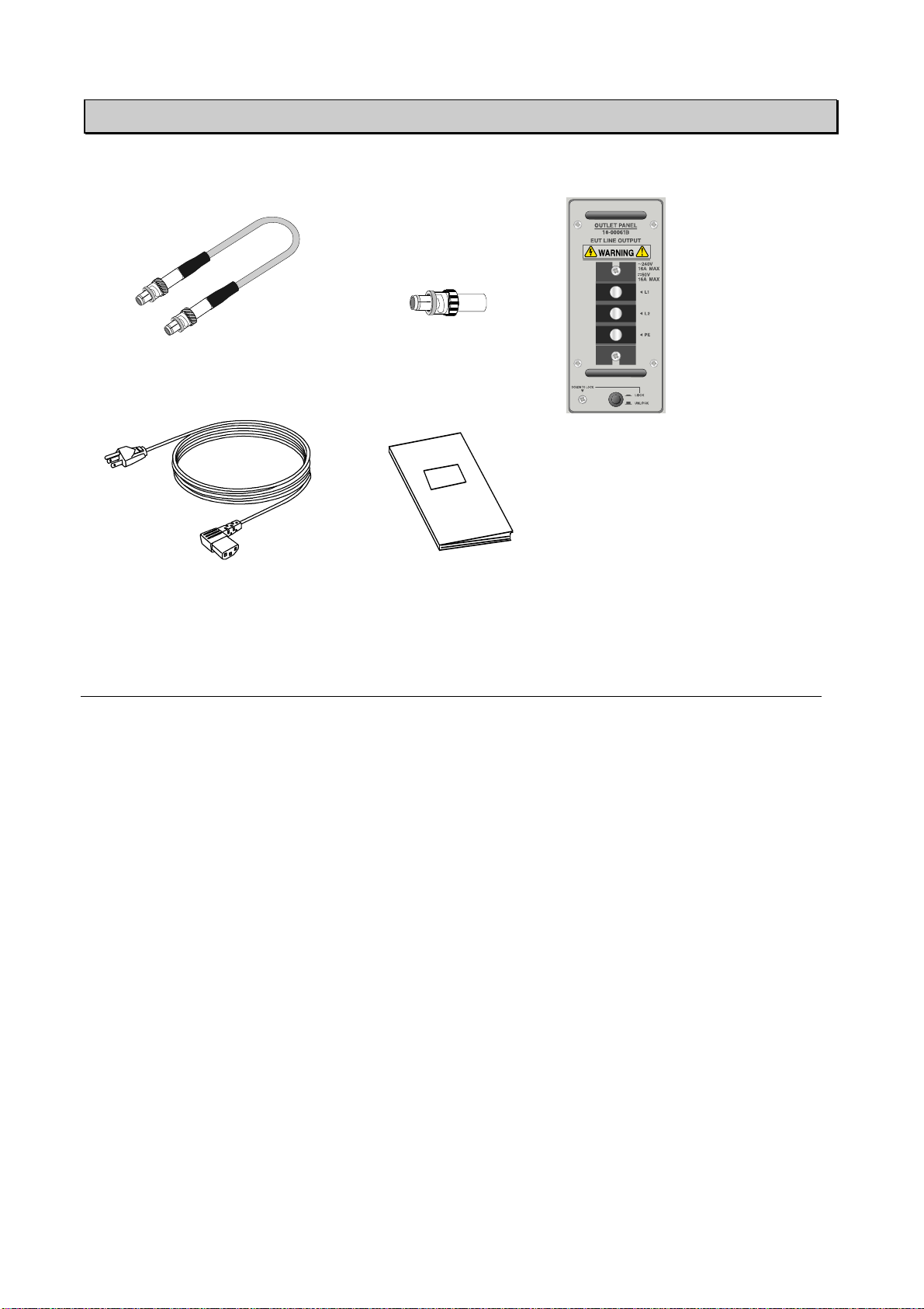
7 INCLUDEDACCESSORIES
This product includes the following accessories.
A B C
D E
List of the included accessories
Description Quantity
Note
A
Coaxial cable 02-00013A 8 30cm length
B
SG short plug 02-000106A
1
C
Outlet panel
(Terminal block
type)
18-00061B 1 AC240V/16A
DC60V/16A maximum
Leaves the factory with this panel
attached to the main unit.
D
AC cable 1 AC100-115V 3-p, 2.4m
E
Instruction manual 1
18
8 CONTROLSAND DISPLAY FUNCTIONS
On the front of the simulator, control, setting and output sections are provided. On the rear, mains
input terminals for the simulator and mains input terminals for EUT are provided.
8.1
8.1 8.1
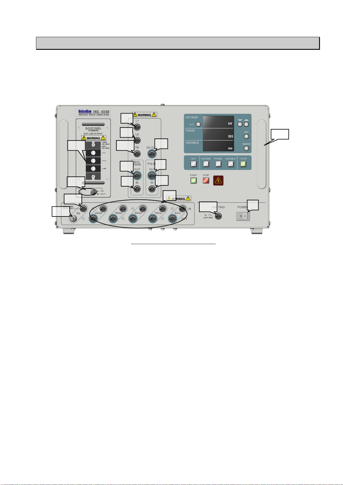
8.1 Front panel connecters and terminals
INS-4020/4040 front panel
1. POWER key
Controls main POWER on and off. The | side is on position and the 0 side is off position.
2. DC OUT
HV DC OUTPUT connector. This terminal shall be connected to PULSE WIDTH terminal by
using a supplied coaxial cable.
3. PULSE WIDTH
Selects a pulse width among 50ns, 100ns, 200ns, 250ns, 400ns and any
combination thereof. Pulse width can be set from 50ns to 1000ns at a 50ns step by
using supplied coaxial cables. For more details, refer to Chapter 8 Operation.
4. PULSE OUT
PULSE OUTPUT connector. Outputs the pulses set through PULSE WIDTH section.
5. PULSE IN
PULSE INPUT connector. The DC output set through PULSE WIDTH section is input to this
terminal through a supplied coaxial cable.
6. 50ΩTERM OUT
Output at 50Ωtermination resistance. The pulse output with the selected peak amplitude exists
across this terminal.
7. 50ΩTERM IN
Input connector for 50Ωtermination resistor. The HV output pulses from PULSE OUT terminal
are input to this terminal through a supplied coaxial cable.
8. L1
1
2
3
4
5
6
7
8
10
9
11
12
13
14
15
16
This manual suits for next models
1
Table of contents


