Dreadbox telepathy User manual


installation
34
34
Always turn off your
Eurorack system before
installing the Telepathy
module. Telepathy has a
Power consumption of
107mA of +12V and
24mA of -12V. The
module’s ribbon power
cable is attached to the
module via a header for
extra protection when
mounting. The red line
should always be on the
bottom side of the module
as shown on the photo to
prevent any damage.
warranty
Dreadbox warrants this product to be free of
defects in materials or construction for one year
from the date of purchase.
Proof of purchase is necessary when the
warranty claim is made.
Malfunctions resulting from improper power
supply voltages, backward or faulty cable
connection, abuse of the product or any other
causes determined by Dreadbox to be the fault
of the user, are not covered by this warranty
(normal service rates will be applied).
All defective products will be replaced or
repaired at the discretion of Dreadbox.
Products must be returned directly to Dreadbox
with the customer paying the shipping costs.
Dreadbox implies and accepts no responsibility
for harm to a person or apparatus through the
operation of this product.
Please contact support@dreadbox-fx.com for
the return to manufacturer authorization, or for
any other technical questions or concerns.

PLEASE NOTE: The red stripe should
always be on the bottom side of the module
A 10 Pin to 16 Pin Ribbon cable
56
The Telepathy module
A 3,5 mm to DIN5 MIDI adapter
(type A).
This cable is used to transfer MIDI
data to the Telepathy module from
an external MIDI device. You can
also transfer data with a 3,5 mm
stereo jack if the MIDI device allows
it and supports it.
The jack converter is an Atype.
A 3,5 mm stereo jack.
This cable is used to chain multiple
Telepathy modules together. To
achieve this, send the MIDI OUT to
the MIDI IN of the next Telepathy.
IN the box you will nd:
4 x M3 X 6 screws.

78
78

Telepathy is a Full Voice Analog Synthesizer
module with deep modulation options due
to its multi-destination LFO and Envelope.
From bass to lead sounds, to drums and
drones, Telepathy has broad and versatile
sound design capabilities.
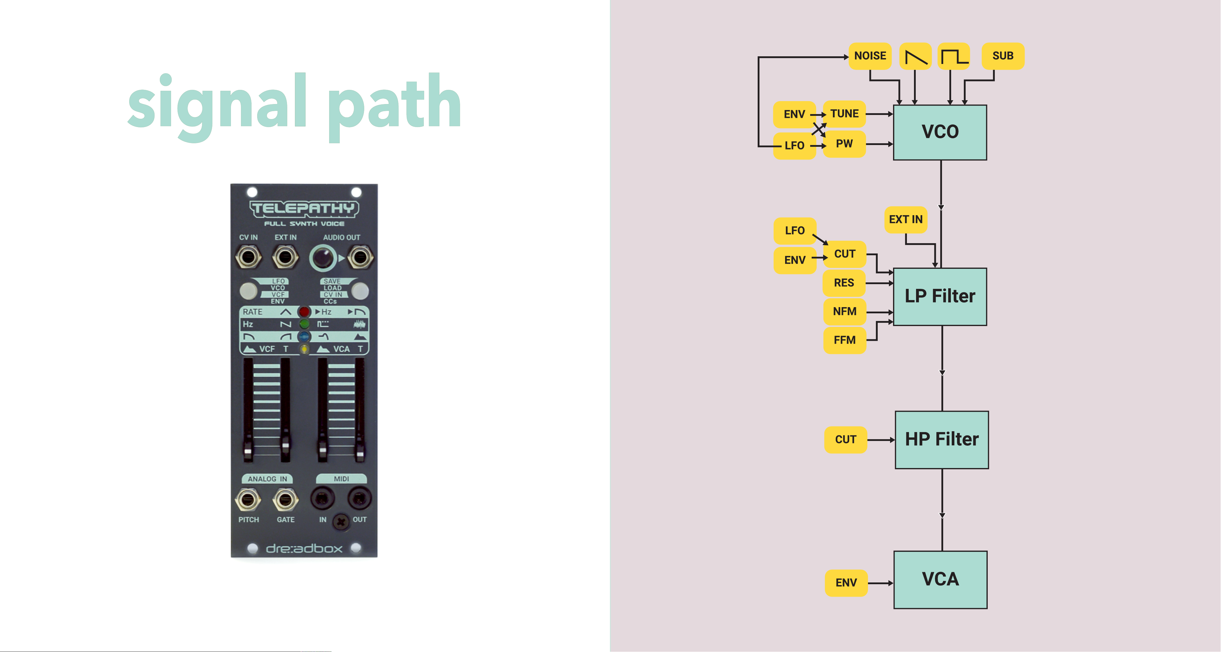
It has a full analog path (Classic Dreadbox
VCO, 4-pole low pass lter/2-pole high
pass lter, VCA) that is digitally controlled
for more precision over its parameters.
This results in the familiar warm, present
and distinct Dreadbox sound.
Telepathy has an intuitive parameter
navigation matrix, with multicoloured
LED indication.
It is also capable of saving and recalling
up to 16 presets and there is a Full MIDI
implementation for CCs and Program
Changes for all the parameters.
The possibilities expand even more, when
connecting two or more Telepathy modules
together. This results in a Polyphonic
Multitimbral synthesizer that opens up a
new sonic world.
With lots of useful and musical features
integrated into a compact size (10hp), and
also its skiff friendly design, Telepathy is a
great addition to a smaller or a larger
eurorack system.
overview
910
telepathy

panel controls
11 12
Telepathy consists of two main sections to navigate its menu.
Telepathy uses a simple yet very effective control matrix to navigate
through its multiple parameters and affect the sound. It always
follows a top down approach.
SECTIONS
The two buttons on the panel indicate and control the two main
sections of the module.
These are the Voice Section on the left and the Menu Section on the
right. Each section has its own functions called Pages. Pressing the
left or the right button enters the corresponding Pages.
PAGES
Each Section consists of 4 Pages. On the Voice Section you will nd
the LFO, VCO, VCF, ENV and on the Menu Section the SAVE, LOAD, CV
IN, CCs.
MATRIX
Each of the four Pages corresponds to one of the four rows of the
matrix on the panel. Each Page is assigned to a different LED color for
easier distinction (Red,Green,Blue,White).

13 14
CV IN: Accepts any external CV signal rated at ±5 Volts. Through
the CV IN Menu Page, you can assign all the main parameters by
setting each independent modulation amount.
EXT IN: Accepts any audio signal. This signal gets mixed with the
Oscillator at the input of the LP Filter. In this way the LP Filter,HP Filter
VCA and their modulations can be used to alter the behavior of the
external audio.
AUDIO OUT: Mono Audio OUT with level control.
PITCH: 1V/oct analog input that affects the pitch of the internal Oscillator.
GATE: It accepts Gate signals.
MIDI IN: TRS MIDI Type A input.
MIDI OUT: TRS MIDI Type A output that acts both as Through and Output.
Pressing the button that corresponds to one of the sections you can
cycle through the different Pages (Matrix rows).
When a Page is chosen, the sliders are used to affect the different
parameters according to their current position (Matrix columns).
SHIFT FUNCTION
To control additional functions of the Pages hold down the Voice
Button. These are called shifted functions that affect additional
sonic parameters.

Slider 1 Slider 2 Slider 3 Slider 4
LFO LFO Rate LFO Wave LFO Pitch Amount LFO Cutoff Amount
Shifted Fade IN Free/Key/Track/BPM/
BPM Key LFO PW Amount LFO Noise Amount
VCO Tune Waveshape PW Noise Level
Shifted ±12 Semi
Quantized/Full Range
Unquantized LFO Wave Amount EG PW Amount VCO Level
VCF Cutoff HPF Resonance EG Cutoff Amount
Shifted Tracking FFM Amount NFM Amount EG Pitch Amount
ENV VCF EG Shape VCF EG Time VCA EG Shape VCA EG Time
Shifted VCF Sustain VCF EG Loop VCA Sustain Drone State
PAGE 1 - LFO (RED LED)
LFO RATE: It controls the rate of the Low Frequency Oscillator. It
ranges from 40 seconds when the slider is all the way down, to 110Hz
for subtle audio rate modulation.
LFO WAVE: Depending on the position of the slider, the LFO can
have the following shapes: Triangle SAW Ramp Square
Stepped Random. (
Schema 1
)
Schema 1
15 16
By pressing the Voice Button we enter the Voice Pages and adjust the
parameters of the matrix with the four sliders.
The Voice Section consists of four Pages. The LFO, VCO, VCF, ENV.
Each Page corresponds to a line on the matrix and is indicated by a
specic LED colour.
Pressing the Voice Button cycles between the four Pages.
VOICE PAGES
SHIFT= press and hold down the Voice button
Slider1
Slider2

Slider3
Slider1
Slider4
Slider2
Slider1
Slider2
Slider3
Slider4
LFO PITCH AMT: It adjusts the LFO modulation amount of the VCO pitch.
LFO CUTOFF AMT: It adjusts the LFO modulation amount of the LP
Filter Cutoff Frequency.
LFO SHIFT PAGE: (Can be accessed by holding the Voice Page Button
while adjusting the sliders values).
LFO FADE IN: This refers to the time it takes for the LFO to start
modulating, after the played note. Ranges from 1ms to 5 sec.
(Schema 2)
LFO MODES
Free: Running freely without being affected by the played note.
Key sync: The LFO waveform always resets to its beginning when a
new note is played.
Key track: LFO cycle speeds up according to the Pitch of the
played note.
Schema 3
17 18
17 18
BPM sync: The LFO rate tracks the MIDI clock, independent of the played
note. The LFO rate works in divisions of 1, 2, 3, 4, 6, 8, 12, 16, 24, 32.
BPM key sync: The LFO rate tracks the MIDI clock and its waveform is
reset to its beginning whenever a new note is played.
LFO PW AMT: It adjusts the LFO modulation amount of the VCO
square wave pulsewidth.
LFO Noise Amount: Adjusts the LFO modulation amount of the Noise level.
PAGE 2 - VCO (GREEN LED)
Tune: It adjusts the pitch of the oscillator. Default range -12st to +12st.
Can be further adjusted with the shift function.
Waveshape: It adjusts the shape of the oscillator wave.
(Schema 3)
From Sawtooth Sawtooth+Sub blend
Sub OSC (square) Square/Sub blend Square
sub
Schema 2

VCF SHIFT PAGE: (Can be accessed by holding the Voice Page Button
while adjusting the sliders value).
Tracking: It adjusts the key tracking amount of the LP Filter Cutoff.
Higher notes will result in higher frequencies on the LP Filter Cutoff.
FFM: It adjusts the amount of VCO triangle wave (FM) modulating the
LP Filter Cutoff.
NFM: It adjusts the amount of Noise (FM) modulating the LP Filter
Cutoff.
EG PITCH AMOUNT: It adjusts the EG modulation amount on the
pitch of the VCO.
PW: It changes the PW of the square wave.
Noise Level: It adjusts the volume of the noise source.
VCO SHIFT PAGE: (It can be accessed by holding the Voice Page Button
while adjusting the sliders value).
TUNINGS:
• ±12st Quantized
• Full range Unquantized values (8 octaves)
LFO WAVE Amount: It adjusts the LFO modulation amount of the VCO wave.
EG PW Amount: It adjusts the EG modulation amount of the VCO pulse width.
VCO LEVEL: It adjusts the volume of the Oscillator. The default VCO level
is at the middle of the slider. When increasing the slider value it boosts
the signal and drives the lter.
PAGE 3 - VCF (BLUE LED)
Cutoff: It sets the Cutoff Frequency of the low pass lter.
HPF: It sets the Cutoff Frequency of the high-pass lter.
Resonance: It sets the amount of resonance. In max settings the lter
will self oscillate.
EG Cutoff Amount: It adjusts the EG modulation amount of the LP
Filter Cutoff.
19 20
Slider1
Slider1
Slider2
Slider2
Slider3
Slider3
Slider4
Slider4
Slider3
Slider4

21 22
PAGE 4 ENVELOPE (WHITE LED)
The Envelope follows the classic ADSR sound shaping approach over
time, but with a twist on the way it gets controlled via a SHAPE, TIME
and SUSTAIN control.
(Schema 4)
SHAPE: The shape parameter denes the relationship between the
attack and decay/release times. It can range from a Sawtooth shape
(no attack, only decay) to a triangle shape in the middle of the slider
(equal attack and decay), to an inverted sawtooth (only attack, no
decay). Of course the Envelope can be further shaped using all the in
between positions of the slider.
TIME: Time denes the overall duration of the Envelope. It sets the
duration of both attack and decay/release times. Increasing its value
results in equal amounts of change to the attack and decay/release.
Envelope times: 3 ms to 20 sec for a full Envelope cycle.
Schema 4
SHAPE
Slider1
Slider2
Slider3
Slider4
VCF EG SHAPE: It adjusts the Shape of the VCF Envelope.
VCF EG TIME: It adjusts the Time of the VCF Envelope.
VCA EG SHAPE: It adjusts the Shape of the Envelope applied to the VCA.
VCA EG TIME: It adjusts the Time of the Envelope applied to the VCA.
ENVELOPE SHIFT PAGE: (Can be accessed by holding the Voice Page
Button while adjusting the sliders values).
VCF SUSTAIN: It adjusts the sustain level of the VCF Envelope.
VCF EG LOOP: It activates or deactivates the looping of the VCF Envelope.
VCA SUSTAIN: It adjusts the sustain level of the Envelope applied
to the VCA.
DRONE STATE: It activates or deactivates the drone mode. Sets the
VCA to open constantly.

23 24
EXAMPLE
VOICE SECTION
Press the Voice Button once, to enter the Pages of the Voice Section
(LFO, VCO, VCF, ENV).
The red LED light on the rst matrix row is on, to indicate that we are
now in the rst Page, in this case the LFO Page. Move the 1st slider to
affect the rate of the LFO.
Press the Voice Button once again to start navigate through the matrix
rows. Now the LED light has turned green to indicate that we are in the
2nd matrix row and therefore in the second Page, meaning the VCO
Page. Move the 4th slider to alter the noise level. Additionally move the
1st slider to adjust the VCO pitch.
Pressing once again you will be moved to the next row and the sliders
will now affect the parameters corresponding to the specic Page.
To RETURN to the LFO Page (1st row), press the Voices Button to
cycle through the matrix rows. Note that the LED light color helps to
indicate the matrix row. In this case we expect to see it turning red
again.
Lastly, let’s alter a parameter that is in the shifted menu. While on the
LFO Page press and hold the Voices Button and move the 1st slider to
affect the Fade IN time of the LFO.

25 26
Slider 1 Slider 2 Slider 3 Slider 4
SAVE Bank Preset
Long Press Menu Button to Save the selected Preset.
LOAD Bank Preset Initial Preset
Long Press Menu Button to Load the selected Preset or Initial Preset.
CV IN CV Amount CV Amount CV Amount CV Amount
Voice Button cycles between the main controls of the Voice Pages.
Long Press Menu Button to clear all CV Amounts.
CC CC IN CC OUT PC IN PC OUT
Press and Hold the Menu Button to engage MIDI Learn.
When the Button is released the last played channel will get selected and saved.
By pressing the Menu Button we enter the MENU PAGES. The
procedure of navigating the parameter is identical to the VOICE
SECTION. We enter the MENU PAGES by pressing the Menu Button
and adjust the parameters of the matrix with the four sliders.
The MENU SECTION consists of four Pages:
The SAVE, LOAD, CV IN, CCs. Each Page corresponds to a line on the
matrix and is indicated by a specic LED color.
Pressing the Menu Button cycles between the four Pages.
MENU PAGES
PAGE 1 - SAVE (RED LED)
Press the Menu Button once to enter the Save Page. The LED light on
the 1st matrix row is red to indicate the current Page (Save). In this
Page the Menu Button blinks fast.
menu section

Schema 5
The Banks and Preset Slots start at the bottom with both sliders in the
minimum position and progressively go to increase Banks and Preset
Slots by adjusting the position of the sliders. At the maximum slider Bank
and Preset Slot position, Bank 4 / Preset Slot 4, preset will be selected.
A slow ashing of the LED indicates the Bank number.
27 28
A fast ashing of the LED indicates the Preset Slot number.
When the Bank and Preset Slot position coincide (1,1), (2,2), (3,3), (4,4)
then the LED light ashes even faster.
EXAMPLE
We created a sound we want to save.
Press the Menu Button once, the red light is on, to indicate that we are
now on the Save Page at the 1st matrix row and also the Menu Button
will ash fast.
At the same time you will notice one or more colored LEDs are ashing
to indicate the Bank and Preset Slot. Position (Bank 1, Preset Slot 1) is
indicated when both the slow and the fast LEDs are ashing and are
visible together in the 4th matrix row and the sliders are positioned all
the way down. (
Schema 5
)
Save a preset in Bank 2, Preset Slot 3 (
Schema 6
)
• Move the slider 1 to the desired position. In this case the second
position. (BLUE LED blinks slowly).
• Move the slider 2 to the desired position. In this case the 3rd
position. (GREEN LED blinks fast).
• Press and hold the Menu Button for one second to save the
preset. The Menu Button will ash in a sequence to conrm the
preset got saved.
PRESS THE VOICE BUTTON TO RETURN TO THE VOICE PAGES.
Constant RED
to indicate SAVE PAGE
Fast ashing (WHITE)
PRESET SLOT
11
22
33
44
BANK

29 30
PAGE 2 - LOAD (GREEN LED)
Press the Menu Button to enter the LOAD Page indicated by the
GREEN LED .
The same principle as the SAVE process applies when you want to
load a preset.
Schema 6
EXAMPLE (
Schema 7
)
Loading a preset located in Bank 1, Preset Slot 4 (1,4)
Press the Menu Button to enter the LOAD Page indicated by the green
LED in row 2 of the matrix and also by a slow ashing on the Menu
Button.
Move the slider 1 all the way down to select Bank 1 (slow blinking
white LED).
Move the slider 2 all the way up to select Preset Slot 4 (fast blinking
red LED)
Press the Menu Button for one second to load the selected preset.
The Menu Button will ash in a sequence to conrm the preset got loaded.
Constant RED
to indicate SAVE PAGE
Fast blinking GREEN (PRESET SLOT)
Slow blinking BLUE (BANK)
2
BANK PRESET SLOT
3
Constant GREEN
to indicate LOAD PAGE
Fast blinking RED (PRESET SLOT)
Slow blinking WHITE (BANK)
1
BANK PRESET SLOT
4
Schema 7

31 32
INITIAL PRESET
There is an initial preset that resets values and can be chosen through
the slider 4 in the load Page.
• Move the slider 4 to select the initial preset. All 4 colored LEDs will
light up to indicate that the initial preset has been chosen.
(You can cancel the loading of the initial preset at anytime by moving
slider 1 or 2 to search for another preset.)
• Press the Menu Button for one second to load the initial preset.
PRESS THE VOICE BUTTON TO RETURN TO THE VOICE PAGES.
PAGE 3 - CV IN (BLUE LED)
Telepathy can accept CV signals, through its assignable CV IN input.
In this way, external CV sources can be assigned to modulate
Telepathy’s parameters.
In CV IN Page (constant blue light and lighted LEDs of both Buttons),
all the sliders are used to adjust the amount of CV applied to its
parameters. To navigate through the parameters, press the Voice
Button. A blinking LED will indicate the Voice Page you have currently
selected. Adjust the amount of CV for the desired parameter by
moving the sliders.
EXAMPLE
• Connect an external LFO to the CV IN.
• Let’s assign the external LFO to modulate the Filter Cutoff and the
waveshape of the VCO.
FILTER CUTOFF CV
Press the MENU Button and choose the CV IN Page indicated by the
constantly lighted blue LED (3rd matrix row) and the lighted LEDs of
both buttons.
• Navigate the Voice Section Pages by pressing the Voice Button and
select the VCF Page (3rd matrix row). The blue LED is now ashing
to indicate the position of the Voice Pages.
• Adjust the CV IN amount to modulate the LP Filter Cutoff via slider 1.
VCO WAVESHAPE CV
Navigate in the Voice Section to the VCO Page (2nd matrix row, green
LED ashing).
Adjust the CV IN amount to modulate the VCO Waveshape according
to your own preference with the slider 2.
Press the MENU Button for one second to clear all set CV IN amounts.

33 34
PAGE 4 CC (WHITE LED)
In this Page you can control if the module responds or sends MIDI CC
values. In the CC Page, move the 1st slider past the middle position so
that the module responds to MIDI CC data (CC IN). In order for the
Telepathy to send CC values to control other device parameters, use
the slider 2 to activate the CC OUT. The same applies to Program
changes. With the use of the 3rd slider, Telepathy responds to program
changes (PC IN) and with the use of the forth slider it sends program
changes (PC OUT).
MIDI CHANNEL SETUP
To change the MIDI channel simply hold the Menu Button for more
than one second to engage MIDI learn. While still holding the Menu
Button press a note from your MIDI controller or DAW, on any MIDI
channel and Telepathy will respond. When the button is released the
last played channel will be selected and saved.
1Pitch LFO Amount
3Cutoff EG Amount
4Filter Tracking
7VCO Level
9Cutoff LFO Amount
10 Noise Level
11 PW
12 PW LFO Amount
13 Pitch EG Amount
14 Tune
15 Quantized
16 LFO Rate
17 LFO Wave
18 LFO Fade In
19 LFO Mode
20 Wave LFO Amount
21 PW EG Amount
22 Noise LFO Amount
23 FFM Amount
24 NFM Amount
25 VCF EG Wave
26 VCF EG Time
27 VCA EG Wave
28 VCA EG Time
29 VCF EG Sustain
30 VCF EG Loop
CC LIST
31 VCA Sustain
32 Velocity Amount
33 Drone
34 LFO Rate CV Amount
35 LFO Wave CV Amount
36 Pitch LFO Amount CV Amount
37 Cutoff LFO Amount CV Amount
39 Tune CV Amount
40 VCO Wave CV Amount
41 PW CV Amount
42 Noise Level CV Amount
43 Cutoff CV Amount
44 HPF CV Amount
45 Resonance CV Amount
46 Cutoff EG Amount CV Amount
47 VCF EG Wave CV Amount
48 VCF EG Time CV Amount
49 VCA EG Wave CV Amount
50 VCA EG Time CV Amount
70 VCO Wave
71 Resonance
74 Cutoff
81 HPF
120 All Sound Off
123 All Notes Off
Program Change 1-16 (0-15)

tuning mode
35 36
35 36
TUNING PAGE
Press the Voice Button to enter the Voice Pages.
While on the Voice Pages press both buttons to enter Tuning Mode.
Tuning Page is indicated by a slow ashing on both buttons and a
faster ashing on the white LED.
Pressing the Voice Button (left) will exit the Tuning Mode.
FINE TUNE
While on Tuning Page move the 1st slider to adjust the ne tune of the
oscillator.
AUTOTUNE
While on Tuning Page press the Menu Button once to engage the
autotune of the module. All LEDs will start ashing.
This will calibrate the scale and tune. Once this process is over the
module will return back to the Voice Pages.
ANALOG TUNING (Advanced Tuning)
While on Tuning Page press and hold the Menu Button to engage the
Analog Tuning.
The analog tune will calibrate the analog tune and scale of the
oscillator, all the MIDI notes and also the CV IN offset.
• After entering the Analog Tuning Page both White and Blue LEDs will
start ashing to indicate that the module is in the “Waiting for 1 Volt”
state and the VCA will open so as the sound is on.
*Mind that the sound settings will be as the ones already set.
• Disconnect any patches connected to Pitch and CV IN inputs and
connect your 1Volt/oct device you want to track to the PITCH patch point.
• Set your 1Volt/oct device to send 1 Volt (one octave higher than the
last note your device will output when no change is heard on
Telepathy’s oscillator) and press Menu Button once. A ashing on all
4 LEDs will start and then stop.
• Now the White and Green leds will start ashing to indicate the
“Waiting for 4 Volt” state. Send 4 Volts from your keyboard (3
octaves higher than the 1 Volt note) and press the Menu Button
again. A ashing on all 4 LEDs will start and stop once more.
• Then Green,White,Blue, will start ashing to indicate the
disconnection of the patch from the PITCH input of the module.
• Disconnect and press the Menu Button once more. Now all LEDs will
start ashing in a random way to indicate the MIDI Tuning. When
autotune is over the sound will stop and it will exit the Tuning Page.
Note that if no voltage is applied to “Waiting for 1 Volt” state, it will skip
the external CV Tuning and proceed to the MIDI Tuning right away.

indicate the number of Voices linked (Linked modules). Linked
Voices 1-4 appear through the LEDs from bottom up. Linked Voices
from 5-8 appear the same way while LEDs are ashing.
6. Press the Voice Button to exit and save at any time.
7. Mind that, when entering the Chain Mode there is no Voice
assigned, so the 1st press of the Menu Button assigns the Master
Telepathy, second press assigns the 1st linked Voice and so on.
MAIN LINKING MODES
A. Hard master mode/ Polyphony
1. While in Chain Mode, long pressing the Menu Button will enable or
disable the Hard Master mode. This means that the MASTER
Telepathy (the unit you set the chain) will transmit all the CCs when
loading a preset, to set the sound on every chained unit according to
the MASTER one.
This mode is indicated by a conrmation ashing and then a pause on
both button LEDs. If the pause is indicated by lighted LEDs then the
mode is enabled, if the pause is indicated by dimmed LEDs then the
mode is disabled.
37 38
Telepathy has the ability to link to other Telepathy modules in-
order to achieve polyphony and multitimbrality. Depending on the
Internal settings that will be explored further below you can
achieve several combinations of behavior between the modules,
once you chain them.
CHAIN MODE
To enter Chain Mode follow the steps below:
1. Press the Menu Button once.
2. While on the Menu Pages press both Menu & Voice Buttons once
to enter the Chain Mode.
3. Chain Mode is indicated by an alternating ashing of the button LEDs.
4. To select the preferable amount of Voices (number of Telepathy
modules in the Chain), press as many times the Menu Button of the
rst module. While pressing the button the alternate ashing appears
to the module that is being linked. You can set up to 8 Voices in total.
5. On the Master Telepathy (First module) the four coloured LEDs
polyphony &
multitimbral
Table of contents
Other Dreadbox Recording Equipment manuals
Popular Recording Equipment manuals by other brands

Heritage Audio
Heritage Audio 73 JR II user manual

Alesis
Alesis AcoustiFX Programming chart

METRObility Optical Systems
METRObility Optical Systems RADIANCE Series Installation & user guide

Furuno
Furuno CU-300 Operator's manual

Behringer
Behringer MiniFBQ FBQ800 quick start guide

Linear Acoustic
Linear Acoustic MetaMAXLA-5180 Operation manual