Nokeval MTR970 User manual

MTR970
Radio data receiver
User manual
Firmware versions V1.0-3.1
10.08.05

DESCRIPTION
MTR970 is radio data receiver or Nokeval MTR series wireless transmitters. It receives and bu ers the data packets that MTR
transmitters have sent. It automatically recognizes the types o the transmitters, so di erent kinds o transmitters can be used
simultaneously. Transmitters can also have di erent transmission intervals.
MTR970 uses license ree 433.92 MHz requency band (ISM) so it can be reely used, or example, almost in whole Europe.
MTR970 is designed or desktop use but it can also be installed, or example, upside down to a ceiling or to a cable rack. The
receiver is connected to a computer using RS-485 or RS-232 bus and it requires PromoLog application that reads the
in ormation rom the device.
Nokeval SCL protocol is used or data transmission between the receiver and the computer. Multiple receivers can be connected
in parallel to an RS-485 bus to increase the coverage area. The receiver has three indicator LEDs and it requires 9..30 VDC.
2

SPECIFICATIONS
Radio receiver
Antenna
Connector: 50 Ω BNC emale contact
Standard antenna: helical whip antenna (BNC connector)
Polarization: Vertical
Max input power: +10 dBm
Radio
Frequency band license ree 433.92MHz subband e
according to ERC/REC 70-03
Bandwidth: 180 kHz
Modulation: ASK
Selective ilter: Yes, SAW type
Sensitivity: -100 dBm (3·10-3 error ratio)
Decoder:
Receive rate: 5 kbps
Bu er memory: 96 latest transmissions
Serial connections
RS-485
Connector: Detachable screw post connector with
3.81 mm raster, combined with power supply,
terminal 8 D0, terminal 7 D1.
Maximum cable length is 1000 m.
Protocol: Nokeval SCL
Baud Rates: 300, 600, 1200, 2400, 4800, 9600, 19200
Address: 0...123
RS-2 2
Connector: Detachable screw post connector with
3.81 mm raster, combined with power supply,
terminal 4 TxD, terminal 3 RxD.
Maximum cable length is 10 m.
Protocol: Nokeval SCL
Baud Rates: 300, 600, 1200, 2400, 4800, 9600, 19200
Supply voltage
Connector 1: 1.3 mm DC jack, centre conductor
positive
Connector 2: detachable screw post connector with
3.81 mm raster, terminal 1 +, terminal 2 -
Connector 3: detachable screw post connector with
3.81 mm raster, terminal 5 +, terminal 6 -
Voltage: 9...30 VDC
Current consumption: 40 mA
Environment
Oper. temperature: -30...+60 °C
Protection class IP20
LEDs
ON: Power indicator
RS: Serial bus indicator
RF: Radio receiver indicator
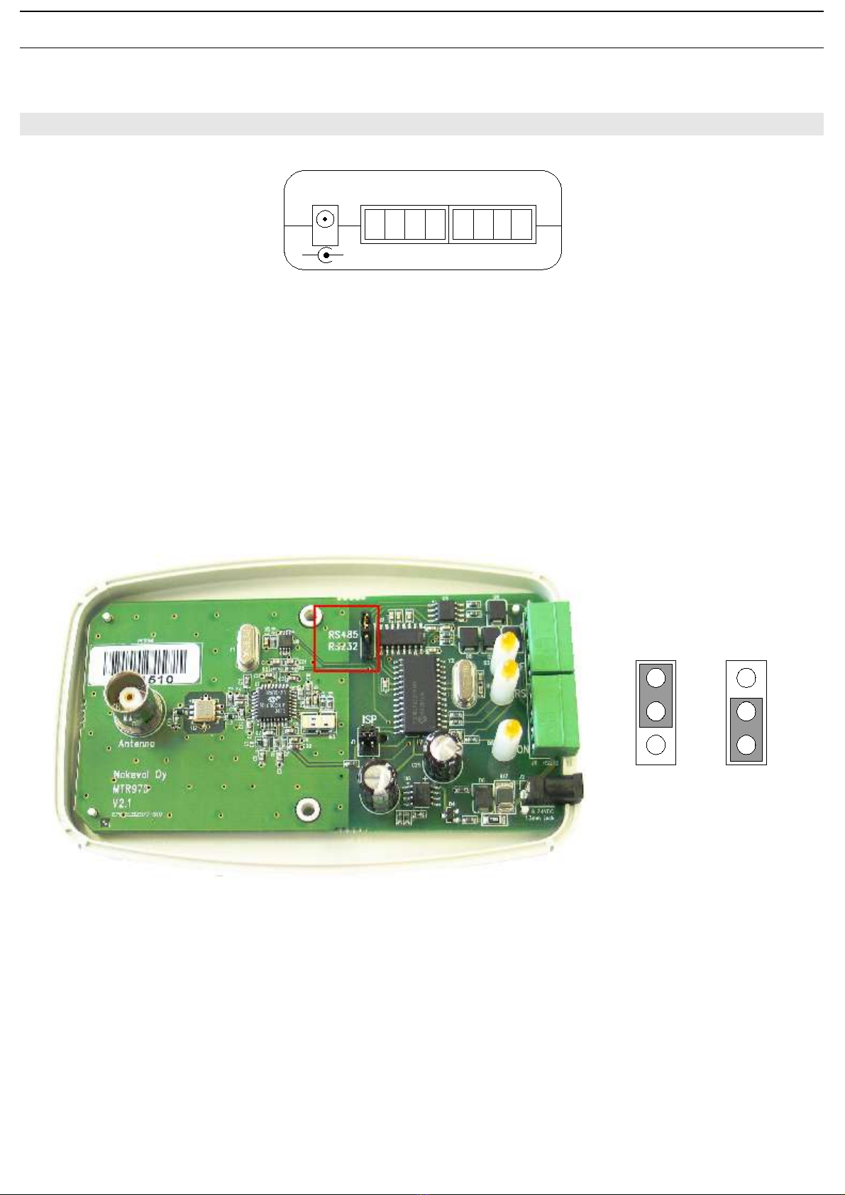
Settings
Connection: RS-485 or RS-232
Protocol: Nokeval SCL-Meku 1
So tware: Mekuwin or Windows 98...XP
Other
External Dimensions
case: 115 mm x 75 mm x 25 mm
antenna: 87 mm, ∅ 14 mm
Regulations
EMC directive
• EMC immunity EN 61326
• EMC emissions EN 61326, class B
R&TTE directive
• EN 300 220 Receiver class 3
• EN 301 489
• EN 300 339
3

INSTALLING
Connections
The supply voltage 9...30 VDC is connected using 1.3 mm DC jack (centre connector positive) or by using detachable screw
post connector terminals 1 (+) and 2 (-) or 5 (+) and 6 (-). All supply voltage connectors are internally connected. The receiver
is protected against wrong polarity o the supply voltage. The supply voltage's negative terminal is also used as ground or RS-
485 and RS-232.
RS-485 bus is recommended. I necessary RS-485 inter ace can easily be added to a computer by using Nokeval DCS770 or
DCS771 USB - RS-485 converter or RCS770 USB/RS-232 – RS-485 converter. RS-485 bus is connected to terminals 7 (D1)
and 8 (D0).
When using Nokeval 711 and 721 serial converters, terminal 7 (D1) is connected to serial converter's terminal A and terminal 8
(D0) to terminal B. When using serial converters not manu actured by Nokeval, connect receiver's terminal (D1) to serial
converter's terminal B and terminal 8 (D0) to terminal A.
RS-232 is connected to terminals 2 (GND), 3 (RxD) and 4 (TxD). By de ault the device is jumpered to use RS-485 bus, so i RS-
232 is required the jumper must be set to RS-232 position. To do this, screw o the two screws rom the bottom o the case and
remove the top part o the case. Set the jumper to RS-232 position and close the case.
The antenna is connected to the BNC connector at the top side o the case. First align the emale connector's two guideposts to
the male connector's channels. Then press the BNC connector in and lock the connector by rotating the male connector's outer
ring clockwise. I needed, the antenna can be removed by rotating the ring counter clockwise and then pulling out the antenna.
4
1 2 3 4 5 6 7 8
RS-485RS-232POWER
+ - RxD TxD + - D1 D0
+
-
default
RS-485 RS-232

Installation site
To achieve the best signal levels place the MTR970 receiver as close to the transmitters as possible. The receivers RS-485
connection and wide supply voltage range enables the use o connection wires up to 1000 meters in length. In addition, multiple
receivers can be connected to RS-485 bus to increase the coverage area. Transmission is received when at least one receiver
receives the transmission without errors.
MTR970 is designed or desktop use but it can also be installed, or example, upside down to a ceiling or to a cable rack. The
best installation site or the device is a airly large grounded metal sur ace that has little surrounding metal walls. The best signal
levels are achieved when there is a line o sight to transmitters. Walls and obstacles attenuate the signal and there ore decrease
the coverage area. On the other hand, metal sur aces can also cause re lections and increase the coverage area. The device
can be secured using plastic cable ties or two-sided tape. Do not use metal astenings i they cover any part o the case.
5

SETTINGS
Connection settings
Use Mekuwin program to con igure the device. You can download Mekuwin rom Nokeval's web site or ree.
De ault communication settings or con iguration:
• Baud rate 9600
• protocol SCL
• address 0
Menu
Menu o MTR970
Serial submenu (Ser)
Serial communication settings. Note that the changes here do not a ect until the device is rebooted.
Address
SCL address selection. Allowed addresses are 0...123.
Baud
Baud rate selection. Options are 300, 600, 1200, 2400, 4800, 9600 and 19200.
Receive submenu (Rcv)
CRCChk
I selected, CRC checksum o received data packets is checked and corrupted packets are rejected. The setting is on by de ault
and there is no reason to disable the setting.
CH1ID
One MTR series transmitter (except MTR260) can be de ined to act as channel one. When MTR970 receives ”MEA CH 1 ?”
command it sends latest received data rom transmitter that has been mapped to channel one. To map a device to channel one,
set the transmitter's ID to CH1ID value.
6
Con
Ser
Rcv
Rcv
CRCChk
CH1ID
Ser
Addr
Baud

SCL PROTOCOL
A more detailed description o the Nokeval SCL protocol can be downloaded rom Nokeval www pages
http://www.nokeval.com/manuals/sclmanual.pd . Some additional commands have been added to SCL protocol or MTR and
RTR series devices that are not covered by the general SCL manual. These commands are explaided in the list below.
MTR970 supports the ollowing SCL commands:
TYPE ?
Returns the model name and so tware version.
SN ?
Returns the device's serial number, or example ”A123456”
MEA CH 1 ?
Returns the last received value rom the device that is de ined as ”channel 1”.
DBG 1 ?
Returns the oldest unread data packet rom the bu er.
DBR 1 xx ?
Returns a data packet rom the ring bu er location xx.
DBX
Clears the ring bu er.
DBS 1 ?
Returns the size o the ring bu er.
7

8
Yrittäjäkatu 12
7100 Nokia
Finland
Tel + 58 424800
Fax + 58 422066
www.nokeval.com
Table of contents
Other Nokeval Receiver manuals
Popular Receiver manuals by other brands

Teleco
Teleco TVSTRD868NT24 manual

Silex technology
Silex technology X-5 Frequently asked questions

Harman Kardon
Harman Kardon AVR 135 Product View

Pioneer
Pioneer VSX-819H-K - AV Receiver - Gloss operating instructions

Itegra
Itegra DTR-30.6 Advanced manual

SHENZHEN FLYING INDUSTRY DEVELOPMENT
SHENZHEN FLYING INDUSTRY DEVELOPMENT S2PU-AC380-ANT3 quick start guide