7
Opening the case
Modules can be detached from each other by pressing the locking latches on the sides of the enclosure and
at the same time pulling the modules apart.
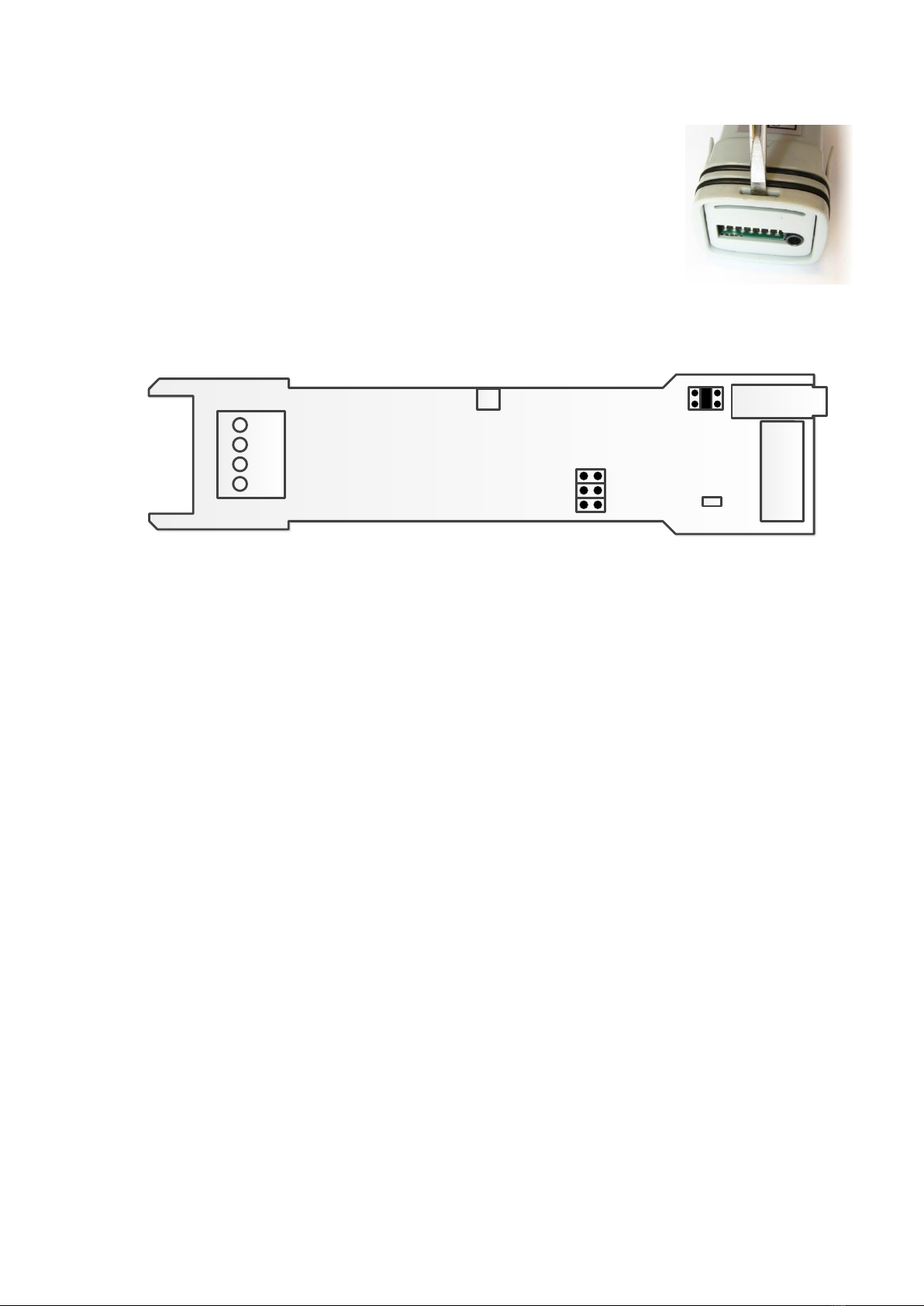
For receiver operation the serial module must be opened for RS485 and power
cables installation. Serial module can be opened by gently pushing a screwdriver
into the slot that holds the cover plate.
When the cover plate is removed, the circuit board can be pulled out of the
enclosure.
Connections
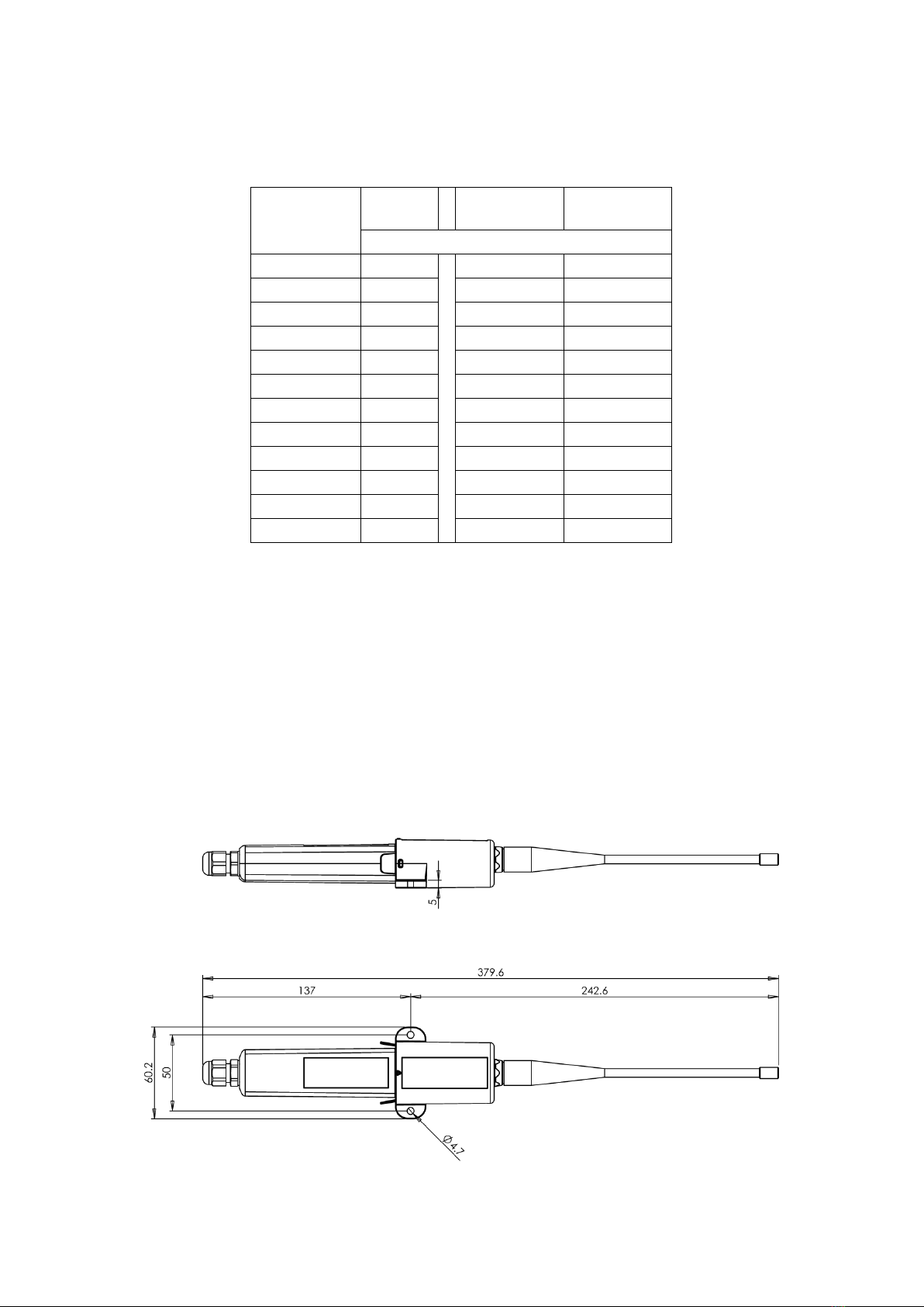
FT20 serial module has a 4-pin terminal block for power supply and RS-485 connection. Serial module
features also a round 3.5 mm POL programming connector jack found on many other Nokeval products as
well. FT20 radio module contains BNC type antenna connector.
Power supply
The supply voltage range is 8...30 VDC and is connected to terminals 1 (+) and 2 (-). Power demand is 50
mA. FT20 is protected against wrong polarity of the supply voltage.
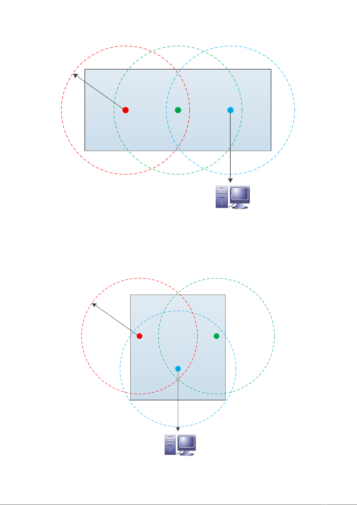
RS-485 serial bus
RS-485 is used when the device operates as a receiver. RS-485 interface can easily be added to a computer
by using Nokeval DCS770 or DC771B USB - RS-485 converter or RCS770 USB/RS-232-RS-485 converter. If
you use DC771B converter, no external power supply needed (DC771B's power supply should be set to
10V). RS-485 bus is connected to terminals 3 (D1) and 4 (D0). The supply voltage's negative terminal 2 (-)
can also use as ground for RS-485.
The RS-485 bus consists of a bidirectional half-duplex twisted data pair and a common wire. The cable
should be shielded, the shield earthed at one point. The nominal impedance should be approx. 100-120 Ω.
The length of an RS-485 bus can be up to 1 km and it can be connected to 32 devices, more can be
connected via bus repeaters. If the bus is long (say more than 100 m), it is recommended to terminate the
first and last device on the bus (set the ”RS485 AC term” jumper to ”on” position).
The polarity of the data pair is important. Modbus specifications call the positive idling line D1, but it is also
commonly known as +, B, and A. Correspondingly the negative idling line is -, A, or B.
The bus needs one device that gives a small voltage between the data wires when no device is transmitting
on the bus. This is called biasing or fail-safing. The master device is usually the natural choice for biasing.