PRO
Radio
Memory
Error
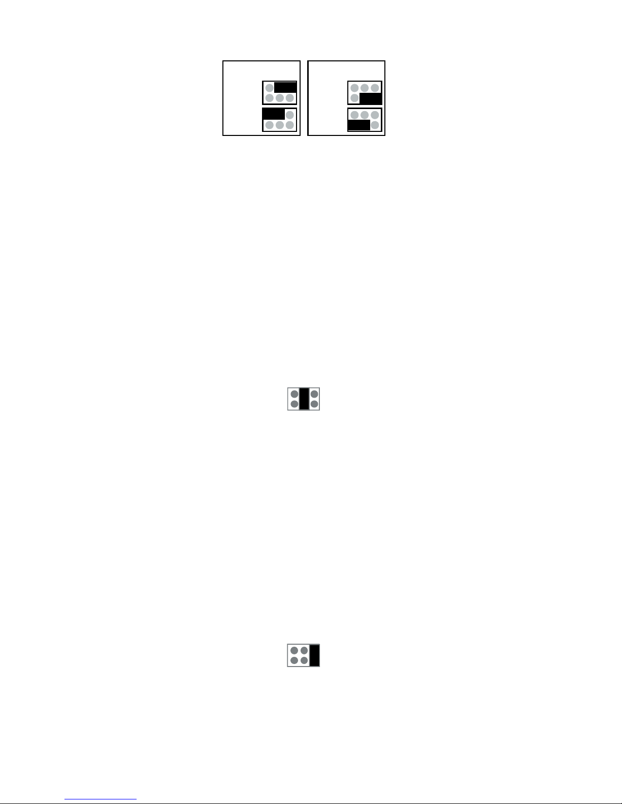
J11
J7
1 2 3 4
+
-
+ - D1 D09V
RS RF
USB
5 6 7
- RxD TxD
Power LED
5
Indicator lights
Indicator lights
PRO: Means that device is operating.
RADIO: Means that device is processing serial communi-
cation command.
MEMORY: Means that device is writing data to flash mem-
ory.
ERROR: When power is applied to the device first time er-
ror is light almost certainly, since the real time clock is out
of time in device. This error disappears when new time is
set to clock either automatically with PromoLog or manu-
ally with MekuWin. Note! In case that flash logging is dis-
abled the time loss of real time clock does not lit error led.
Other than above this normally means that there is some
error. Meku monitor will give more descriptive error infor-
mation. Possible error causes are: flash memory broken,
radio coprocessor not responding, real time clock circuit
not responding or real time clock time has been lost, or
EEPROM memory has been cleared.
If the error is caused by EEPROM memory, then error goes
off when new settings are saved to EEPROM.
If reason is that real time clock has lost time, error is con-
tinuously on, until new time is set to device.
All other errors will be automatically cleared if the reason
for error disappears, but if error light is on continuously
and cause of error is not some of the above mentioned
then the device must be sent for service.
Side indicator lights
RS: Informs about internal communication of device. This
should blink constantly.
RF: Informs about received radio packets. This light should
blink randomly depending on the number of radio transmit-
ters within range.
Behind: Power led is positioned behind the two lights, and
it lights if the device is powered. This light is visible when
viewed directly from the front.