Nokta MAKRO Racer 2 User manual


READ CAREFULLY BEFORE OPERATING THE DEVICE!
LEGAL DISCLAIMERS
Comply with the laws and regulations in force within the area while using the device.
Do not use the device in protected or archeological sites and military zones. Notify
any historical and cultural artifacts you find to the concerned authorities.
WARNINGS
RACER 2 is a state-of-the-art electronic device. Do not assemble or operate the
device before reading the user manual.
Do not keep the device and search coil under extremely low and high temperatures
for extended periods. (Storage Temperature: - 20°C to 60°C / - 4°F to 140°F)
Do not immerse the device and its accessories (except for the search coil) in water or
keep them in excessively humid environments.
Protect the device against impacts that may occur during shipping in particular.
RACER 2 may only be disassembled and repaired by authorized service centers.
Disassembling the device for any reason voids the warranty.

Table of Contents
Assembly.........................................................................................................................................................
General Description of the Device........................................................................
Battery Details........................................................................................................................................
Display................................................................................................................................................................
Correct Use..................................................................................................................................................
Quick Guide................................................................................................................................................
Menu...........................................................................................................................................................
Modes....................................................................................................................................................
Ground Balance.....................................................................................................................
Gain, iSAT and Threshold........................................................................................
Target ID and ID Filter ...............................................................................................
Pinpoint........................................................................................................................................................
Target Distance................................................................................................................................
Swinging Speed and Target Identification..........................................
Large or Near-Surface Targets..................................................................................
False Signals and Reasons..............................................................................................
Magnetic Mineralization Indicator...................................................................
Rocks and Searching in Rocky Terrains...........................................
Tracking and Effects of Rocks....................................................................................
Metals Under Rocks........................................................................................................
Searching in Shallow Water and Beach.....................................................
Messages....................................................................................................................................................
Technical Specifications.....................................................................................................
1
2
3
4
5
6
7-12
13-14
15-18
18-19
20-21
22
23
23
23
23
24
24-25
25
25-26
26
27
28
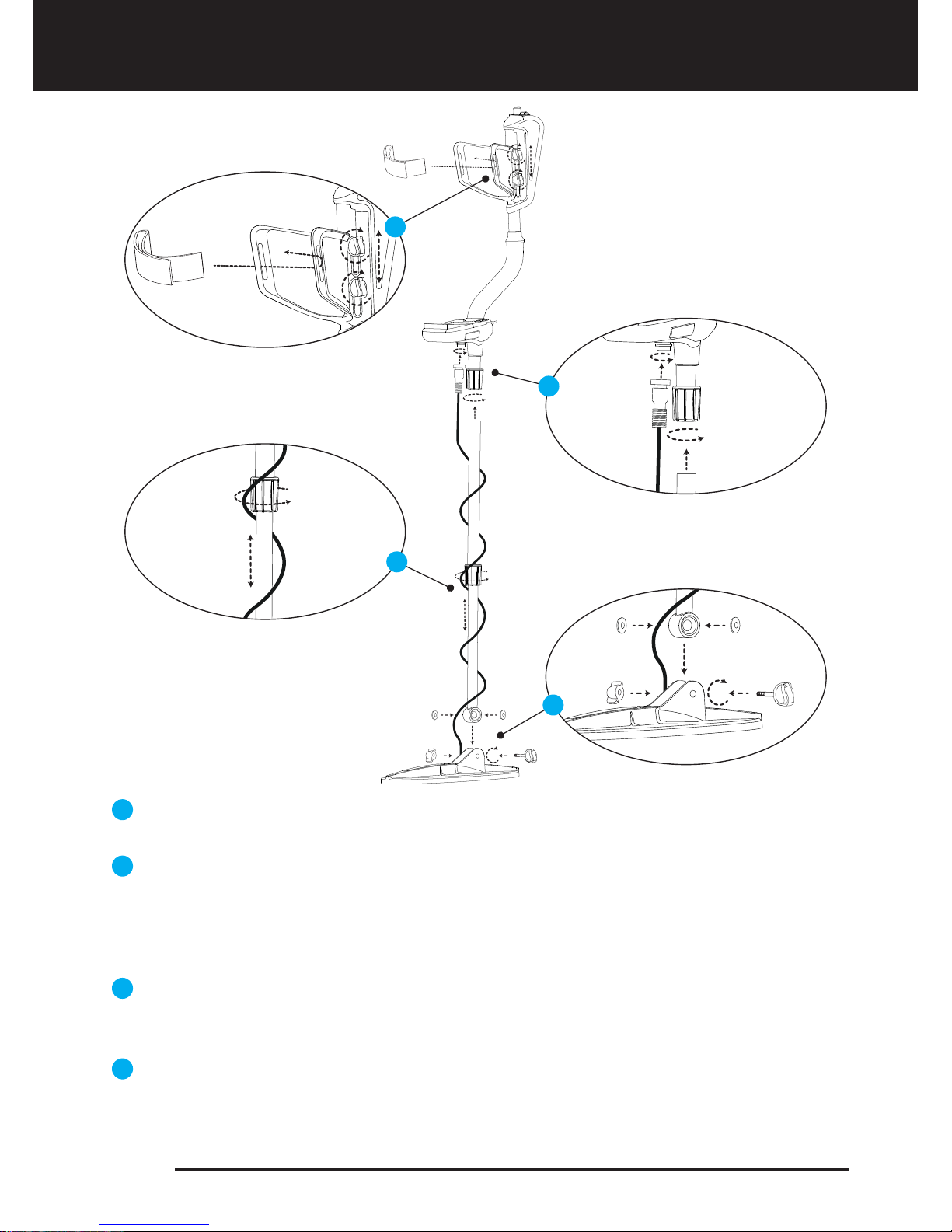
Insert the washers as shown on the telescopic shaft. Install the telescopic shaft to its
location on the search coil. Secure by tightening the screw and nut.
Loosen the twist lock before mounting the telescopic shaft to the upper rod. Press down
the pin and engage the pieces together and tighten the twist lock after the pin is clicked
into the hole. Wind the cable of the search coil on the telescopic shaft without stretching
too much. Plug the connector on the cable to the search coil input socket on the system
box and secure by tightening the nut.
Loosen the twist lock of the telescopic shaft to extend or shorten it. Adjust the length
of the shaft by keeping the pin located on the rear pressed down and clicking the pin
in any of the holes. Secure by tightening the twist lock.
Insert the armrest band through its slot as shown in the figure. Loosen the screws and
adjust the armrest position to your comfort by sliding it down or up and secure by
tightening the screws.
1
2
3
4
Assembly
Page 1
1
3
2
4

General Description of the Device
Display showing all settings and information
Keypad for navigation among menu options and changing the device settings
Ground balance and pinpoint trigger
Speaker
Battery compartment cover
On /Off and volume adjustment button
Wired headphone jack
Search coil connector socket
LED flashlight
1
2
3
4
5
6
7
8
9
1
2
3
4
5
6
7
8
9
Page 2
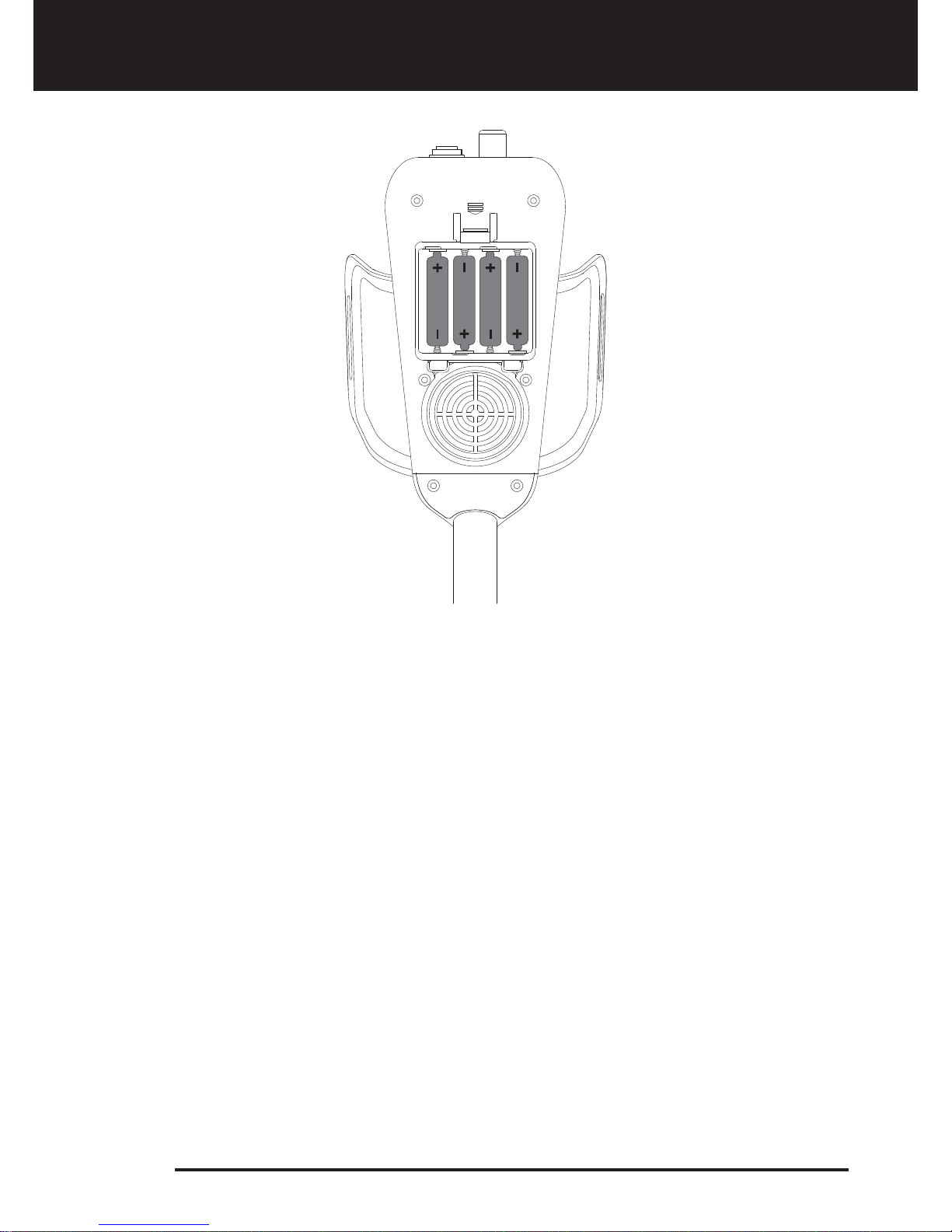
Battery Details
The device is supplied with 4 pieces of AA Alkaline batteries.
To remove the battery compartment cover, press on the latch and pull out. Insert the
batteries observing correct polarity of + (plus) and - (minus).
The device can be used for approximately 20-25 hours when the batteries are fully
charged. Operating time of other brands and types of batteries available on the market
may vary.
AA Alkaline batteries are recommended for the best performance. Good quality Ni-MH
rechargeable batteries can be used, too. Rechargeable batteries with high mAh (capacity)
ratings offer extended operating times than batteries with lower rating.
Low Battery Level
Battery icon on the display shows the battery life status. When the charge decreases, the
bars inside the battery icon decrease, too. "Lo" message appears on the display when the
batteries are depleted and the device shuts down after a short period.
Page 3
4 5
6
3
2
7
8
9
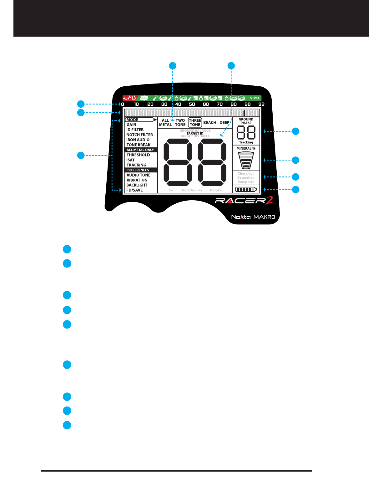
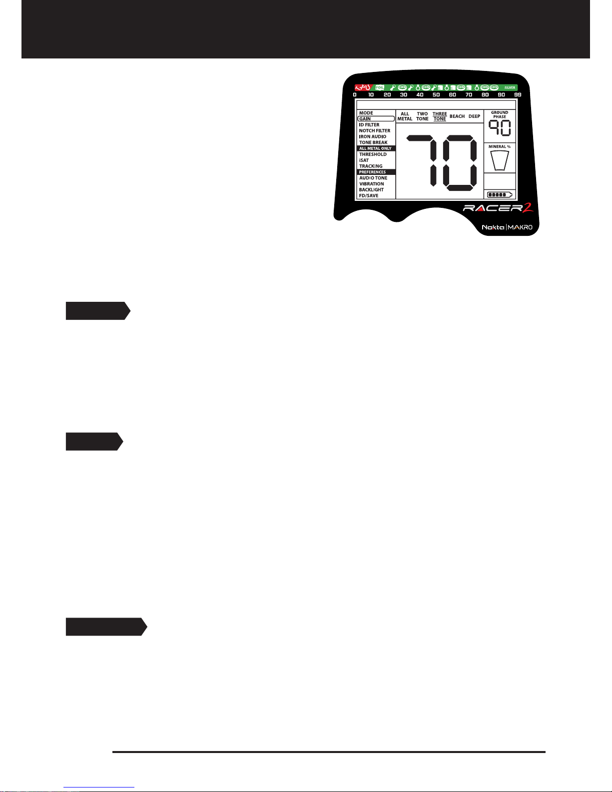
Display
Menu providing access to all settings of the device
Cursor indicating the ID of the detected target and its position on the ID
scale. It also indicates the IDs masked by ID FILTER and NOTCH FILTER as
well as the tone breakpoints.
Target ID scale
Search mode indicator
Section which shows the TARGET ID during search, the ground balance
value during ground balance adjustment and the estimated target depth
during the pinpoint process. Also, the numeric value of any setting selected
from the menu is displayed in this field.
Section which shows the fine tuning value during ground balance
adjustment and current ground balance value during search. TRACKING
on/off status is also shown in this section.
Magnetic mineralization indicator
Section which shows the warning messages
Battery level indicator
1
3
4
5
6
7
8
9
2
1
Page 4
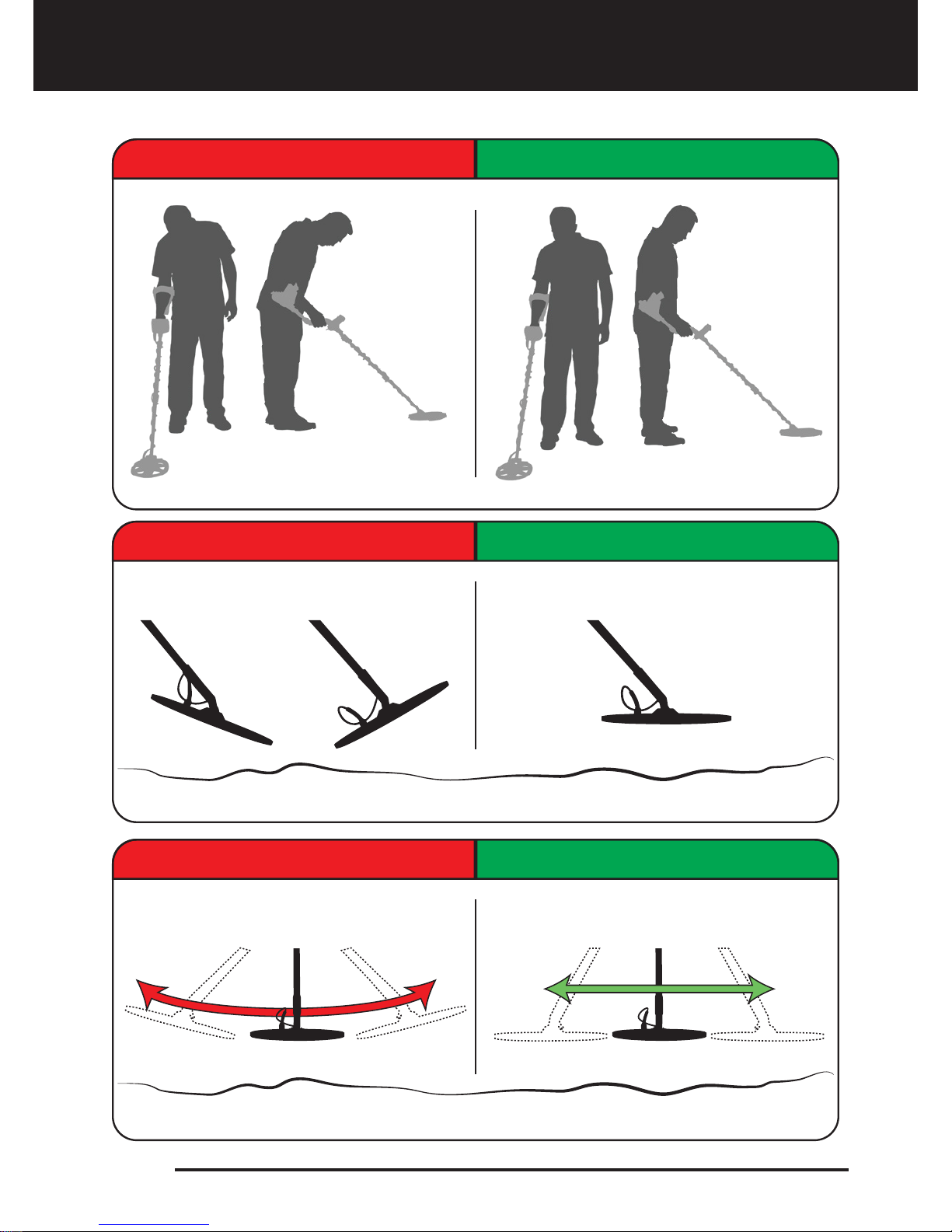
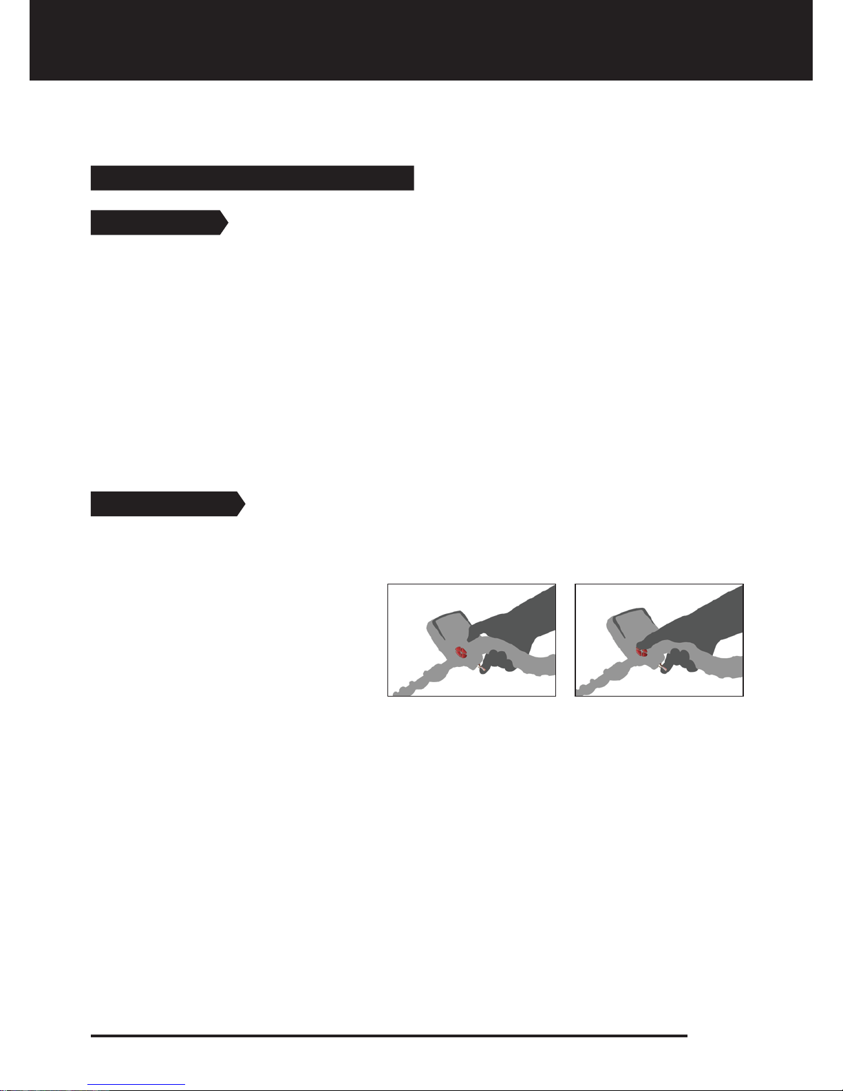
Correct Use
Incorrect Handling Correct Handling
Incorrect Use Correct Use
Incorrect Use Correct Use
Page 5

Assemble the device as per the instructions on page 1.
Insert the batteries by paying attention to +/- polarity.
Rotate the on/off switch located behind the device clockwise to turn on the
device. This switch also adjusts the volume.
When the device is turned on, it will start in the Three Tone mode. You can
change the mode based on the area that you are searching. For instance, if
your search will be performed on wet beach sand, select the Beach mode.
To ground balance, push and hold the trigger forward and pump the search
coil up and down 3cm (1.2'') above the ground until a “beep” sound is heard.
You can increase the GAIN if needed. Increasing the gain will offer you
greater depth. However, if the surroundings or the ground cause excessive
noise in the device, you need to lower the gain setting.
Testing with various metals is useful for getting familiar with the sounds
produced by the device.
Based on the IDs of the metals you don't want to detect, you can adjust the
ID FILTER and ignore those metals. For instance, if you don’t want to detect
ferrous metals with 4 ID, you can set the ID FILTER to 5.
If you are detecting in a very trashy area and the device is getting too many
iron signals, instead of ID FILTER you can use IRON AUDIO to lower or
completely turn off the iron audio. This will provide more depth.
You can mask certain Target IDs using the NOTCH FILTER. For example, if
you don't want to detect metals with IDs 31-32, you can simply block these
IDs with NOTCH FILTER and enable the device to ignore these metals during
searching.
If you wish, you can adjust the tone break points of the device with the
TONE BREAK feature and change the frequency of the tones using the
AUDIO TONE setting.
You can now start searching.
Since your device operates with the motion principle, swing the search coil
right and left maintaining 5cm (2") distance above the ground. If the search
coil does not move, the device will not provide any warning tones even if
the coil is over a metal target.
When a target is detected, the ID of the target is displayed on the screen
and the cursor indicates its position on the ID scale. The device also
produces a warning tone based on the search mode selected.
Upon target detection, you can pinpoint the exact location of the target by
pulling and holding the trigger back.
1
3
4
5
6
7
8
9
10
11
12
13
14
15
2
Quick Guide
Page 6
MODE
5 search modes adapted to different ground conditions and target types are offered by
RACER 2. Names of the search modes are defined as ALL METAL, TWO TONE, THREE TONE,
BEACH and DEEP on the menu screen. You can easily switch between the modes by using
the direction keys during your search. The name of the selected mode is shown framed on
screen. While in settings, the selection cursor appears on the selected setting and the
current mode name is underlined. For more details, please read the MODES sections
carefully. (page 13-14).
GAIN
It is the depth setting of the device. It is also used to eliminate the ambient
electromagnetic signals from the surrounding environment and noise signals transmitted
from ground.
Gain setting range is 01-99 and pre-defined for each mode. All modes start at default
settings. They can be manually modified when necessary. Gain adjustment applies to the
selected mode; the modified setting does not affect the gain setting of the other modes.
NOTE: In case of the coil overloading due to very high mineralization, decreasing the gain
will overcome the situation.
For more details, please refer to GAIN, iSAT and THRESHOLD section.
ID FILTER
TARGET ID is the number produced by the metal detector based on the conductivity of the
metals and gives an idea to the user about what the target may be. Target ID is shown with
two digits on the display and ranges between 00-99.
Select a setting from the menu by using the
up/down buttons. The value of the selected
setting is shown on the display. You can change
the value by using the + and - buttons.
If up/down and +/- buttons are kept pressed for
a certain period, options and values change
more rapidly.
If no button is pressed for a while after selecting a
setting or changing its value, the device
automatically returns to MODE option. Pulling the
trigger enables you to return to the MODE option
without waiting (except for Notch Filter, Tone Break and Audio Tone options).
NOTE: Certain settings are mode specific and thus cannot be selected in other modes. For
details, please read the explanations about the settings carefully.
Menu
Page 7

ID FILTER is the ability of the device to ignore all metals below a certain TARGET ID. In the
ID FILTER process, the filtered ID range is shown with lines on the ID scale and every 2
consecutive IDs are represented with 1 line. For example, if you set the ID FILTER to 30, 15
lines will be shown between the 0-30 ID range on the scale and the device will not produce
a warning tone for any metals with IDs between 0-30.
ID FILTER cannot be used in the ALL METAL mode. It is pre-set for all the other modes. See
TARGET ID and ID FILTER section for further information (page 19-20).
NOTCH FILTER
NOTCH FILTER is the ability of the device to discriminate single or multiple TARGET IDs.
Although NOTCH FILTER may seem similar to the ID FILTER at first glance, these two
settings have different functions. While the ID FILTER filters out all IDs between 0 and the
set value, the NOTCH FILTER filters IDs individually.
With the NOTCH FILTER you can reject a single ID or multiple IDs at the same time. This
process does not affect any IDs below or above the selected IDs. For example, you can filter
out IDs between 31-35 as well as 50 simultaneously.
HOW TO USE THE NOTCH FILTER:
When NOTCH FILTER is selected on the menu, first the current ID FILTER value is displayed
on screen and the filtered ID range will be shown on the scale with lines. For example, if the
ID FILTER is set to 15, when you select NOTCH FILTER, number 15 will be displayed on
screen corresponding to 8 lines on the scale (every 2 consecutive IDs are represented with
1 line). NOTCH FILTER cannot be used within the ID FILTER range. In other words, if the ID
FILTER is set to 15, NOTCH FILTER can only be applied to IDs 16 or higher. If you want to
NOTCH FILTER IDs 15 or below, first you need to change the ID FILTER value.
The NOTCH FILTER rejects or accepts IDs with the help of the cursor at the top of the screen.
To move the cursor on the scale, plus (+) and minus (-) buttons are used. The cursor blinks
while it is moving on the scale. When you are on the first ID that you want to reject, pull and
release the trigger once. This ID is now rejected and it is shown on the screen with a line. If
you want to reject multiple IDs, continue to press the plus (+) or minus (-) button. If
non-consecutive IDs want to be rejected, pull and release the switch once to have the
cursor blink for navigation on the scale and repeat the process above. The cursor will
appear where you left it at the next time you use the NOTCH FILTER.
To give an example; let's say you want to reject IDs between 20-25 and the cursor is at 10.
Press the plus (+) button until you reach number 20.Then pull the trigger once and release.
Number 20 will be marked with a line. When you reach number 25 using the (+) button
again, IDs between 20-25 will be filtered out and they will be shown on the ID scale with 3
lines (every 2 consecutive IDs are represented with 1 line).
To accept back the filtered IDs, select NOTCH FILTER in the menu. The cursor will appear
where you last left it at. Using the plus (+) or the minus (-) button, select the ID you want to
accept and pull the trigger once. Then, using the plus (+) or minus (-) button again, unfilter
the IDs back in. 1 line will be erased for every 2 consecutive IDs accepted.
Page 8
Menu

NOTCH FILTER adjustment applies to the selected search mode only. The change does not
affect the other modes. Since there is no discrimination in the ALL METAL mode, this
setting is inactive in this mode.
IRON AUDIO
It adjusts or turns off the volume of the low iron tone.
IRON AUDIO range is 00-10. 10 is the maximum level. As you lower it, the volume of the
warning tone the device produces for ferrous metals will decrease. At 00 level, the iron audio
will be silenced. In other words, the device will detect ferrous targets, the Target ID will be
displayed on the screen but the device will not produce any warning tone.
IRON AUDIO adjustment applies to the selected search mode only. The change does not
affect the other modes.
Since there is no discrimination in the ALL METAL mode, this setting is inactive in this
mode.
TONE BREAK
It is used to adjust the break points of the target response tones on the TARGET ID range.
As the factory default, in TWO TONE, BEACH AND DEEP modes the device emits a low tone
for ferrous metals (Fe) with target IDs equal to or less than 10 and a high tone for gold and
non-ferrous metals (Gold/Non-Fe) with IDs 11-99. In the THREE TONE mode, the device
emits a low grunt tone for ferrous metals with target IDs equal to or less than 10, a low
tone for gold and non-ferrous metals with IDs 11-70 and a high tone for non-ferrous metals
with IDs 71-99. By using the TONE BREAK feature, you can change the point where the low
tone changes into the high tone.
To use the TONE BREAK, first select this setting in the menu. The names of the metal groups
corresponding to the IDs mentioned above will appear at the bottom of the screen. The
TONE BREAK point of the metal group will be shown on the screen and the cursor at the
top will also point to it on the ID scale. In the THREE TONE mode, there are 2 break points
(Fe and Gold/Non-Fe). To select either one, pull the trigger once and release and the
selection will be framed. There is only one break point (Fe) in the other modes. To change
the value of the break point, plus (+) or (minus) button is used.
To give an example for the above explanation; let's say you are in the THREE TONE mode
and you want to change the TONE BREAK points. First, select TONE BREAK in the menu. Fe
and Gold/Non-Fe will appear at the bottom of the screen and Fe will be framed. The default
value of 10 will also be displayed on the screen. Using the plus (+) or the minus (-) button
change this number to any value you want. Let's say you increased it to 40. Then, pull the
trigger once to select the Gold/Non-Fe. Let's say you decreased the default value of 70 to
50. In this case, the device will produce a low, grunt iron tone for all metals with IDs equal
to or less than 40, a low tone for metals with IDs 41-50 and a high tone for metals with IDs
greater than 50.
TONE BREAK adjustment applies to the selected search mode only. The change does not
affect the other modes.
Page 9
Menu

THRESHOLD
ALL METAL ONLY
This setting is used to adjust the humming sound, referred to as the threshold sound,
which is continuously heard in the background in the All Metal mode. It is used to increase
the target signal, in other words, the depth of the device. For more details, please read
Gain, Threshold and iSAT section.
AUDIO TONE
PREFERENCES
Allows you to change the target warning tones and the threshold sound according to your
preference. For each metal group (Fe, Gold/Non-Fe, Non-Fe) the frequency can be adjusted
between 100 Hz (10) and 700 Hz (70).
When AUDIO TONE is selected in the menu, names of the metal groups mentioned above
will appear at the bottom of the screen and the selected one will be framed. To select
another group, just pull the trigger once. Then use the plus (+) or the minus (-) button to
change the frequency.
iSAT
For the All Metal mode to perform accurately, a stable threshold sound is necessary.
Changes in mineralization and soil structure may cause a rise or fall in the background hum
and disrupt the threshold's stability which will result in losing signals of small metals. iSAT
feature maintains the steadiness of the threshold by adjusting the speed the device
recovers its threshold sound.
iSAT consists of 10 levels . The device will start at level 4. It is recommended that iSAT
should be increased in high-mineralization and decreased in low mineralization. For more
details, please read Gain, Threshold and iSAT section.
TRACKING
Although the Tracking feature appears under the ALL METAL mode settings, it is actually a
common feature to all modes so when it is turned on, it becomes active in all modes. The
reason it appears under the ALL METAL mode settings is that the use of tracking is
recommended in the ALL METAL mode and not in the discrimination modes.
When tracking is active (01 position), the device continuously tracks the changing ground
structures and automatically reconfigures the ground balance setting. The invisible
changes in ground affects the detection depth as well as the discrimination ability of the
device so it is possible to operate the device at higher performance using this feature
under suitable ground conditions. Please refer to page 25 for more information on
TRACKING.
When TRACKING is activated, ''Tracking'' will be displayed in the GROUND PHASE box at
the upper right corner of the screen.
Page 10
Menu

AUDIO TONE adjustment applies to the selected search mode only. The change does not
affect the other modes.
VIBRATION
This feature provides feedback to the user by producing a vibration effect when a target is
detected. It can be used independently or together with the warning tone. When warning
tone is disabled all feedbacks are provided to the user as vibration only during target
detection.
Vibration setting is adjusted within the range of 00-05. When it is switched to 0, vibration
feature is completely disabled. If the vibration is at 01 level, the device provides long
vibration signals and at 05 it provides short vibration signals. The magnitude of the
vibration effect can vary according to the depth of the target and the swinging speed. This
setting is common in all search modes; change made in any mode also applies to the other
modes.
Vibration is not felt in the All Metal mode with weak signals; it will be felt as the signal gets
stronger. In other words, vibration does not start at the depth that warning tones are heard
but at a lesser depth. Therefore, if you perform search only with vibration and warning
tones of the device are off, you can miss weaker and deeper signals.
Vibration speed is constant in the pinpoint mode and cannot be adjusted. Vibration is off
at 0 position. 01-05 values provide the same level of vibration in the pinpoint mode. When
vibration is used in the pinpoint mode, vibration speed increases as the target is
approached and it reaches the maximum level over the center of the target.
BACKLIGHT
It enables you to adjust the keypad and display backlight level according to your personal
preferences. It ranges between 0-5 and C1-C5. At 0 level, the keypad and display backlight
are off. When set between 1-5, it lights up only for a short period of time when a target is
detected or while navigating the menu and then it goes off. At C1-C5 levels, it will light up
constantly. As the constant operation of the backlight will affect power consumption, it is
not recommended.
The backlight setting is restored to the final saved setting when the device is turned off
and on again. This setting is common in all modes; change made in any mode also applies
to the other modes.
Factory Default /Save (FD/Save)
With the FD/Save feature of the RACER 2, you can save your settings or restore factory
defaults. Save function saves all settings except for the ground balance and tracking. The
device starts in the last mode where the save function was performed. For example, you
changed the settings of both the All Metal mode and the Deep Mode and you saved the
settings while in the Deep mode. Your device will start in the Deep mode upon next start up.
To save your settings, select FD/Save on screen. SA will be displayed. To confirm, pull the
trigger once and release. SA will stay on screen for a short period of time and it will disappear
when saving is completed.
Page 11
Menu
To restore factory defaults, select FD/Save on screen and press the minus (-) button. FD will
be displayed. To confirm, pull the trigger once and release. FD will stay on screen for a short
period of time and it will disappear when the process is completed.
FREQ. SHIFT
Other Settings Not Shown on Screen
It is the setting which enables you to change the operating frequency of the device. It is
used to eliminate the electromagnetic signals that the device receives from another
detector which operates in the same frequency range nearby or from the surroundings. If
too much noise is received when the search coil is lifted in the air, this may be caused by
the surrounding electromagnetic signals or too much sensitivity. In this case, first reduce
the GAIN. If the noise is not eliminated, you can choose to shift the frequency. The device
offers 5 different frequencies. Default setting is frequency 03.
To shift the frequency, keeping the trigger pulled back, simply press the plus (+) or the
minus (-) button.
IMPORTANT! Frequency shift may impair performance. Therefore, it is suggested that you
do not shift the frequency unless it is required and operate it with the default settings.
LED Flashlight
It is the light used for lighting the scanned area while performing search at night or dark
locations. LED flashlight does not operate when the device is off. It is recommended to turn
it on when necessary since its operation consumes battery charge.
Keeping the trigger pulled back, press
the up button once to activate the LED
flashlight. Repeat the same procedure
to turn it off.
Page 12
Menu

MODES
Page 13
Discrimination Modes (Two Tone, Three Tone, Beach, Deep)
Different than the All Metal mode, these modes do not have a background sound. The
device only provides a warning tone when a target is detected. A crackling noise can be
heard if gain is not at the right level in these modes. Therefore, the gain adjustment in
these modes should be performed in a location without metals and when the device is
silent.
Some of the features of the discrimination modes are similar, however, there are minor
behavioral differences between them. ID FILTER, NOTCH FILTER, IRON AUDIO and TONE
BREAK are frequently used common features in these modes. ID FILTER value is preset by
the factory for these modes. You can modify these settings if you want according to the soil
conditions where you are searching.
Two Tone Mode
It is the deepest mode after the DEEP mode among the discrimination modes. It is
recommended especially for relic and coin hunting. It produces good results particularly
on clean sites which do not contain waste metal. More depth can be obtained on sites
which are rocky or contain waste metals by using the ID FILTER and NOTCH FILTER features
and swinging the search coil more slowly (one right/left pass per approximately 1 second).
ID FILTER value is set to 03 as a default value. You can modify this value according to the ID
of the target you don’t want to detect.
In the Two Tone mode, the device produces a low tone for ferrous targets with IDs between
0-10. For gold/non-ferrous targets with IDs 11-99, it produces a high tone which increases
in pitch as the coil approaches the target. By using the TONE BREAK feature, you can adjust
the break points of the target response tones on the TARGET ID range.
It is recommended that you perform tests with mineral rocks and different metals before
using the device in the field in order to get familiar with the warning tones of the device.
All Metal
It is the deepest mode of the device. Different than the other modes, this mode features a
threshold tone which is continuously heard in the background.
The device does not discriminate targets while in the All Metal mode and detects all
targets (metal, mineralized rocks etc.). ID of the detected target is shown on the display
(except for negative hot rocks) and the same warning tone is provided for all targets. The
warning tone increases in pitch as the coil approaches the target.
Gain, threshold and iSAT settings in this mode are set to default values which provide the
best performance on different terrains. You can modify these settings based on ground
conditions.
ID FILTER, NOTCH FILTER, IRON AUDIO AND TONE BREAK features not active in the All Metal
mode. Therefore, these settings cannot be selected in the menu.
We recommend using the All Metal mode when discrimination is not important and not
using it in heavy trash areas or areas containing many hot rocks.

Page 14
MODES
Three Tone Mode
This is the 3-tone discrimination mode designed for coin hunting especially in trashy sites. In
this mode, the device produces a low, grunt tone for ferrous targets with 0-10 IDs, a low tone
for gold and non-ferrous metals with IDs 11-70 and a high tone for non-ferrous metals with IDs
71-99 such as silver, brass and copper. By using the TONE BREAK feature, you can adjust the
break points of the target response tones on the TARGET ID range.This mode is ideal to use in
fields with different types of metals enabling you to search faster with audio discrimination.
You can search without detecting unwanted targets in this mode by using the ID FILTER
and NOTCH FILTER feature as in the Two Tone mode. ID FILTER value is set to 03 as a default
value. It is recommended to modify this value according to the type of target.
Beach Mode
It is the special mode of RACER 2 developed for conductive grounds (wet sand beach,
grounds with alkali soil etc.). The feature of this mode is its ability to ignore iron and similar
targets in this group and to perform ground balance on any type of ground. While the
device performs ground balance in the range of 40-90 automatically in the other
discrimination modes, the device ground balances in the range of 0-90 in this mode. This
enables easier ground balancing on conductive grounds where normally ground balance
cannot be performed at all or performed with difficulty.
As in the Two Tone mode, the device produces a low tone for ferrous targets with IDs
between 0-10. For gold/non-ferrous targets with IDs 11-99, it produces a high tone. By
using the TONE BREAK feature, you can adjust the break points of the target response
tones on the TARGET ID range.
Different than the other modes, the ID FILTER value is set to 10 as a default value in this
mode in order to ignore ferrous metals or ground noise.
Salt water and alkali grounds are significantly conductive due to high ionization and cause
effects similar to that of iron in detectors. These effects may make it impossible to search
for metals with a standard detector. Existence of iron elimination feature in a detector can
improve the situation but may not be sufficient.
RACER 2’s Beach mode eliminates such effects and ground noise. Aspects to be taken into
consideration while searching on conductive grounds are explained in more detail in the
section titled Searching in Shallow Water and Beach (page 26).
Deep Mode (DEEP)
Recommended especially for relic hunting, this mode is the deepest among discrimination
modes. Different than the other discrimination modes, this mode requires a slower swing speed.
DEEP mode is similar to Two Tone in characteristics but offers a slower detection speed.
You can search without detecting unwanted targets in this mode by using the ID FILTER
and NOTCH FILTER feature as in the Two Tone mode. ID FILTER value is set to 03 as a default
value. It is recommended to modify this value according to the type of target.
As in the Two Tone mode, the device produces a low tone for ferrous targets with IDs
between 0-10. For gold/non-ferrous targets with IDs 11-99, it produces a high tone. By
using the TONE BREAK feature, you can adjust the break points of the target response
tones on the TARGET ID range.
Ground Balance
Page 15
Ground balance can be performed in three ways in RACER 2: Automatic, Manual and
TRACKING.
If the trigger is pushed forward while performing automatic or manual ground balance,
the device will switch to the All Metal mode automatically on the background without any
indication to the user, regardless of the selected search mode.
Upon completion of ground balance, current ground balance value is shown in the
GROUND PHASE box on the right top corner of the display.
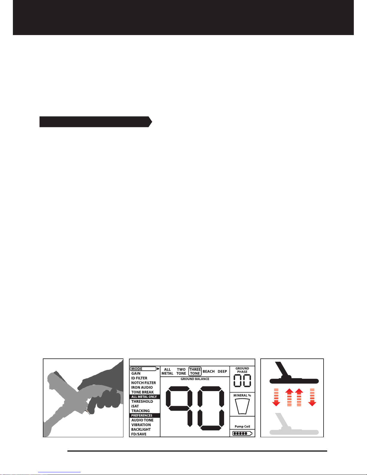
Automatic Ground Balance
Automatic ground balance is performed as follows in all search modes:
1. Find a spot where there is no metal.
2. Push the ground balance trigger forward (GROUND BALANCE value and “Pump the Coil”
warning message is shown on the display) and start pumping the search coil up and down
from about 15-20 cm (~6''- 8'') above the ground down to 3 cm (~1'') off the ground with
smooth movements and keeping it parallel to the ground.
3. Continue until a beep, indicating the completion of ground balance, is heard. Based on
ground conditions, it usually takes about 2-4 pumps for the ground balance to be
completed.
4. Upon completion of the ground balance, ground balance value is shown on the display.
The device continues to ground balance and produce a beep sound as long as you keep
the trigger pushed forward and pump the coil. In order to ensure that the ground balance
is proper, ground balance at least 2-3 times and check the ground balance values on the
display. In general, the difference between the values shall not be higher than 1-2
numbers.
5. If you cannot ground balance, in other words, if no beep sound is produced, it means
that either the ground is too conductive or not mineralized or there is a target right below
the search coil. In such a case, retry ground balance at a different spot. Perform manual
ground balance if it still fails.
When the ground balance trigger is released, the device continues to operate in the All
Metal mode for a short period of time and ground balance value stays on the display. This
makes it possible to manually fine tune the automatic ground balance value. Refer to the
following Manual Ground Balance section for further information regarding this feature. If
this is not desired, pull and release the trigger once to return to the main screen.

Page 16
Ground Balance
Manual Ground Balance
Allows you to manually modify the ground balance value. It is not preferred mostly
because it takes time. However, it is the preferred option in cases where a successful
ground balance cannot be performed using other methods or minor corrections are
required to the automatic balance.
RACER 2 is designed to allow for automatic ground balancing conveniently on any type of
ground. Therefore, it is recommended to perform automatic ground balance upon start up.
However, the ground may not be suitable for automatic ground balancing in some cases
and the device cannot ground balance on such grounds (Except for the beach mode). For
instance, wet beach sand, soils containing alkali or salty water, lands with high waste metal
content, ploughed fields, high mineralized grounds and grounds with very low
mineralization are not suitable for automatic ground balance. We recommend manual
ground balancing for making it easier to search in such areas. Manual ground balance
requires a skill which develops over time through practice.
For performing manual ground balance:
1. Find a spot without metals and switch the device to the All Metal mode.
2. You need to listen to the sounds coming from the ground in order to perform manual
ground balance. Pump the search coil up and down from about 15-20 cm (~6''- 8'') above
the ground down to 3 cm (~1'') off the ground with smooth movements and keeping it
parallel to the ground.
If the sound gets higher when lifting off the search coil above the ground, the ground
balance value is too low, in other words, the effect from the ground is negative and the
ground balance value needs to be increased by using the ( + ) button. On the other hand,
if the sound gets higher when lowering the search coil to the ground, the ground balance
value is too high, in other words, the effect from the ground is positive and the ground
balance value needs to decreased by using the ( - ) button.
3. Push the ground balance trigger forward once and release it. The ground balance value
will be shown on the display and remain there for a moment. You can return to the ground
balance screen by pushing the ground balance trigger forward if the screen switches.
4. Repeat the above procedure until the sound heard from the ground is eliminated.
The sound may not be eliminated completely in some areas. In these cases, listen to the
sounds produced when moving the search coil towards and away from the ground to
check if the ground balance is correct. If there is no difference between the two sounds
then the ground balance is set properly.
Manual ground balance functions within the range of
0-99. However, each value covers 5 steps used for fine
tuning within itself and these steps are indicated as
multiples of 20 in the Ground Phase indicator shown on
the display. For example, ground balance value shown
on the side is 70.80.
Press ( + ) and ( - ) to increase and decrease the ground
balance value, respectively. If the key is pressed once at
a time, the values count one by one and if kept pressed down, they change quickly.

Page 17
Ground Balance
The device will return to the main screen automatically after a moment upon completion
of ground balance. To return immediately, just pull and release the trigger once.
IMPORTANT! Experienced detectorists adjust the ground balance setting to little positive
response (weak but audible sound is produced when moving the search coil closer to
ground). This method may produce favorable results for experienced users in certain fields
where small targets are searched for.
TRACKING
In this option, the user does not need to make any adjustments. TRACKING feature is
activated from the menu by switching it to 01 position. The word ''Tracking'' is displayed in
the GROUND PHASE box at the upper right corner of the screen. The device updates the
ground balance automatically as long as the search coil is swung over the ground and
shows the ground balance value in the GROUND PHASE window. It does not provide any
feedback to the user (like ground balance value or a beep sound in automatic ground
balance).
While TRACKING is active, the device can initially produce a loud signal when it detects a
different ground structure (for instance a mineral rock) or a target. In this case, swing the
search coil over the spot where the device produces the signal. If the sound remains the
same and the device shows an ID, it is possibly a target. If the sound attenuates too much
or is lost after a few swings, it means that the device has produced a signal for the different
ground structure or a stone.
It is recommended that you use TRACKING in the All Metal mode and not in the
discrimination modes (Two Tone, Three Tone, Beach and Deep) for the best performance.
TRACKING is suitable for use in areas where different soil structures are present within the
same land or in fields where mineral rocks are scattered widely apart. If you use Ground
Tracking in areas where hot rocks are intensely present, the device may not be able to
eliminate these high mineralized rocks or you may miss the smaller or deeper metals.
IMPORTANT! Ensure that TRACKING is off during air tests. Otherwise, the device attempts
to perform ground balance on the target and the depth is reduced.
Ground Balance Value
Ground balance value provides information about the ground you are searching on. Some
typical ground types are as follows:
0-25 Wet salt water or wet alkali soils
25-50 Wet salt water and wet alkali soils covered with dry layers
50-70 Regular, low-quality soils
70-90 Highly magnetic soils, magnetite or maghemite and similar highly mineralized
soils, black sand
Table of contents
Other Nokta MAKRO Metal Detector manuals

Nokta MAKRO
Nokta MAKRO GOLD FINDER User manual

Nokta MAKRO
Nokta MAKRO Midi Hoard User manual

Nokta MAKRO
Nokta MAKRO Gold Finder 2000 User manual

Nokta MAKRO
Nokta MAKRO Mini Hoard User manual

Nokta MAKRO
Nokta MAKRO Simplex+ User manual

Nokta MAKRO
Nokta MAKRO PulseDive User manual

Nokta MAKRO
Nokta MAKRO PulseDive User manual

Nokta MAKRO
Nokta MAKRO The LEGEND User manual
Popular Metal Detector manuals by other brands


Whites
Whites TDI BeachHunter owner's manual

Whites
Whites Surf P.I. Pro instruction manual

Whites
Whites The Classic ID user guide

Whites
Whites Coinmaster 3 TR-AM operating instructions

National Geographic
National Geographic Junior Instructions & Learning Guide

Apollo
Apollo 2 Assembly and operating instructions


