DRAFT
NOT FOR PUBLIC RELEASE
i
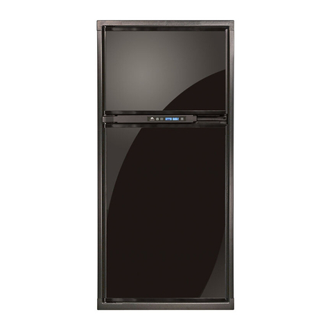
N500/N510 Models
Refrigerator Service Manual www.norcold.com/cda
TABLE OF CONTENTS
Introduction ------------------------------------------------------ 1
About this Manual................................................................. 1
Model Identification .............................................................. 1
Information Label ................................................................. 1
Cooling Unit Serial Number ................................................ 1
Certification and Code Requirements ................................ 1
About Installation ................................................................. 1
Replacement Parts.............................................................. 1
Technical Assistance ........................................................... 1
Safety Awareness---------------------------------------------- 3
Safety Notice......................................................................... 3
Attention Statements ............................................................ 3
Safety Statements ................................................................ 3
Specifications --------------------------------------------------- 4
N500 Models ........................................................................ 4
N510 Models ........................................................................ 5
Troubleshooting - Quick Reference Guide ------------ 6
N510 Displayed Fault Codes-------------------------------- 7
Troubleshooting Flowcharts - N500 Units -------------- 8
Burner Will Not Maintain Flame - N500 Units..................... 8
No AC Operation - N500 Units ............................................ 9
No DC Operation - N500.3 (3-Way Units Only).................10
No LP Operation - N500 Units .......................................... 11
Thermocouple and Interrupter Malfunctioning..................12
Troubleshooting Flowchart - N510 Units--------------- 13
Blank Display - Refrigerator does not turn on - N510 ......13
Optical Display Does Not Turn On - Power is available...14
F Fault Code - Burner failed to ignite or reignite - N510...15
E Fault Code - DC voltage high - N510 .............................16
C Fault Code - DC voltage low - N510 ..............................16
S Fault Code - Flame sense circuit failure - N510 ...........17
A Fault Code - No ac power available - N510 ...................17
H Fault Code - AC heater failed open - N510 ...................18
r Fault Code - AC relay stuck closed - N510 .....................18
Backup Operating System - N510 Models ........................ 19
Thermistor Failure Fault - Controls in Backup Operating
System Mode - N510 .........................................................19
Power Board Resetting Procedure ................................... 20
N Fault Code - No cooling detected by the controls .........20
Ventilation------------------------------------------------------- 21
Roof Exhaust Venting ......................................................... 21
Air Intake Vent .................................................................. 21
Roof Exhaust Vent............................................................21
Baffles ...............................................................................21
Vertical Angled Baffles ......................................................21
Double Sidewall Venting....................................................22
Air Intake Vent .................................................................. 22
Sidewall Exhaust Vent ......................................................22
Components ......................................................................23
Manual Shutoff Valve ....................................................... 23
Orifice................................................................................23
LP Gas System - N500 --------------------------------------- 23
Gas Safety Valve ..............................................................24
Gas Safety Valve Replacement.......................................24
LP Gas System - N510 --------------------------------------- 25
Components ......................................................................25
Solenoid Gas Valve .........................................................25
Orifice................................................................................25
LP Gas System - ALL MODELS ---------------------------26
Components Continued - All Models ................................ 26
Burner ...............................................................................26
Flue Tube..........................................................................26
Flue Cap ...........................................................................26
Flue Baffle......................................................................... 26
Handling of LP Gas Lines and Fittings .............................26
LP Gas Pressure ...............................................................27
Testing for Gas Leakage ...................................................27
Method A: .......................................................................... 27
Method B: .......................................................................... 27
Bubble leak test solution/soap and water leak test:....... 27
Pressure drop test: ...........................................................27
Burner Cleaning Procedure............................................... 28
Electrical Requirements and Components ----------- 29
AC Heater ......................................................................... 29
AC Fuse ............................................................................ 29
AC Power............................................................................ 29
AC Power Requirements - All Models .............................29
DC Power ...........................................................................29
DC Power Requirements ................................................. 29
N500 (2-way models)....................................................... 29
N510 (2-way models)....................................................... 29
N500.3/N510.3 (3-way models).......................................29
DC Heater - N500.3/N510.3.............................................29
Relighter - N500/N500.3 .................................................. 29
DC Heater–3-Way Refrigerators Only .............................30
2-Way Model Wiring .........................................................30
3-Way Model Wiring .........................................................30
DC Heater Circuit Fuse .................................................... 30
Replacing AC or DC Heater ............................................... 30
AC Power Cord................................................................... 31
N500 AC Power Cord....................................................... 31
N510 AC Power Cord....................................................... 31
N500 Terminal Block .........................................................31
AC/DC Converter as Power Source - ................................31
N510 Only ...........................................................................31
Cooling Unit----------------------------------------------------- 32
Description .........................................................................32
Heat Absorption ...............................................................32
Leveled Operation............................................................32
Gradual Decrease in Cooling Efficiency ...........................32
Cooling Monitoring - N510 Units Only............................... 32
Second "n" Fault Code .....................................................33
Cooling Monitoring Control Operation.............................33
First "n" Fault Code...........................................................33
Refrigerant Leakage - All Models ......................................33
Disposal of Cooling Unit - All Models................................33
Cooling System Diagnostic Flowchart ..............................34
Removing the Refrigerator from the Enclosure ..............36
Replacing the Cooling Unit................................................36
Removal of Cooling Unit.................................................. 37
Installation of Replacement Cooling Unit. ...................... 39
Installation of Refrigerator into Enclosure.......................40
Electronic Components - All Models-------------------- 41
Spark/sense Electrode - All Models...................................41
Replacing Spark/sense Electrode................................... 41
Electronic Components - N500 Models-----------------42
Relighter - N500 Models.................................................... 43
Replacing Relighter ......................................................... 43
Flame Indicator - N500 Models .........................................43
Flame Indicator Replacement .........................................43
Electronic Components - N510 Models-----------------43
Power Board - N510 Models .............................................43
Removal–Power Board.................................................... 43
Installation–Power Board.................................................43
Controls-----------------------------------------------------------44
N500 Controls ....................................................................44
Replacing Selector Switch - N500 ...................................45
N510 Controls ....................................................................46


