Nordco Trailblazer BC60 User manual
Model BC60 RB-UG
"Trailblazer" On-Track Brushcutter
Operation and
Maintenance
Manual
Applies to S/N 820200 and Above
Reorder Part: 49458202
Last Revision: Rev. -
OCT 2012
Read and fully understand the precautions contained in this manual before operating
or servicing this machine. Refer to Section 1 for important safety information.
Component Troubleshooting can now be found on the colored pages behind each tab.


This manual is a guide for the operation and routine maintenance of a NORDCO Railroad Maintenance
Machine. It covers product technical information, basic operating and maintenance procedures, and
safety information and is provided for use by the qualified personnel who will supervise, operate or service
the equipment described herein.
Measurements in this manual are given in both metric and customary U.S. unit equivalents.
Personnel responsible for the operation and maintenance of this equipment should thoroughly study the
manual before commencing operation or maintenance procedures.
This manual should be considered a permanent part of your machine and should
remain with the machine at all times.
Additional copies of this manual are available either as a part (Operation Manual
only) or a whole (operation and parts manual), at a nominal cost, through our Part
Sales Department. Additional service information, parts, and application information
is available through these Nordco product support resources:
NORDCO Sales: Oak Creek, Wisconsin
(414) 766-2180
sales@nordco.com
NORDCO Parts: Oak Creek, Wisconsin
1-800-647-1724
parts@nordco.com
NORDCO Service: 1-800-445-9258
service@nordco.com
We ask that if you have any comments or suggestions about this manual, let us hear from you. We are
here to be of service to you, our customers. Direct your comments and inquiries to:
Technical Documentation Department
NORDCO Inc.
245 W. Forest Hill Avenue
Oak Creek, WI 53154

HAZARDOUS MATERIAL DATA
In an effort to provide information necessary for your employee safety training program and to meet the
requirements of OSHA Hazard Communication Standard 1910.1200, we have OSHA Form 20 Safety Data
Sheets available that cover the material contained in this machine.
If you are interested in receiving this information, please refer to the Name, model, and Serial Number of
your machine when calling or writing, and direct your inquiries to:
Vice-President of Operations
NORDCO Inc.
245 W. Forest Hill Avenue
Oak Creek, WI 53154
Fax: (414) 766-2299
Phone: (414) 766-2249

BC 60 "Trailblazer" Brushcutter CONTENTS
OCT/2012 (49458202) Contents - i
SECTION 1 – SAFETY AND GENERAL INFO
Understanding Key Safety Alert Words............................................................................................ 1-1
Follow Safety Instructions ................................................................................................................ 1-1
General Safety Tips..........................................................................................................................1-2
Safety Prior to Working ...............................................................................................................1-2
Safety While Starting the Machine..............................................................................................1-3
Safety While Operating/Traveling ............................................................................................... 1-3
Safety While Parked....................................................................................................................1-3
Safety During Maintenance.........................................................................................................1-3
Safety Alerts..................................................................................................................................... 1-5
Lockout/Tagout Requirements.........................................................................................................1-6
Lockout/Tagout Procedures........................................................................................................1-6
GENERAL INFORMATION..............................................................................................................1-7
Machine Specifications................................................................................................................1-8
SECTION 2 – PRE-OPERATION, SETUP AND OPERATION
Before Operation – Getting to Know the Machine............................................................................2-1
Operator’s Station .......................................................................................................................2-1
Stick Boom Components.............................................................................................................2-1
Boom Breakaway........................................................................................................................ 2-1
Cutterhead - Saw Blade Type .....................................................................................................2-2
Engine.........................................................................................................................................2-2
Hydraulic and Electrical System..................................................................................................2-2
Controls............................................................................................................................................2-3
Engine/Pump Controls and Gauges......................................................................................... 2-3
Engine Diagnostic Gauge (Refer to Engine Manual for Diagnostic Codes).............................2-4
Travel Controls......................................................................................................................... 2-6
Cutterhead Controls.................................................................................................................2-8
Lights and Horns......................................................................................................................2-9
Misc. Controls ........................................................................................................................ 2-10
Left Valve Bank......................................................................................................................2-11
Right Valve Bank....................................................................................................................2-12
Remote Controls and Indicators ............................................................................................2-13
Workhead Lockups - Removal...............................................................................................2-14
Workhead Lockups - Installation............................................................................................2-16
Turntable Lockups ................................................................................................................. 2-18
Machine Startup............................................................................................................................. 2-19
Startup Checks.......................................................................................................................2-20
Machine Warmup Procedure.................................................................................................2-21
Travel..................................................................................................................................... 2-21
Braking...................................................................................................................................2-22
Parking/Emergency Brakes ................................................................................................... 2-22
Machine Setup ...............................................................................................................................2-23
Cutterhead Rotation (Configuration #2 is Standard)..............................................................2-23
Brake Adjustment...................................................................................................................2-23
Machine Operation
General Techniques and suggestions ...................................................................................2-24
General Operation.................................................................................................................. 2-25
After Operation...............................................................................................................................2-26
Machine Shutdown.................................................................................................................2-26
Parking Machine ....................................................................................................................2-26
Rotating machine...................................................................................................................2-26
Towing....................................................................................................................................2-26
- Continued on other Side -

GENERAL BC 60 "Trailblazer" Brushcutter
Contents - ii OCT/2012 (49458202)
SECTION 3 – MAINTENANCE
Requesting Assistance.....................................................................................................................3-1
Lubrication and maintenance........................................................................................................... 3-1
OEM Maintenance Specifications ....................................................................................................3-2
Lubrication and Maintenance Chart .................................................................................................3-3
Detailed Instructions.........................................................................................................................3-5
Cutterhead Check ....................................................................................................................3-5
Brake Adjustments...................................................................................................................3-5
Transmission level ...................................................................................................................3-6
Pump Drice ..............................................................................................................................3-7
Rope Inspection .......................................................................................................................3-8
Sheave Inspection....................................................................................................................3-9
Turbo 2000 Air .......................................................................................................................3-10
Oil Cooler ............................................................................................................................... 3-11
Drive Shafts............................................................................................................................3-12
Engine Oil Level.....................................................................................................................3-12
Hydraulic Oil...........................................................................................................................3-13
Rail Sweeps ...........................................................................................................................3-13
Suction Strainer...................................................................................................................... 3-14
Charge Pump Pressure Filter Element ..................................................................................3-14
SECTION 4 – TROUBLESHOOTING
General.............................................................................................................................................4-1
Electrical...........................................................................................................................................4-2
Mechanical.......................................................................................................................................4-6

BC 60 "Trailblazer" Brushcutter SAFETY
OCT/2012 (49458202) Section 1-1
SAFETY
Please read and comply with all of the
safety precautions in this manual BEFORE
operating this machine.
GENERAL
DO NOT use this machine for machine
operations other than for which it was
intended.
NORDCO is not responsible for any
modifications made without authorization or
written approval. Replace all NORDCO
and OEM parts with genuine NORDCO or
OEM parts. Use of non-OEM parts could
compromise the safety of your machine.
FRA regulations require that a copy of this
Operation Manual be kept on the machine
at all times. Additional copies of the
Operation Manual only can be ordered
from Nordco Parts Sales at 1-800-647-
1724.
FOLLOW SAFETY INSTRUCTIONS
Carefully read all safety messages in this
manual. Learn how to operate the
machine and how to use controls properly.
Do not let anyone operate this machine
without instruction. Failure to understand
the contents of this manual could result in
serious personal injury or death.
SAFETY ALERT SYMBOLS!
These are the safety-alert symbols.
These symbols means pay
attention! Your safety is at risk!
DANGER is used to indicate a definite
hazardous situation which, if not avoided,
WILL result in severe bodily harm or even
death.
WARNING indicates a potentially
hazardous situation which, if not avoided,
COULD result in severe bodily harm or
even death.
CAUTION indicates a potentially
hazardous situation which, if not avoided,
MAY result in minor or moderate injury.
CAUTION without the safety “!” means that
failure to follow the alert may result in
machine damage.
SAFETY means that the following points
are instructions for safely operating the
machine or the specific component of the
machine.
HAZARD DECALS ON THIS MACHINE
Hazard decals and plaques that have
been placed on this machine are to be
kept clean and legible. Replace any
decals or plaques that have become
illegible or are missing.

SAFETY BC 60 "Trailblazer" Brushcutter
Section 1-2 OCT/2012 (49458202)
GENERAL SAFETY TIPS
Only trained and authorized personnel
should be allowed to operate this machine.
In addition, all personnel at the worksite
(gang) should be aware of the safety
concerns and their individual
responsibilities prior to working this
machine.
1. Handle fuel safely. It is highly
flammable and prolonged
breathing of fumes may cause
bodily harm.
2. Prepare for emergencies. Keep a
first aid kit and fire extinguisher
handy.
3. Protect against flying pieces of
metal and debris by wearing safety
glasses or goggles.
4. Wear good-fitting pants and shirt,
no baggy or loose clothing.
5. Protect your head and eyes from
flying debris by wearing a hard hat
and safety goggles/glasses.
6. Wear leather gloves to protect your
hands from vibration or flying metal
particles.
7. Use safety-toed work boots.
SAFETY PRIOR TO WORKING
All personnel at the worksite (gang) should
be aware of the safety concerns and their
individual responsibilities prior to working
this machine:
•Review the operating instructions if
you are unsure of anything.
•Use the “pre-operational checklist”
to check the machine for obvious
faults. Repair or replace as
necessary PRIOR to operating the
machine.
•Before climbing onto the machine,
make certain the area around and
under the machine is clear of
obstructions and personnel.
•Use care when climbing onto the
machine. Always use the steps
and handrails provided. (If an area
does not have tread grips,
walkways, or other methods to
access the area, then DO NOT
attempt to access that area.)
•Make seat and control adjustments
PRIOR to starting the machine.
ALWAYS wear a seatbelt.
•Know the weather forecast and
plan your work speeds accordingly.
•There are guards on this machine.
These are to be removed ONLY
when service or maintenance is
being performed on that area of
the machine. Make certain they
have been re-installed PRIOR to
starting the machine.
•Check and service the fire
extinguisher (if so provided) at
regular intervals. Make certain all
personnel are trained in its use.
Note - Non-use of fire extinguisher
still requires that it be recharged at
the interval stated on its last
inspection notice.
•Keep the stairs, cab entry platform
and cab interior free and clear of
ice, tools and personal items. Use
the accessories provided on the
machine (tool box, cup holder, coat
hook, etc.) to properly store your
gear.
•Never climb onto the machine
while it is in motion.
•There are lockups on this machine
that are used for both work and
travel. These should be kept clear
and free of debris, grease, etc.
See Lockup section for
instructions on their use.
•Inspect safety decals and replace
when they become unreadable or
are damaged. (See “Safety
Decals”at the end of this Safety
section).

BC 60 "Trailblazer" Brushcutter SAFETY
OCT/2012 (49458202) Section 1-3
SAFETY WHILE STARTING THE
MACHINE
NORDCO recommends the use of a
Command position. This means that the
machine is never running unless someone
is at or near the main control panel. To
prevent injury to personnel or damage to
the machine, it is highly recommended to:
1. Only start and operate the machine
from the operator’s seat.
2. Use the “STARTUP Checklist” to
check the machine controls and
gauges to make certain all
systems are operating correctly.
SAFETY WHILE
OPERATING/TRAVELING
1. Never operate the machine when
people are within 800 feet of the
machine. It is also suggested that this
distance be maintained for livestock,
houses, building, cars, and highways
or other roads.
2. Never operate the machine in areas
when people may be hidden from view,
near crossings, or in double track
territory. If you must operate in double
track territory, always keep a lookout
for approaching trains and section
crews, etc.
3. Continuously be on the lookout for
hidden, immovable objects such as
rocks, boulders, concrete, etc. Contact
with such objects may cause severe
damage to the machine as well as
pose a hazard to those in the vicinity if
the cutter blades come loose and
become airborne projectiles. NOTE:
Blades or teeth could travel in excess
of 250 mph if they should come loose
from the cutter head.
4. Never allow more riders than seats and
seatbelts allow. This machine was
designed to be operated by two
people.
5. The machine is to be operated from
the Operator’s seats only. Do NOT
stand and operate this machine.
6. Press the EMERGENCY STOP
pushbutton on the center control
console in emergencies and potentially
dangerous situations.
7. If personnel or bystanders are near the
machine during operation, give a
warning signal using the air horn. If
they fail to respond to this warning,
stop operation immediately.
8. Slow down the work cycle and use
slower travel speeds in congested or
populated areas.
9. Halt work if visibility is poor. Strong
rains, fog, and extremely dusty
conditions can affect visibility in your
work area. Wait for the weather to
improve before continuing work.
10. Take extreme care when storing or
removing cutter booms from their
cradle. Avoid contact with the
machine.
11. Cutter booms MUST be stored and
locked in their cradles during travel.
SAFETY WHILE PARKED
When leaving a machine engine running,
make certain that the parking brake is
applied and the electrical interlock button
has been activated.
NEVER stop and park this machine on an
incline unless the machine wheels have
been chocked.
SAFETY DURING MAINTENANCE
The following guidelines are suggested
when performing maintenance:
1. Always chock the wheels
2. Alert others in the area that service
or maintenance is being performed
on this machine.
3. Become familiar with, and use,
your company’s lockout/tagout
procedures when performing
maintenance on this machine.
See LOCKOUT/TAGOUT
REQUIREMENTS later in this
Safety Section.
4. Do not start the engine if repairs or
work is being performed alone.

SAFETY BC 60 "Trailblazer" Brushcutter
Section 1-4 OCT/2012 (49458202)
You should always have at least
two people working together if the
engine must be run during service.
One person needs to remain in
the command position (at the
controls), ready to stop the
machine and shut off engine if the
need arises.
5. Collect oils and fuels and dispose
of them properly. There is a
danger of scalding when working
with engine oils.
6. Use only Nordco supplied repair
parts for this machine. Use of
non-OEM designed parts could
comprise the integrity of this
machine.
7. There are welding cautions on this
machine. Pay attention to them
PRIOR to welding.
8. Kits supplied by Nordco have
welding instructions included.
Welding of any components NOT
of Nordco’s manufacture or failure
to follow these instructions may
affect the stability of this machine.
9. Always wear heavy work gloves
when performing maintenance on
the cutter heads. Teeth are razor
sharp, especially when new.

BC 60 "Trailblazer" Brushcutter SAFETY
OCT/2012 (49458202) Section 1-5
MACHINE SAFETY
ALERTS
DANGER ALERTS
Improper use of this machine for
any type of operation can cause
serious injury or death.
To avoid serious injury or death,
make certain that the area around
and under the machine is clear of
all personnel and obstructions
BEFORE travelling or working.
Serious injury or death can result
from reaching into working
components while machine is
running. Make all observations
from a distance and SHUT OFF
machine while making adjustments.
Shut off engine when checking
battery electrolyte level. Do not
check or fill battery in presence of
open flame, sparks, or when
smoking. Battery fumes are
flammable and/or explosive and if
ignited will result in severe bodily
injury or death.
Do not ride on tow bar between the
machine and the towing vehicle.
Falling from a moving vehicle may
cause serious injury or death.
Do not side load booms. Using
booms in this manner may cause
the machine to derail, which will
cause severe bodily injury or death.
Always extend BOTH cuttings arms
while in superelevated areas.
Failure to do so may cause the
machine to derail, which will cause
severe bodily injury or death.
Do not operate machine within 800
feet of people, livestock, buildings,
cars, etc.
MACHINE SAFETY
ALERTS
WARNING ALERTS
Failure to engage all lockup devices
before propelling at travel speed
can result in injury to personnel
and/or extensive damage to the
machine.
Remove hoses/fittings only when
system is not pressurized. High
pressure leaks can cause personal
injury. If equipped with
accumulator, isolate using ball
valve.
Always turn off machine when
performing maintenance, making
adjustments, or whenever
unintended movement of machine
could occur; unless directed
otherwise. Failure to comply could
result in personal injury and/or
damage to the machine.
Exhaust emissions caused by the
use of the engine on this machine
may cause cancer, birth defects, or
other reproductive harm if inhaled.
Disconnect the battery before
servicing this machine. Failure to
do so could result in personal injury
from accidental engine startup.
Always wear heavy gloves when
performing maintenance on the
cutter workhead. Failure to do so
may result in severe personal
injury.

SAFETY BC 60 "Trailblazer" Brushcutter
Section 1-6 OCT/2012 (49458202)
LOCKOUT-TAGOUT PROCEDURES
NORDCO has provided the means to lockout this machine. NORDCO cannot be held
responsible for injury caused by failure to comply with your company’s Lockout/Tagout
Procedures.
The following procedures are designed to lead the operator through the steps required to shut the machine
down and prepare it for performing mechanical maintenance work. These procedures are intended to release
potentially dangerous stored energy forms and make the machine safe to begin repairs. It is your company’s
responsibility to Lockout/Tagout Procedures based on this list, train you in their proper and safe use, and to
periodically inspect your work area to verify that you are complying with the procedures. Lockout/Tagout
Procedures must be followed!
SAFETY PROCEDURES
LOCKOUT/TAGOUT
1. Apply the Electrical Interlock/Warmup.
2. Chock wheels to prevent accidental rolling of machine on grade.
3. If you have not already done so, determine which components are to
have maintenance. Place all machine mechanical systems or workheads
in the full up and locked positions.
4. When mechanical locking up of equipment is not feasible for
maintenance lower the component to the ground prior to working on the
equipment.
5. Turn the ignition switch to the OFF position. This turns off the power to
the control circuits on the machine. Place a TAGOUT card in close
proximity to the ignition switch.
6. Turn the battery disconnect switch (BDS)to the OFF position.
a. For machines with the BDS on the left side of the center (front)
control console: Place a TAGOUT card on the switch after you
have switched it to the OFF position.
b. For machines with a remotely located BDS (usually next to the
battery box itself): Close the cover to the disconnect switch and
place a LOCKOUT lock on the box after you have switched it to
the OFF position.
7. Bleed off hydraulic pressure by slowly cracking hose fitting (1/8-1/4 of
turn CCW) at the cylinder/motor/pump of the hydraulic circuit being
worked on. Service or perform maintenance on circuit after the steady
flow of oil is gone.
8. Follow all of your company’s lockout/tagout rules before proceeding.
Note: When working on machine components, be aware that moving
components during repairs may create energy (ie., moving a hydraulic
cylinder). Proper precautions should be taken.

BC 60 "Trailblazer" Brushcutter GENERAL
OCT/2012 (49458202) Section 1-7
GENERAL
This manual contains information for the BC 60 "Trailblazer" Brushcutter. Information is provided in this
manual for operation and maintenance of the machine. Information regarding operation and maintenance of OEM
parts not of NORDCO manufacture can be found at the back of this manual, behind the tab marked “Component
Data”.
Become familiar with all safety instructions, controls and instruments before operating this machine. Follow
all instructions carefully.
ABOUT THIS MANUAL
This manual has been broken down into sections which have been separated by index tabs:
Volume 1:
Mechanical has individual parts breakdown drawings and lists for each assembly
Hydraulic includes adjustment instructions and troubleshooting for the hydraulic system; and all
piping and functional drawings for a standard machine and optional equipment
Electrical, includes electrical schematics, distribution and control boxes, and cabling drawings for the
machine; as well as troubleshooting instructions
Pneumatic, includes pneumatic schematics for the machine; as well as troubleshooting instructions
Volume 2:
Component Data includes parts breakdowns and service instructions for components installed on the
machine that are not of NORDCO’s manufacture. For example, the engine and pump.
DIMENSIONAL INFORMATION
This machine exceeds AAR Plate C Clearance Diagram. Check clearance requirements
of your railroad before operating this machine.
All rights reserved. In view of the constant improvements to our equipment, the specification data and
other technical information included in this manual are subject to change. No part of this manual may be
reproduced in any form or by any means without our written permission.

GENERAL BC 60 "Trailblazer" Brushcutter
Section 1-8 OCT/2012 (49458202)
SPECIFICATIONS
GENERAL
Weight.......................................................................................................................55,800 pounds(25,310 kg)
Length ..................................................................................................................30 feet 3 inches (9.2 Meters)
Width
With Booms Retracted...................................................................................11 feet 10 inches (3.6 meters)
With Both Booms Extended........................................................................................61 Feet (18.6 meters)
Height....................................................................................................................12 feet 5 inches (3.8 meters)
Travel Speed on Rail .............................................................................................35 mph (56 km/h) maximum
Rated Draw Bar Pull (On Rail)..........................................................................................15,000 lbs. (6803 kg)
Turntable....................................................................................................Hydraulically Operated - Rail to Rail
Wheel Base .............................................................................................................................. 13 feet 6 inches
Towing Speed.................................................................35 mph (56 km/h) maximum (See towing procedure)
CAPACITIES
Fuel Tank.......................................................................................................................120 Gallons (454 liters)
Hydraulic Oil Tank.......................................................................................................... 175 gallons (662 liters)
Oil Coolers.....................................................................................................................2 @ 95,000 BTUs/hour
Boom Winch............................................................................................................................... 3 pints/1.4 liters
ENGINE
Make/Model .........................................................................................................John Deere PE6068HF485
Continuous BHP ............................................................................................................. 275 HP @ 2200 RPM
Oil Capacity........................................................................................................................................32.5 Liters
HYDRAULIC SYSTEM
Pressure Settings:
Relief Valve - Track Drive.................................................................................................5000 psi (345 bar)
Main Pump (22 GPM) Mfr...................................................................................................................................
Relief Cartridge (Valve Banks) ....................................................................................................2700 psi ( bar)
PNEUMATIC SYSTEM
Engine Mounted Compressor.................................................................................................13 cfm @ 120 psi
Unloading Valve.......................................................................................................................90 psi/110 psi
Relief Valve............................................................................................................................................. 150 psi
Tanks.........................................................................................................................................2 @ 6.5 gallons
Air Dryer................................................................................................................C/R Turbo 2000, with Heater
ELECTRICAL SYSTEM
Battery....................................................................24V dc (Two 12-Volt Batteries), 1150 Cold Cranking Amps
Ground..................................................................................................................................................Negative
Main Disconnect ................................................................................................................Negative Disconnect
DRIVE SYSTEM
Drive Type....................................................................................................................................Dual Axle Drive
Propulsion Type.........................................................................Hydraulic Motor Driven, 4-Speed Transmission
AXLE/WHEELS
Axle Size.....................................................................................................................................................5-inch
Wheel Size and Type............................................................................24 inch ( 60 cm) diameter, Forged Steel
Brake Type.................................................................................................................Cast Iron or Sintered Shoe
Items or capacities may vary according to options on your machine.
* Approximate weight. Actual weight may vary according to options on your machine. Actual weight of
your machine is as stenciled.
BC 60 "Trailblazer" Brushcutter PRE-OPERATION
DEC/2012 (49458202/8203) Section 2-1
GENERAL
DO NOT use this machine for machine
operations other than for which it was
intended.
FRA regulations require that a copy of this
Operation Manual be kept on the machine at
all times. Additional copies of the Operation
Manual only can be ordered from Nordco
Parts Sales at 1-800-647-1724.
Carefully read all safety messages in this
manual and on the decals located throughout
the machine. Learn how to operate the
machine and how to use controls properly.
Do not let anyone operate this machine
without instruction. Failure to understand the
contents of this manual could result in
serious personal injury or death.
ABOUT THIS MACHINE
It is always good practice to become familiar
with the components of the machine you are
using.
OPERATOR’S STATION
Almost all the controls for running this
machine are located in the Operator’s
Station. This includes but is not limited to,
the front machine control console, engine
controls, the propulsion controls and brake
pedals.
Under no circumstances are there to be more
riders on this machine than seatbelts
available. Always use your seat belt when
sitting in the operator seat.
For additional information concerning the
controls used in the Operator’s Station refer
to Operator Station Controls later in this
section.
STICK BOOM
The stick boom is standard on this machine.
The main boom is lifted by a motor-driven
winch operated from the cab. A secondary
(outer) boom, controlling the tilt of the
cutterhead, is positioned by a hydraulic
cylinder.
BOOM BREAKAWAY
This machine is equipped with a boom
breakaway feature. In the event that a boom
is driven into an immovable object, the boom
will automatically rotate back about 20
degrees to avoid the possibility of derailment
and/or damage to the boom assembly. The
outside valve handle on each valve bank in
front of the operator stations is a control to
reset the breakaway cylinders to their
respective working positions.
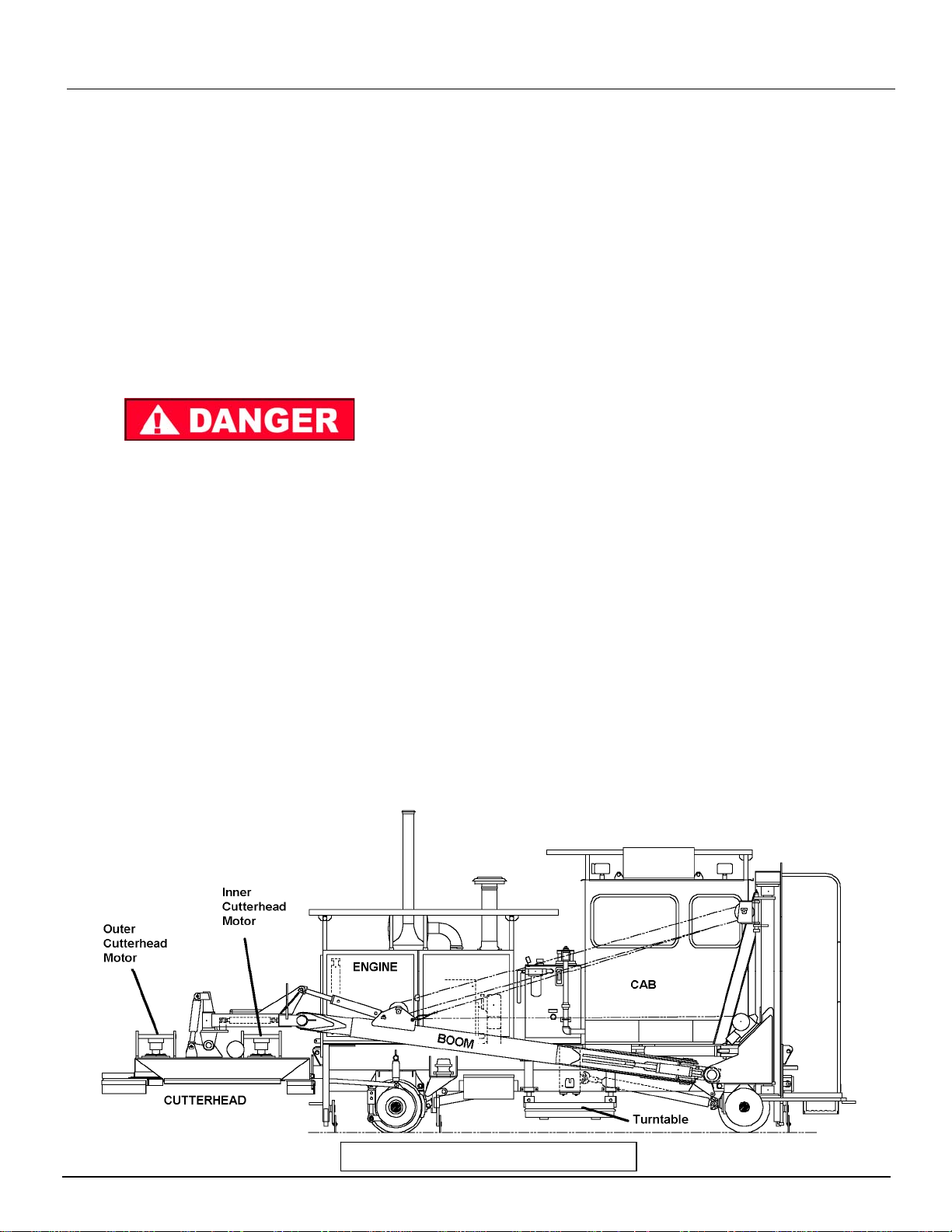
Fi
g
ure 1. Machine Overview

PRE-OPERATION BC 60 "Trailblazer" Brushcutter
Section 2-2 DEC/2012 (49458202/8203)
CUTTER HEAD – SAW-BLADE TYPE
The cutterhead consists of either a single
disk or dual disks (front and rear), each with
teeth and facebits. The Teeth are used for
cutting through dense trees and bushes. The
face bits pulverize the vegetation.
The teeth on the saw-blade type cutterhead
are razor sharp and care should be taken
when working on or in proximity to these
cutterheads.
ENGINE
Your machine is equipped with an automatic
shutdown system when low engine oil
pressure and high engine coolant
temperatures have been reached. Nefore
the machine reaches it's shutdown levels, it
will activate an audio and visual alarm.
Your machine is also equipped with a
shutdown override system, which will allow
you to override a shutdown in the event of an
emergency. This will give you time to move
the machine to a different location before
shutting down the machine and attempting to
troubleshoot the engine problems. USE
THIS SWITCH ONLY IN THE EVENT OF AN
EMERGENCY!
ELECTRICAL SYSTEM
The hydraulic functions of the machine are controlled by
the electrical system. The relays, limit switches, micro
switches and timing module that make up the electrical
system are shown on the schematics and wiring
diagrams included in the ELECTRICAL section of this
manual.
CONTROLS AND INSTRUMENTS
Some controls and all of the instruments are located on
the Main Control Panel (Logic Box). Additional controls
are located remotely on the machine. Become
thoroughly familiar with the function and operation of all
controls, as described in this section, before attempting
to operate the machine. However, the information in
this section is intended to be for descriptive purposes
only. Also read carefully the instructions in the
Operation section of this manual before attempting to
operate the machine.
NOTE:
Your machine may not have all the optional controls
and instruments that are described in this section.
Figure 2. Dual Cutter Head Overview

BC 60 "Trailblazer" Brushcutter PRE-OPERATION
DEC/2012 (49458202/8203) Section 2-3
Figure 3-1. Front Console
Engine/Pump Controls and Gauges
John Deere Engines Only
INSTRUMENT OR
CONTROL
FUNCTIONAL DESCRIPTION
FUEL GAUGE Measures the level of diesel fuel in the fuel tank. Do not allow to go into the red zone.
AIR PRESSURE
GAUGE Measures air system pressure. Normal reading is 105 to 120 psi.
SPEEDOMETER Indicates travel speed of machine in both kilometers and miles per hour.
IGNITION SWITCH The electrical system is energized by turning the switch (or optional key) to the right.
Electrical power is cut off and the engine will stop when the key is turned to the full left
or vertical (OFF) position.
When starting engine, make certain hydraulic pump switch is in the OFF position
ALARM Buzzer sounds on low air pressure, low oil pressure, and high coolant temperature.
ENGINE SPEED
SWITCH
Momentary switch used during work, travel, and shutdown. Hold switch in position until
desired engine RPM has been reached and then release switch.
PUMP SWITCH Turns pump ON or OFF. Engine will not start if the switch is in the ON position. This
is done to reduce engine load during starting.
If idling for more than 30 minutes, turn pump OFF to prevent overheating of hydraulic
oil.
SHUTDOWN
OVERRIDE SWITCH Overrides engine shutdown for EMERGENCY travel purposes.
Once pressed, engine shutdown is delayed for 30 seconds. This switch should only
be used in emergency situations where track movement is needed. Continual override
of engine may cause permanent engine damage.
For use in emergency situations only, when machine must be moved despite engine
problems. The engine is NOT protected from low oil pressure or high coolant
temperature damage in this mode.
REVERSIBLE FAN Two position switch. AUTO or OFF. Must be in the OFF position when using the
snap-on winterfront on the engine. When in the AUTO position, the fan will cycle in a
certain direction for a timed amount before switching to reverse.
MURPHY DIAGNOSTIC
DISPLAY See Next Page for more details. Refer to engine manual for error codes.
SHUTDOWN
OVERRIDE

PRE-OPERATION BC 60 "Trailblazer" Brushcutter
Section 2-4 DEC/2012 (49458202/8203)
Figure 3-2. Front Console
Engine/Pump Controls and Gauges
Cummins Engines Only
INSTRUMENT OR
CONTROL
FUNCTIONAL DESCRIPTION
FUEL GAUGE Measures the level of diesel fuel in the fuel tank. Do not allow to go into the red zone.
AIR PRESSURE
GAUGE Measures air system pressure. Normal reading is 105 to 120 psi.
SPEEDOMETER Indicates travel speed of machine in both kilometers and miles per hour.
IGNITION SWITCH The electrical system is energized by turning the switch (or optional key) to the right.
Electrical power is cut off and the engine will stop when the key is turned to the full left
or vertical (OFF) position. When starting engine, make certain hydraulic pump switch
is in the OFF position
ALARM Buzzer sounds on low air pressure, low oil pressure, and high coolant temperature.
ENGINE SPEED
Increase/Decrease
High/Bump Mode
Low
Increases or decreases engine speed when the switch to the right of it is in
HIGH/BUMP Mode.
Places engine to highest speed and enables the Increase/Decrease switch.
Places engine in low speed.
PUMP SWITCH Turns pump ON or OFF. Engine will not start if the switch is in the ON position. This
is done to reduce engine load during starting.
If idling for more than 30 minutes, turn pump OFF to prevent overheating of hydraulic
oil.
SHUTDOWN
OVERRIDE SWITCH Overrides engine shutdown for EMERGENCY travel purposes.
Once pressed, engine shutdown is delayed for 30 seconds. This switch should only
be used in emergency situations where track movement is needed. Continual override
of engine may cause permanent engine damage.
For use in emergency situations only, when machine must be moved despite engine
problems. The engine is NOT protected from low oil pressure or high coolant
temperature damage in this mode.
REVERSIBLE FAN Two position switch. AUTO or OFF. Must be in the OFF position when using the
snap-on winterfront on the engine. When in the AUTO position, the fan will cycle in a
certain direction for a timed amount before switching to reverse.
MURPHY DIAGNOSTIC
DISPLAY See Figure 3A for more details. Refer to engine tab for error codes.
SHUTDOWN
OVERRI
DE
BC 60 "Trailblazer" Brushcutter PRE-OPERATION
DEC/2012 (49458202/8203) Section 2-5
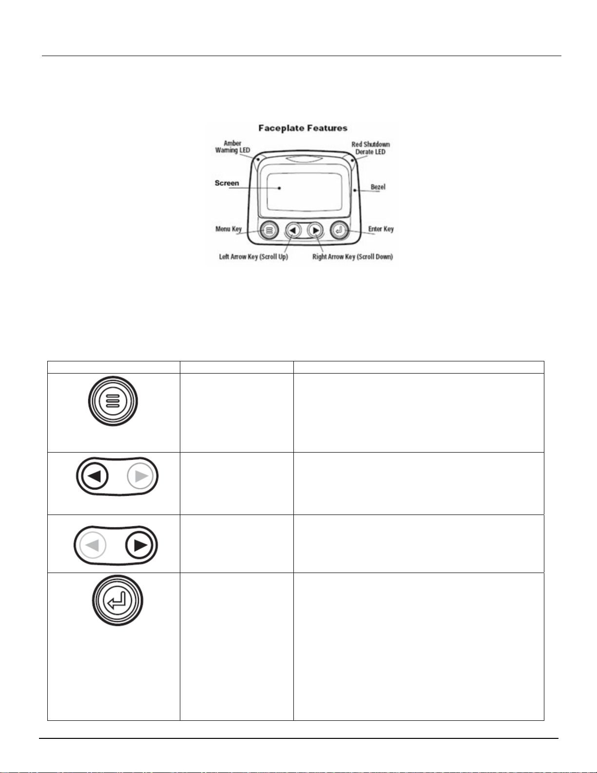
Figure 3A. Front Console
ENGINE DIAGNOSTIC GAUGE
(Upper Portion of Console)
Turn the ignition switch to the first detent (power will come on, but engine is not started) and wait.
The Powerview will come on, and a “WAIT TO START-PREHEAT” message will appear on the screen. A light (Wait
to Start) directly beneath the Powerview will turn on.
When the message disappears and the light goes out, it is safe to start the engine.
Instrument or Control Type of Control Functional Description
Menu Key The Menu Key is touched to either enter or exit the
menu screens.
The Menu key is only used during factory setup
procedures. (See Component Data Section for
additional operation and setup instructions.)
Left Arrow Use the left to move to the left or upward in a 4-Up
screen. You can use the left arrow at any time to
return to the previous screen.
Right Arrow Use the right arrow key to move to the right or
downward in a 4-Up screen, or to move to the next set
of 4 controls.
Enter Key The enter key is used when a fault occurs.
Generally, any fault that occurs will come up on the
screen at the time it happens. In order to go back
to the original status screen you have to push the
enter key once. NOTE: This will hide the fault
screen until you 1) correct the fault, or 2) you press
enter again.

PRE-OPERATION BC 60 "Trailblazer" Brushcutter
Section 2-6 DEC/2012 (49458202/8203)
Instrument or Control Type of Control Functional Description
Warning Light Amber LED
LED status lights are
located on the upper
left and upper right
sides of the powerview.
When they are lit, the
screen will tell you the
fault, the code number
for the fault, and the
method to correct the
fault.
The Amber Warning LED signals an ACTIVE FAULT
code. When the light comes on, an abnormal
condition exists. It is not necessary to shut down
the engine immediately, but problem should be
corrected as soon as possible. This light will
remain on until all faults are corrected. Note: There
may be more than one fault if <NEXT or MORE>
appears at the bottom of the screen. You can also
hide the faults by hitting the ENTER key. (Hitting
the enter key again will take you back to the fault).
NOTE: Ignoring active fault codes (warnings or
shutdown) could result in severe engine damage.
Shutdown Derate Light Red LED
LED status lights are
located on the upper
left and upper right
sides of the powerview.
When they are lit, the
screen will tell you the
fault, the code number
for the fault, and the
method to correct the
fault.
The Red Shutdown Derate LED signals a fault has
occurred that requires immediate action. Shutdown
the engine, but do not turn the switch to the off
position. You must go through the codes on the
screen and correct the problems prior to restarting
the engine. (The Powerview remembers the errors).
NOTE: Ignoring active fault codes (warnings or
shutdown) could result in severe engine damage.
Screen Display Used to monitor engine and engine controls.
HIDING FAULTS AND WARNINGS
If you have hidden (hit the ENTER key at any fault condition), and have returned to the original 4-Up (or 1-Up)
screen, the screen will now show icons in the upper right hand corner of a 1-UP screen or in the middle of the 4-UP
screen (see figure below) to show you where the faults occurred. (In the 4-up shown below, the exclamation point
appears in the middle and at the status that is showing a fault – the oil pressure.) Remember, the screen will show a
<NEXT or MORE> if more than one error has occurred.
Scroll through the screen until you find the individual component that has a fault.
Highlight the component and press the ENTER key to read the fault.
Each fault icon has a different meaning and different methods to correct. These are:
NOTE: Faults can only be cleared when the fault has been corrected.
SHUTDOWN MACHINE as soon as possible when you have encountered a
Shutdown Fault.
Table of contents


