Nordmann Engineering AT 3000 D User manual

OPERATING INSTRUCTIONS
Steam-bath Generators
2401897 EN ƔƕƓƔ
Nordmann AT 3000 D
NORDMANN
ENGINEERING
NORDMANN
ENGINEERING
Dampfluftbefeuchter econoVap
NORDMANN
ENGINEERING

2
Introduction
You have purchased a NORDMANN steam-bath generator which, provided
you observe the operating instructions, will ensure ully automatic opera-
tion and reliable, low-maintenance service. There ore, read these operating
instructions care ully and pay particular attention to the sa ety instructions
and warnings.
Should you have any queries that go beyond the scope o these operating
instructions, please contact the company rom which you purchased the
steam-bath generator. As the manu acturers, we are, o course, always
ready to be o assistance, since we want all o our customers to be com-
pletely satis ied with our products.
List of contents
1. Installation 1.1 Dimensions.............................................................................................................. 4
1.2 Fitting the steam-bath generator................................................................... 5
1.3 Laying the steam hose........................................................................................ 6
1.4 Per ume injection................................................................................................. 6
2. Water connections 2.1 Quality o the water............................................................................................ 7
2.2 Water intake and drainage................................................................................ 7
3. Electrical connections 3.1 Sa ety instructions............................................................................................... 9
3.2 Control voltage...................................................................................................... 9
3.3 Heating voltage..................................................................................................... 10
4. Putting into operation 4.1 How the steam-bath generator works.......................................................... 11
4.2 The steam cylinder and the SC-System......................................................... 12
4.3 Putting the steam-bath generator into operation.................................... 13
4.4 Automatic operation........................................................................................... 13
4.5 Programming level............................................................................................... 13
4.6 Sa ety unctions.................................................................................................... 14
4.7 In ormation rom the display........................................................................... 14
4.8 Servicing and system messages........................................................................ 16
5. Servicing and maintenance 5.1 Cleaning and replacing the steam cylinder.................................................. 17
5.2 Drainage strainer in the steam cylinder........................................................ 18
5.3 Removing the electronics unit......................................................................... 18
5.4 Taking the steam-bath generator out o operation.................................. 18
5.5 Regular servicing.................................................................................................. 18
5.6 Service program.................................................................................................... 19
6. Rectifying faults 6.1 The generator produces insu icient or no steam...................................... 22
7. Spare parts list............................................................................................................................................................................................. 22
8. List of options............................................................................................................................................................................................... 22
9. Technical specifications............................................................................................................................................................................. 23

3
Safety instructions
Please read and observe the operating instructions before fitting and
putting into operation.
Very important! The operating instructions should always be readily available and kept in
the immediate vicinity o the steam-bath generator.
All work must be done only by persons who are amiliar with the product
and are su iciently quali ied to per orm the work.
The AT 3000 D steam-bath generators have been designed and constructed
in accordance with the latest technology and the accepted sa ety
regulations. However, i misused, the steam-bath generator can present
a danger to both the user and third parties.
Apart rom these sa ety instructions, you should observe all national and
local regulations.
Proper use The AT 3000 D steam-bath generators are intended solely or indirect (via
a steam-distribution pipe in a ventilation duct) or direct (with either
a separate or a steam-bath generator-mounted an) humidi ication. Used in
any other way, or in a way that goes above and beyond the one described
above, is contrary to its intended usage. The manu acturer/supplier cannot
be held responsible or any damage resulting there rom. The user shall
bear the risk.
Alterations to the steam-bath generator Without NORDMANN’s written approval, no alterations may be made to
the steam-bath generator itsel , the components or the accessories.
The use o non-original spare parts may lead to our re usal to accept res-
ponsibility or any damage arising there rom.
Safety instructions Whenever you see either o these signs, particular care must be taken.

1.1 Dimensions
Dimensions of the AT 3000 D steam-bath generators
A
B
Befestigungsbohrungen
bei Geräte ab 15kg
Type Fig. mm mm mm Steam outlet Drainage Empty eight Full eight
ABC kgkg
41 390 585 230 1 x Ø 22 1 x Ø 22 11 14,5
81 390 585 230 1 x Ø 22 1 x Ø 22 12 18,5
15 1 470 645 305 1 x Ø 35 1 x Ø 22 17 32,5
23 1 470 645 305 1 x Ø 35 1 x Ø 22 18 33,5
32 1 525 715 360 1 x Ø 35 1 x Ø 22 28 53,5
45 1 525 715 360 2 x Ø 35 1 x Ø 22 29 54,5
4
BreiteTiefe
Höhe
1. Installation
Fig. 1
4 holes required
or steam-bath
generators o
15 kg and above
3 holes required
or steam-bath
generators
o 4 and 8 kg/h
Type A B
(mm) (mm)
4 - 8 kg 100 350
15-23 kg 180 410
32-45 kg 220 450
Fig. 2
Fixing holes for type 4-45 kg/h
C A
B

5
1.2 Fitting the steam-bath generator
All installation ork must be performed by trained personnel.
The customer himself is responsible for verifying their qualifications.
When itting the steam-bath generator, use only the material supplied
with the unit and observe the various minimum distances that have been
stipulated.
To open the steam-bath generator, turn the screw, using the correct
screwdriver, in an anti-clockwise direction; the door to the water
componentry or the electrics then opens. To close, simply push back into
place (no screwing down is necessary).
Positioning the steam-bath generator Ensure that there is su icient room to per orm servicing and maintenance
work, and that the unit is easily accessible. To acilitate such work, mount
the unit at eye level.
We recommend that you it the steam-bath generator as near as possible
to the steam-bath cabin. The highest degree o e iciency is attained when
the steam-bath generator is linked to the shortest possible steam hose.
320
380
100 100 100
Fig. 3

1.3 Laying the steam hose
The steam hose should be kept as short as possible. It should not be pos-
sible to block or obstruct the steam supply lines in any way. Furthermore,
they must be protected rom outside inter erence (e.g. de ormities,
kinking etc.).
A ter the hose has been laid, it is advisable to re-check everything when
the hose is warm.
It is equally important to avoid condensation pockets in the hose. Any
curves should have as large a radius as possible.
Installation material I a hose is used or the steam line, it must be the original one supplied
by NORDMANN. I other hoses are utilized, NORDMANN cannot be held
responsible or any damage that may occur.
When laying the steam hose in pipes, cable ducts etc., you must veri y their
resistance to high temperature (min. 100 °C). All insulation material must
also be checked or its resistance to high temperature.
I the steam line installed is o copper, small radii should be avoided
wherever possible. Every bend causes an additional resistance. A steam line
o copper must have the same diameter as the hose.
I the steam lines are long with a lot o bends, water may be continuously
orced out o the steam cylinder, which impairs per ormance.
Correctly installed
1.4 Perfume injection
The per ume should be injected in a vertical steam pipe as near as possible
to the cabin. A T-piece should be used there ore.
6
Fig. 4
Per ume

2.1 Quality of the ater
NORDMANN steam-bath generators use ordinary tap water or the
production o clean steam. The electrical conductivity should be between
125 and 1250 microsiemens per cm.
The hardness o water is measured in accordance with the international
unit millimol, calcium and magnesium ions per litre (mmol/l), previously
the degree o German hardness (DH):
So t water: up to 1.3 mmol/l; up to 7°DH
Fairly hard water: 1.3 to 2.5 mmol/l; 7 to 14°DH
Hard water: 2.5 to 3.8 mmol/l; 14 to 21°DH
Very hard water: over 3.8 mmol/l; over 21°DH
Other international units: 1°DH = 1.79° (French hardness)
1°DH = 1.25° (English hardness)
1°DH = 1.05° (American hardness)
1°DH = 10 mg/l CaO
1°DH = 17.9 mg/l CaCO3(ppm)
NORDMANN’s electrode steam-bath generators allow you to use water
ranging rom so t to very hard, without the need or prior treatment.
However, or airly hard water and above, we recommend the use o
the SC-System (NORDMANN’s sel -cleaning system), since this greatly
reduces the amount o maintenance required or the cylinder.
2.2 Water intake and drainage
All installation ork must be performed by trained personnel.
The customer himself is responsible for verifying their qualifications.
Please observe local regulations concerning the connection o appliances
to the pressure and drainage systems.
The steam-bath generators are designed to operate on ordinary tap water.
I you intend using treated or de-mineralized water, consult your
NORDMANN representative be orehand.
Connecting to the cold- ater supply, ith stop cock
Where the water pressure is between 1 and 10 bar (0.1 to 1 MPa),
the unit can be connected directly to the water supply. I it is over 10 bar
(1 MPa), connection must be via a pressure-reduction valve
(set to 4–6 bar, = 0.4–0.6 MPa).
7
2. Water connections

In any case, the water eed pipes that you have laid
must be lushed thoroughly be ore connecting
them to the steam-bath generator. You should use
copper piping only.
Note that the drainage acility should provide the
possibility o per orming cleaning and maintenance.
The drainage pipe should have a decline to the
drainage system o at least 5%.
A ine ilter should be itted at the water intake
to the steam-bath generator; this prevents the rapid
build-up o impediments in the inlet ilter o the
inlet valve.
8
Fig. 5
Tap (supplied
by customer)
Drainage cup
horizontal or
vertical
Fine ilter (sup-
plied by customer)
3/4“
3/8“

3.1 Safety instructions
All ork pertaining to the electrical installation must be carried out
by qualified personnel only. The customer is responsible for verifying the
qualifications of the technicians concerned.
Be ore per orming any electrical work, all power to the steam-bath
generator must be disconnected.
Please observe local regulations concerning electrical installations.
The installation must be itted with a device which disconnects the unit
(with a contact opening o at least 3 mm) on all phases rom the mains
power supply.
NORDMANN steam-bath generators are designed to be connected
to the earth lead and are categorized as belonging to Protection class 1
or electrical equipment.
The connection details are provided in the wiring diagrams or each type
o unit. Each unit is supplied with the appropriate wiring diagram.
External fuses per phase (A):
3.2 Control voltage
The standard control voltage is 220–240 V. A use (F1) 6 A and a spare use
located in the terminals o the use holder, are incorporated in the steam-
bath generator. The electronics and the accessories have a 24 V power
supply which is protected by a use (F2) 1.6 A. A spare use is situated in
the terminals o the use holder.
N.B.: When performing cleaning and maintenance ork on the unit,
all po er to the steam-bath generator, including the control voltage,
must be disconnected.
Type 424 824 434 834 1534 2364 3264 4564
Heating voltage
380 V 16 25 10 16 25 35 50 70
Heating voltage
400 V 16 25 10 16 25 35 50 70
Heating voltage
415 V 16 25 10 16 25 35 50 70
Type 422 822 432 832 1532 2362 3262 –
Heating voltage
220 V 20 50 16 25 50 63 100 –
Heating voltage
230 V 20 50 16 25 50 63 100 –
Heating voltage
240 V 20 35 16 25 50 63 80 –
9
3. Electrical connections

Type of unit Terminals Cross-section of Cross-section of Scre terminals for
mm2heating ire mm2control cable mm2heating voltage
PG 11
PG 16
PG 16
PG 21
PG 16
PG 36
PG 21
PG 36
PG 21
PG 36
0,75
0,75
0,75
0,75
0,75
0,75
0,75
0,75
0,75
0,75
4xx
822
8xx
1532
15xx
2362
23xx
3262
32xx
45xx
4
10
4
10
6
16
10
35
10
16
2,5
4
2,5
2 x 2,5
2,5
2 x 4
2 x 2,5
2 x 4
2 x 2,5
2 x 4
3.3 Heating voltage
The cross-section o the electrical wires and the minimum use size should
be chosen in accordance with the connection requirements (c . technical
speci ications) o the type o steam-bath generator employed. The electric
supply cables must be connected to the unit’s terminals correctly.
We recommend that the screw terminals be re-tightened a ter a ew days.
10

11
4.1 Ho the steam-bath generator orks
NORDMANN steam-bath generators use ordinary tap water to produce
steam. The water is converted directly into steam in a steam cylinder by
electrode heating using electrical energy. In so doing, the water acts as
the electrical resistance. Vaporisation occurs at atmospheric pressure (non-
pressurized).
The electronic control system, with its highly-integrated microcontroller,
regulates the vaporisation process in accordance with a new principle de-
veloped by NORDMANN which allows rapid output changes to be made.
The autosensitive temperature control allows a continuous steam output.
The smallest deviations o the temperature in the cabin are levelled out
immediately. The steam-bath generator adapts itsel ully automatically to
the quality o the water used. Due to this ability to set the optimum
water concentration in the steam cylinder, the smallest o adjustments to
the water level can e ect a change in the steam output. There ore,
the unit reacts quickly and accurately to any setpoint changes. Because
o its ultimate degree o e iciency, this new type o control system
ensures per ect drainage, i.e. the process o water deconcentration in
the cylinder.
The use o uzzy logic technology improves the controllability. The micro-
controller o the AT 3000 D series works with uzzy-logic algorithms. This
regulates the conductivity or mineral concentration in the steam cylinder
and achieves ideal operating conditions while, at the same time, maximi-
sing the operational reliability. Furthermore, the output luctuations which
occur during normal operation are kept to a manageable minimum by
the automatic water-intake and drainage unctions.
S
EE
Fig. 6
Hydrodynamic
illing cup
S = maximum-level sensor
E = electrode
Drainage valve Inlet valve
4. Putting into operation

10
20
30
1000500 1500 2000
t (h)
°d Härte
4.2 The steam cylinder and the SC-System
The SC-System is a patented sel -cleaning system developed
by NORDMANN or its electrode steam-bath generators. Because the
minerals are kept in suspension, there is little accumulation o
deposits on the loor o the cylinder. The loose minerals are lushed away
during normal drainage operations. The steam cylinder’s service
li e is considerably lengthened and the time spent on maintenance is reduced.
The serviceable li e o a steam cylinder is dependent on both the quality o
the water supply and the unit’s actual operating hours.
Lifetime of a steam cylinder at 100% steam output
A regular check o the steam cylinder ensures trouble- ree operation.
I the steam-bath generator indicates U1 (see page 16), it can still be run
or a ew days be ore the steam cylinder needs to be replaced.
We recommend that you keep a spare cylinder in stock or each unit.
12
Fig. 7
1°DH = 1.25° English hardness
1°DH = 1.79° French hardness
1°DH = 1.05° American hardness
1°DH = 17.9 mg/I CaCo3(ppm)
Hours
ith SC-System
ithout*
SC-System
ºDH (German hardness)
*but cylinder is lushed periodically

13
NORDMANN’s steam cylinders are so economical that it is usually cheaper
to replace the cylinder than to clean it. To clean the cylinder, it should irst
be emptied ( =1 in the service level) and then removed. A ter the drainage
ilter has been taken out, the cylinder can be well lushed with tap water
(using no chemical substances).
4.3 Putting the steam-bath generator into operation
A ter the steam hose, water eed pipe, drainage pipes and electrical cables
have all been correctly connected, the AT 3000 D steam-bath generator
can be switched on using the black power switch. When the T1 key is
pressed, the automatic steam production begins.
As soon as the temperature sensor demands steam, the contactor is
activated and, soon a ter, water is ed into the steam cylinder, whereupon
ully automatic operation commences.
O course, the steam-bath generator will operate automatically only
i (a) it was installed by a specialist and (b) the shut-o valve in the water
eed pipe is open.
A ter the water in the steam cylinder has been heated up, the production
o steam begins.
During the start-up phase, or a ter a new replacement cylinder has been
itted, the maximum water level, or Niveau max. can be attained.
When Niveau max. has been reached, the inlet valve closes brie ly; this
is a normal occurrence during the steam cylinder’s concentration
phase. The length o this phase can di er; it lasts until the cylinder has
reached the nominal rating. In the irst stage o the service level,
you can check whether Niveau max. has been attained (see Item 5.6).
4.4 Automatic operation
The AT 3000 D series’ special electronic controls unit with microcontroller
regulates all operations automatically, so that the user does not need
to take any action or make any settings during normal running.
4.5 Programming level
The steam-bath generators o the AT 3000 D series have a programming
level which has a large array o unctions, allowing the unit’s charac-
teristics to be matched to a wide variety o conditions or tailored exactly
to the customer’s particular requirements.
You are not permitted to use the programming level unless authorisation
to do so has been granted by a NORDMANN specialist. Your NORDMANN
representative will be glad to advise you in this matter.

4.6 Safety functions
NORDMANN steam-bath generators are protected against running dry, i.e.
the power is cut o automatically as soon as the electrodes in the steam
cylinder protrude above the water level.
I current consumption becomes excessive (25% above the normal level),
the outlet valve is opened automatically. Because the electrodes are then
in contact with less water, current consumption alls back to the nominal
value.
I current consumption ails to all below 140% o the nominal level even
a ter several drainage operations, the steam-bath generator soon turns
itsel o automatically, and U2 appears in the display.
4.7 Information from the display
The large-scale, our-digit, LED display allows numbers and letters to be
indicated. Its size and clarity mean that it can be read easily even when the
light is poor.
Key Function
T1: With this key the automatic temperature-controlled steam
production is switched on or o . The red LED lights up upon
switching on and keeps dark upon switching o .
T2:
Key or the switching on or o o the cabin light. The red LED
lights up upon switching on and keeps dark upon switching
o . A lamp 24 V AC and max. 35 W can be connected on
terminals 41 and 42. The light circuit is protected by a 3.15 A
use.
T3: This key allows the switching on o the automatic per ume
injection. The red LED lights up upon switching on. At the
same time, the red LED on the key T6 (SET) lashes during 10
seconds. The dosage igure 5, set ex works, appears on the
display. It is possible to adjust this igure rom 1 to 10 with
the key SET. 1 is or very little per ume and 10 is or very
much per ume.
In case igure 0 is entered, it is then possible to individually
set the dosage interval and the dosage duration with unc-
tions 40 and 41 o the program level.
A per ume pump 230 V AC, max. 3 A, can be connected to
terminals 43 and 44.
14
Fig. 8
Dosage igure Interval (mn) Injec. duration (sec)
1102
282
363
453
5 ex works 4 3
633
724
815
916
10 1 7

15
T4: Allows you to select:
• adjustment o the temperature setpoint
• access to the programming level
• access to the servicing level
• operation o the exhaust an 230 V
The relevant LED shows which option you have selected.
1. Adjustment of the temperature setpoint
On pressing T6 (SET), the desired setpoint o the cabin can be
adjusted between 35 and 55 °C. When another key is pressed,
the value is automatically saved.
2. Activating the programming level
The activating o the programming level is generally not ne-
cessary. In special cases, the programming level enables the
generator to be matched to particular installation conditions.
There ore, please contact your NORDMANN specialist.
3. Activating the servicing level (cf. Item 5.6)
On pressing T5 (SELECT) you scroll through the unctions
o the service level. The SET key enables to obtain in ormation
or per orm the components’ check.
4. Operation of the exhaust fan
A ter the key T1 or automatic steam production has been
pressed, the exhaust an that is connected to terminals
45 and 46 is switched on automatically. Ex actory, a pre-
and post-running time o 2 and 15 minutes respectively
have been set. The key (SET) enables a manual on or o
switching o the exhaust an.
T5: The SELECT key allows you to:
• select stored unctions in the programming level
• select de ined checking stages in the servicing level
T6: The SET key allows you to:
• set the dosage igure o per ume when the automatic
per ume injection has been selected
• adjust the temperature setpoint
• activate, de-activate or parameter the special unctions in
the programming level
• switch on or o particular elements in the servicing level
Reset Key T6 (SET) also serves as a RESET button when “U codes”
appear in the display. As urther RESET procedure, the black
main switch can also be switched o and on.
Master set This operation puts all settings to the actory setting, except:
– working hours meter unctions 04, 06
– no. o program changes unction 05
– service message U5 unction 50
• Use T4 to select the programming level
• Use T5 (SELECT) to select unction 99
• Use T6 (SET) to enter the number 1
• leave the program level
Fig. 8

4.8 Servicing and system messages
The newly-developed electronic controls unit with microcontroller con-
tinuously monitors the operations o the AT 3000 D steam-bath generators.
Any deviations rom the operating condition (U codes) are shown on the
display.
Code
U 1 Servicing signal
The steam cylinder can no longer attain the nominal output and needs,
there ore, to be cleaned or perhaps replaced. A visual inspection o the
inside o the cylinder is necessary to be able to decide whether it needs
replacing. Code U1 is purely a servicing code; the unit does not switch o
automatically. The steam-bath generator continues to unction at
a reduced output. Acknowledgement is e ected by the reset procedure
(c . Item 4.7).
U 2 Excess current
Whenever there is excess current (140% o the nominal value) during
normal operations, the steam-bath generator switches itsel o
automatically or sa ety reasons. A ter the ault has been recti ied, the
steam-bath generator is put back into operation by means o the
reset procedure (c . Item 4.7).
U 3 The steam-bath generator fills continuously. Either there is no heating
phase or no water in the cylinder due to the water supply having been cut
o . The steam-bath generator switches itsel o automatically a ter
30 minutes and is put back into operation by means o the reset procedure
(c . Item 4.7).
U 4 Microcontroller uncoded
This signal appears i a replacement electronic controls unit has been itted
to the steam-bath generator without being coded. The steam-bath
generator is prevented rom operating. The signal disappears as soon as the
electronic controls unit has been coded.
U 5 Preset number of operating hours attained
This signal can appear only i the number o operating hours or the steam
cylinder has been pre-programmed. This is o bene it, or example,
i regular servicing periods have been prescribed in accordance with hours
run. U5 is purely a servicing code; acknowledgement is e ected with
unction Nr. 51 in the program level.
U 6 Temperature sensor defective
The sensor has been interrupted or short-circuited. It entails an automatic
switching o o the generator.
16

17
5.1 Cleaning and replacing the steam cylinder
Before commencing, s itch off all po er to the steam-bath generator
and disconnect the unit from the mains.
The serviceable li e o the steam cylinder depends on both the hours run
and the hardness o the tap water used.
The cylinder should be replaced when the electrodes have become insulated
so much (because o calci ication) that the required steam output can-
not be reached. At the same time, the water level in the cylinder
continuously touches the Niveau max. sensor. In this case, the specially-
constructed water illing cup o ers additional protection by eeding excess
water directly into the over low acility, allowing it simply to drain away.
Whenever U1 appears in the display, you should proceed as described on
page 16. However, the steam-bath generator can still be run or some time
be ore you need to replace the steam cylinder.
Procedure for replacing the steam cylinder
• Select service level with key T4
• Open the drainage valve in the service level ( =1); the cylinder then
empties itsel completely.
Let the cylinder cool do n.
• Be ore proceeding urther, disconnect the unit rom the mains.
• Loosen the clamp on the steam hose, pull o the hose and remove the
electrical plug rom the cylinder; the cylinder itsel can now be removed.
• To it the new unit, reverse the above procedure. It is advisable to wet
slightly either the O-ring seal on the drainer or the outside o the cylin-
der’s drainage aperture, since this makes it easier to it the new cylinder.
• Close the drainage valve in the service level ( =0).
The steam-bath generator is re-started in accordance with the recommen-
dations detailed in the chapter entitled “Putting the steam-bath generator
into operation”.
Fig. 9
black red
white
black
red
white
5. Servicing and maintenance

5.2 Drainage strainer in the steam cylinder
All NORDMANN steam cylinders are itted with a removable drainage
strainer which can be extracted easily or cleaning.
The cylinder can then be put back into place and the steam-bath generator
put back into operation.
5.3 Removing the electronics unit
All ork pertaining to the electrical installation must be carried out
by qualified personnel only. The customer is responsible for verifying the
qualifications of the technicians concerned.
Be ore removing the electronics unit, all power to the steam-bath gene-
rator must be switched o .
The electronics unit comprises a processor pcb (printed circuit board)
and a display pcb. All pcbs have plug-in connections, which acilitates their
replacement.
5.4 Taking the steam-bath generator out of operation
Should you wish to take the steam-bath generator out o operation or a
long period o time, the steam cylinder must be emptied.
Before proceeding, s itch off all po er to the steam-bath generator.
5.5 Regular servicing
Regular servicing helps to maintain the operability and reliability o the
steam-bath generator.
All ork must be carried out by qualified personnel only.
The customer is responsible for verifying the qualifications of the
technicians concerned.
Before commencing ork, all po er to the steam-bath generator must
be s itched off.
18

19
The follo ing checks should be carried out on a regular basis:
•Inspect and clean the steam cylinder.
I there are any deposits in the steam cylinder, you should remove the
drainage strainer and lush the cylinder thoroughly with tap water
(using no chemical substances). I the electrodes are worn, it is time to
replace the steam cylinder.
• Inspect the steam and ater hoses.
Check that they are still correctly laid and that the hose clamps are still
tight. Check that the hoses are still in good condition.
• Inspect and clean the inlet and outlet valves.
I worn, or covered in scale deposits, replace the valves.
• Check the drainage cup and, if necessary, clean or replace it.
5.6 Service program
The service program o the AT 3000 D steam-bath generators provides you
with in ormation on operating conditions and allows you to check the
components. You are advised to check the components on a regular basis.
The service program is or interrogation and checking only. A ter you have
le t the service program, the steam-bath generator works in accordance
with the operating conditions that were set originally.

Checking operations:
SE: Check the Niveau max. sensor
S: Check whether setpoint is higher than actual temperature
i: Indication o heating current in A
:Steam output in % o nominal capacity
- -: I you continue, steam production will be interrupted
E: Simulation o steam production demand
I: Inlet valve
:Outlet valve
C: Contactor
SC: Sel -cleaning system
r1: Relay or light
r2: Relay or per ume
r3: Relay or exhaust an
End: End o the service-program
I you choose SE,S,i, , the steam-bath generator continues to produce
steam; or all other unctions, steam production is interrupted.
You can return rom unction to unction i,Sund SE by pressing SET.
Starting the service program ☞• Key T4 Select the servicing level
☞• SELECT To select the checking operations
☞• SET To select either 1 (active) or 0 (inactive), or to switch
components on or o
Display indications SE 1: Niveau max. in the steam cylinder has been reached
SE 0: Niveau max. in the steam cylinder has not been reached
S1: Setpoint o cabin temperature is higher than actual value
S0: Setpoint o cabin temperature is lower than actual value
Part 1 i : Heating current in A
:Steam output in % o nominal
- - : I you continue, steam production will be interrupted
20
Fig. 10
Table of contents
Popular Portable Generator manuals by other brands
Restrain
Restrain B100 manual
Agilent Technologies
Agilent Technologies E4423B Installation notes
Future Automation
Future Automation SPU10 installation instructions
Generac Power Systems
Generac Power Systems GP3250 specification
Briggs & Stratton
Briggs & Stratton PowerBoss 30221 Illustrated parts list
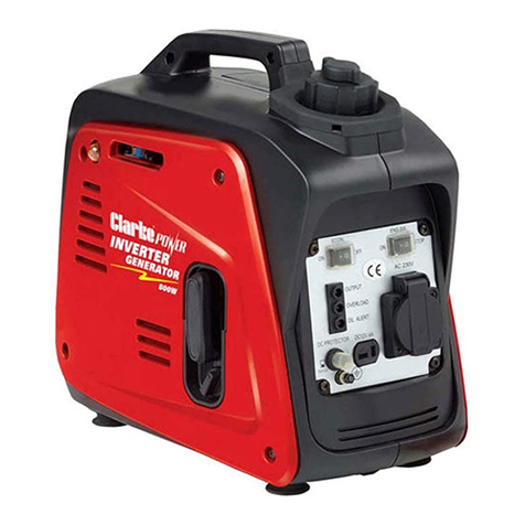
Clarke
Clarke IG950C Operation & maintenance instructions
