BE BE-12000ER User manual

User Manual
BE-12000ER
PORTABLE GAS
GENERATOR
BEPOWEREQUIPMENT
.COM

23
Introduction
4 Using the Operators Manual
Product Identification
5 Generator
5 Engine
Safety
6 Safety Rules
6 Hazard Symbols and Meanings
9 Ground Fault Circuit Interrupter Protection
11 Important Safety Instructions
Glossary
13 Glossary
Generator Components
14 12000ER Component Chart
15 Spare Parts List
17 Sockets
Features
18 Features
Operation
19 Unit Grounding
Starting the Generator
19 Filling Oil
20 Oil Specification Chart
20 Filling Fuel
21 Turn On The Fuel Valve Lever
21 Close The Choke Valve
21 Start The Generator
22 Start The Generator Recoil Start
22 Open The Choke Valve
23 Connect To Load
Stopping the Generator
23 Disconnect Load
23 Turn Off The Engine Switch
24 Close The Fuel Valve Lever
Storage
24 Drain The Fuel
24 Protective Treatment
Transporting
25 Transporting
Accessories
26 Accessory Installation
26 Two-Wheel Short Axle
Maintenance
27 Maintenance Chart
28 Replace Engine Oil
28 Clean Air Cleaner
29 Clean The Fuel Valve Lever Sediment Cup
29 Clean The Spark Plug
30 Valve Clearance
Troubleshooting
31 Troubleshooting Chart
32 Troubleshooting Analysis
Diagrams
33 Electrical Schematic Diagram 1
34 Electrical Schematic Diagram 2
TABLE OF CONTENTS TABLE OF CONTENTS

45
Using the Operator’s manual
The operating manual is an important part of your generator. It should
be read thoroughly before initial use, and referred to often to make sure
adequate safety and service concerns are being addressed.
Reading the owner’s manual thoroughly will help avoid any personal
injury or damage to your machine. By knowing how best to operate this
machine you will be better positioned to show others who may also
operate the unit.
This manual contains information for the complete range of BE
generators, and was written to take you from the safety requirements
to the operating functions of your machine. You can refer back to the
manual at any time to help troubleshoot any specific operating functions,
so store it with the machine at all times.
Attention: Read through the complete
manual prior to the initial use of your
generator.
Record Identification Numbers
Generator
If you need to contact an Authorized Dealer or Customer Service line
(1-866-850-6662) for information on servicing, always provide the
product model and identification numbers.
You will need to locate the model and serial number for the machine and
record the information in the places provided below.
Date of Purchase:
Dealer Name:
Dealer Phone:
Product Identification Numbers
Model Number:
Serial Number:
INTRODUCTION PRODUCT IDENTIFICATION

67
The safety alert symbol ( ) is used with a signal word (DANGER,
CAUTION, WARNING), a pictorial and/or a safety message to alert you
to hazards.
DANGER indicates a hazard which, if not avoided, will result in death
or serious injury.
WARNING indicates a hazard which, if not avoided, could result in
death or serious injury.
CAUTION indicates a hazard which, if not avoided, might result in
minor or moderate injury.
NOTICE indicates a situation that could result in equipment damage.
Follow safety messages to avoid or reduce the risk of injury or death.
HAZARD SYMBOLS AND MEANINGS
Save these Instructions
SAFETY RULES
This is the safety alert symbol. It is used
to alert you to potential personal injury
hazards. Obey all safety messages that
follow this symbol to avoid possible
injury or death.
explosion
kickback read manual
fire burning electric shock
toxic fumes
WARNING
Generator exhaust contains carbon monoxide, a
poisonous gas that can kill you.
You CANNOT smell or see this gas.
• Use the generator outdoors, away from open windows, vents, or
doors that could allow the carbon monoxide gas to come indoors.
Keep the generator at least 1 meter (3 feet) away from any structure
or building during use.
• NEVER use a generator indoors, including in homes, garages,
basements, crawl spaces, and other enclosed or partially-enclosed
areas, even with ventilation. Opening doors and windows or using
fans will not prevent carbon monoxide build-up in the home.
• NEVER use a generator in enclosed or partially-enclosed spaces.
Generators can produce high levels of carbon monoxide very quickly.
When you use a portable generator, remember that you cannot smell
or see carbon monoxide. Even if you can’t smell exhaust fumes, you
may still be exposed to carbon monoxide.
• NEVER operate the generator in an explosive atmosphere, near
combustible materials or where ventilation is not sufficient to carry
away exhaust fumes. Exhaust fumes can cause serious injury or death.
• If you start to feel sick, dizzy, or weak while using a generator, get
to fresh air RIGHT AWAY. DO NOT DELAY. The carbon monoxide
from generators can rapidly lead to full incapacitation and death.
• If you experience serious symptoms, get medical attention
immediately. Inform medical staff that carbon monoxide poisoning
is suspected. If you experienced symptoms while indoors, have
someone call the fire department to determine when it is safe to
re-enter the building.
SAFETY SAFETY

89
WARNING
Fuel and its vapors are extremely flammable and
explosive.
Fire or explosion can cause severe burns or death.
When Adding or Draining Fuel
• Observe all safety regulations for the safe handling of fuel. Handle
fuel in safety containers. If the container does not have a spout, use
a funnel.
• Do not overfill the fuel tank, leave room for the fuel to expand.
• Do not refill fuel tank while the engine is running. Before refueling the
generator, turn it off and let it cool down. Gasoline spilled on hot
engine parts could ignite.
• Fill the tank only on an area of bare ground. While fueling the tank,
keep heat, sparks and open flame away. Carefully clean up any spilled
fuel before starting engine.
• Always fill fuel tank in an area with plenty of ventilation to avoid
inhaling dangerous fumes.
• NEVER store fuel for your generator in the home. Gasoline, propane,
kerosene, and other flammable liquids should be stored outside of
living areas in properly-labeled, non-glass safety containers. Do not
store them near a fuel-burning appliance, such as a natural gas water
heater in a garage. If the fuel is spilled or the container is not sealed
properly, invisible vapors from the fuel can travel along the ground and
can be ignited by the appliance’s pilot light or by arcing from electric
switches in the appliance.
WARNING
The GFCI may not function unless the generator is properly
grounded. Follow the correct procedure specified in the section
labeled GROUNDING INSTRUCTIONS.
GROUND FAULT CIRCUIT INTERRUPTER PROTECTION
These generators are equipped with a GFCI (Ground Fault Circuit
Interrupters) 120V duplex receptacles for protection against the hazards
of electrical shock from defective attachments such as, tools, cords,
and cables.
A GFCI is a device that interrupts electricity from either the utility or
generator by means of a special type of circuit breaker that determines if
a current flow to the ground occurs.
A GFCI can be used only with generators that have the neutral wire
internally bonded to the frame, and the frame properly grounded to the
earth. A GFCI will not work on generators that do not have the neutral
wire bonded to the frame, or on generators which have not been properly
grounded. All BE generators have internally bonded ground wires.
SAFETY SAFETY
WARNING: This product can expose you to
chemicals including lead, which is known to the
State of California to cause cancer and birth
defects or other reproductive harm. For more
information, go to www.P65Warnings.ca.gov.
Wash hands after handling.
THERE IS A PERMANENT CONDUCTOR BETWEEN THE
GENERATOR (STATOR WINDING) AND THE FRAME.

10 11
DANGER
Improper grounding can result in a risk of electrocu-
tion. Check with a qualified electrician for your local
requirements if you are in doubt as to whether the unit
is properly grounded.
This generator is equipped with a grounding terminal for added
protection. Using the ground path from the generator to an
external ground source as instructed in the section labeled “Grounding
Instructions” in the Preparation section of this manual can be
necessary. Please consult a qualified electrician for local regulations.
The generator is a potential source of electrical shock if not kept dry.
Keep the generator dry and do not use in rain or wet conditions. To
protect from moisture, operate it on a dry surface under an open,
canopy-like structure. Dry your hands if wet before touching the
generator.
Plug appliances directly into the generator. Or, use a heavy duty,
outdoor-rated extension cord that is rated (in watts or amps) at least
equal to the sum of the connected appliance loads. Check that the
entire cord is free of cuts or tears and that the plug has all three
prongs,especially a grounding pin.
NEVER try to power the house wiring by plugging the generator into
a wall outlet, a practice known as “back feeding”. This is an extremely
dangerous practice that presents an electrocution risk to utility workers
and neighbors served by the same utility transformer. It also bypasses
some of the built-in household circuit protection devices.
If you must connect the generator to the house wiring to power
appliances, have a qualified electrician install the appropriate
equipment in accordance with local electrical codes.
This product has been designed with internal grounding or floating
bonded neutral. If it should malfunction or breakdown, grounding pro-
vides a path of least resistance for electric current to reduce the risk of
electric shock.
• Do not enclose the generator or cover it. The generator may become
overheated if it is enclosed. If generator has been covered to protect if
from the weather during non use, be sure to remove it and keep it well
away from the area during generator use.
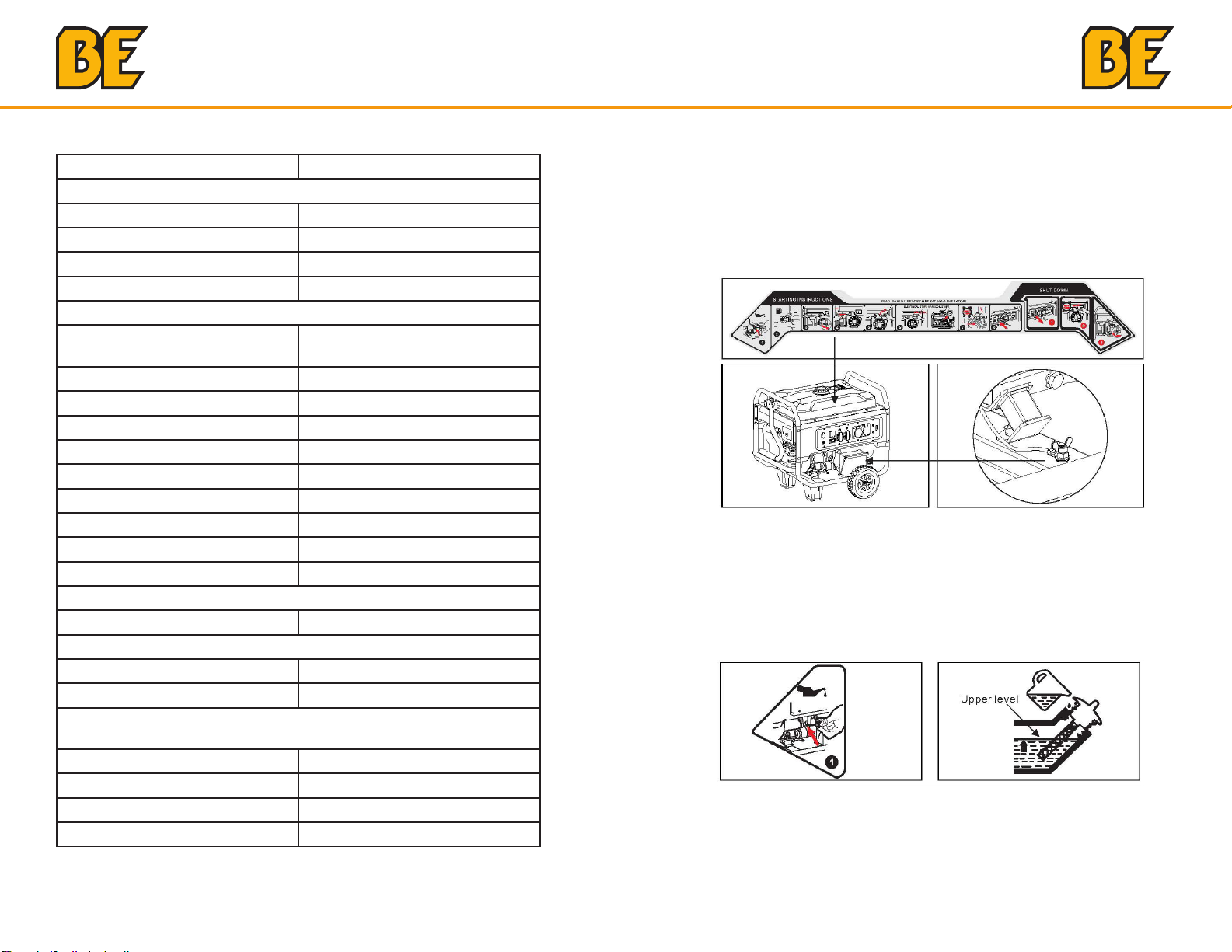
• Operate the generator on a level surface. It is not necessary to prepare
a special foundation for the generator. However, the generator will
vibrate on an irregular surface, so choose a level place.
If the generator is tilted or moved during operation, fuel may spill and/or
the generator may tip over, causing a hazardous situation.
Proper lubrication cannot be expected if the generator is operated on a
steep incline or slope. In such a case, piston seizure may occur even if
the oil is above the upper level.
• Pay attention to the wiring or extension cords from the generator to the
connected device. If the wire is under the generator or in contact with
vibrating part, it may break and possibly cause a fire, generator burnout,
or electric shock hazard. Replace damaged or worn cords immediately.
• Do not operate in rain, in wet or damp conditions, or with wet hands.
The operator may suffer severe electric shock if the generator is wet due
to rain or snow. If wet, wipe and dry it well before starting. Do not pour
water directly over the generator, nor wash it with water.
• Be extremely careful that all necessary electrical grounding procedures
are followed during each and every use. Failure to do so can be fatal.
• DO NOT smoke while charging a battery. The battery emits flammable
hydrogen gas, which can explode if exposed to electric arcing or open
flame. Keep the area well ventilated and keep open flames / sparks away
when charging a battery.
• The engine becomes extremely hot during and for some time after
operation. Keep combustible materials well away from generator area.
Be very careful not to touch any parts of the hot engine especially the
muffler area or serious burns may result.
IMPORTANT SAFETY INSTRUCTIONS
WARNING
To reduce the risk of injury, read this operator’s manual
completely before using.
When using this product, the following basic
precautions should always be followed.
SAFETY SAFETY

12 13
• Keep children and all bystanders at a safe distance from work area.
• It is absolutely essential that you know the safe and proper use of the
power tool or appliance that you intend to use. All operators must read,
understand and follow the tool / appliance owners manual. Tool and
appliance applications and limitations must be understood. Follow all
directions given on labels and warnings. Keep all instruction manuals
and literature in a safe place for future reference.
• Use only “LISTED” extension cords. When a tool or appliance is used
outdoors, use only extension cords marked “For Outdoor Use”.
Extension cords, when not in use should be stored in a dry and well
ventilated area.
• Always switch off generator’s AC circuit breaker and disconnect tools
or appliances when not in use, before servicing, adjusting, or installing
accessories and attachments.
• Make sure the engine is stopped before starting any maintenance,
servicing or repair.
NOTE: Make sure maintenance and repair of the generator are performed
by properly trained personnel only.
SAVE THESE INSTRUCTIONS
Glossary
SYMBOL NAME MEANING
VVolt Voltage
AAmpere Current
HzHertz Frequency (1Hz=60 r/min)
WWatt Power
RPM Revolutions per Minute Engine Speed
PF Power Factor Load transfer efficiency
G1 Performance Rate Generator output power perfor-
mance rate meat ISO8528G1
Following symbols are quoted on the machine or in this manual. Please
understand their meaning, which will make your operation easier and
safer.
SAFETY GLOSSARY

14 15
Read this operator’s manual and safety
rules before operating your generator.
BE-12000ER 12000watt
1) Fuel Gauge
2) Chock Valve
3) Fuel Valve Lever
4) Air Cleaner
5) Engine Switch
6) Handrail Pipe
7) Starter Grip
8) Foot
9) Oil Drain Bolt
10) Wheel
11) Oil Filler Cap
12) Ground Terminal
13) Battery
14) Timer
15) DC Output
16) AC Output
17) AC Circuit Breaker
18) Panel Seat
19) Voltmeter
20) Fuel Tank Cap
21) Fuel Tank
22) Cover, Generator End
23) Muffler
24) Cylinder Head
25) Carburetor
26) Spark Plug
SPARE PARTS LIST
Fuel Tank It is used to hold fuel, gasoline is allowed only.
Fuel Tank Cap Screw the fuel injection port in use and do not
open it in equipment operation.
Fuel Gauge It is to indicate fuel level in the fuel tank.
AC Output
AC output socket provides the power supply.
Please refer to models parameter table for its
rated power. Load of each socket cannot exceed
its rated current and total power of electric device
cannot surpass rated power of the generator. Do
not start up several electric devices simultaneously,
but switch on another one after stable operation of
one electric device.
AC Circuit
Breaker
It will break to protect the electric device when
current is too heavy.
Output Indicator It is to indicate power supply status. The indicate
will brighten up when the equipment operation.
DC Output
The output DC is 12V with maximum of 8.3A. It
is only used for automotive battery charging with
rated 12V. Pay attention to connecting the positive
and negative electrode correctly.
Engine Switch
It is to start up (applicable to electrical starting
only) and switch off the engine. Turn to the off
state in non use.
Wheel (optional) It is for moving the generator in a short time.
Battery It is for starting up the generator. In case of non
use for three months, charge it.
Oil Filler Cap
It is for measurement of engine’s oil level. Make
sure engine’s oil level is between MIN and MAX in
the dipstick of oil filler cap before use. Oil can be
added after removing the oil filler cap,
Oil Drain Bolt
Unscrew this bolt when replacing the engine
oil. Drain out the old engine oil and dispose of it
properly according to local laws, avoiding damage
to the environment.
Foot It is to support the generator.
GENERATOR COMPONENTS GENERATOR COMPONENTS

16 17
Sockets can be following patterns according to relevant regulations in
various areas:
Grounding Ter-
minal
It is to make the generator realize safe grounding.
As to the grounding method, refer to the Page 19.
Make sure unobstructed grounding before use.
Handrail Pipe After lifted up, the pipe, with self-locking structure,
can be used to move the generator.
Starter Grip It is to start up the engine. For the method, refer to
Page 22.
Air Cleaner
It is to filter air and remove impurities in the air
entering cylinder. As to the maintenance method,
refer to Page 30.
Fuel Switch
It is to control fuel’s entering into the engine via the
fuel tank. During non use of the generator, leave
the switch off.
Chock Valve
It is to control air flow into the cylinder when
starting up the engine. As to the operating method,
refer to Page 22.
Muffler
It is to eliminate noise during equipment operation,
and discharge high temperature exhaust of
engine’s combustion. Do not touch it to avoid
burning.
Timer
The Timer records the running time of the
generator. Press conversion key to convert
between cumulative timing and single timing. The
Timer will prompt to change the engine oil at 20
hours for the first time and then prompt every 100
hours; and will prompt to clean the air cleaner
every 50 hours.
SOCKETS
WARNING
When the rated current from one socket output is more than the
socket’s nominal rated current, you should simultaneously use two or
more sockets for power output.
GENERATOR COMPONENTS GENERATOR COMPONENTS

18 19
Features Operation
UNIT GROUNDING
Starting the Generator
FILLING OIL
MODEL BE-12000ER
AC OUTPUT
Frequency 60Hz
Voltage 120/240V
Rated Power (W) 9500
Max. Power (W) 12000
ENGINE
Specification Single cylinder, forced air cooling,
4 strokes
Rpm 3600r/min
Fuel Gasoline
Engine Oil Capacity 0.42 Gal /1.6L
Spark Plug Type F7TC/F7RTC (N9YC/RN9YC)
Spark Plug Clearance 0.7 mm
Valve Clearance (inlet/outlet) 0.05/0.07 mm
Igniting Mode T.C.I.
Starting Mode Recoild start/Electric start
Displacement 622cc
WEIGHT (only for reference)
Net Weight 315lb/143kg
OVERALL DIMENSIONS (excluding packing box)
L x W x H (mm) 800 x 620 x 650
Capacity of Fuel Tank 12 Gal / 48L
NOISE (according to European Directive 2000/14/EC with
amendment 2005/88/EC)
Measured Sound Pressure Level 78 dB (A)
Measured Sound Power Level 98 dB (A)
Uncertainty 2 dB (A)
Guaranteed Sound Power Level 100 dB (A)
Shift the machine outdoors, use wire of no less than 2.5mm to make the
machine and grounding terminal connected to the ground. One end of
the wire is pressed below the butterfly nut of the unit, screwed up tightly,
and the other end is connected with the metal rod shape article (such as
the iron nail and the opener), and inserted into soil.
Remove the oil filler cap fill oil of proper model As to dosage refer to
Page 18 Use the funnel for filling in case of careless spilling clean the
ground to avoid slipping.
FEATURES OPERATION

20 21
OIL SPECIFICATION TABLE
FILLING FUEL
TURN ON THE FUEL VALVE LEVER
CLOSE THE CHOKE VALVE
START THE GENERATOR
Open the fuel tank cap and fill gasoline, the fuel leveler’s position will
display gasoline mass in the fuel tank and take care the maximum fuel
position shall not exceed the inner strainer of the tank when filling.
Turn the fuel valve lever to ON and let the fuel flow into the carburetor.
When the unit is in cold state move the choke valve to the full closed
position and half closed position in thermal state If the generator unit is
not started for two times in succession move the choke valve to the open
position and then to operate the switch or hand pull starter.
Press it to START if its electrical start state then generator can be started
In order to extend the service life of the storage battery,do not press on
the switch for more than 3 seconds and the interval between two press-
ings should be longer than 10 seconds.
WARNING
When the rated current from one socket output is more than the
socket’s nominal rated current, you should simultaneously use two or
more sockets for power output.
OPERATION OPERATION

22 23
START THE GENERATOR RECOIL START CONNECT TO LOAD
Stopping the Generator
DISCONNECT LOAD
TURN OFF THE ENGINE SWITCH
OPEN THE CHOKE VALVE
Start via the pull wire: Pull the wire gently to connect the disc to the
starting bowl inside the unit. Pull the wire out in an instant action and
the generator unit will be started after doing this twice. If it is not started
please conduct the above operation with the choke valve.
Access electric equipment and turn the circuit breaker to ON Please note
that when several loads are used at the same time do not access the
next one unless the former one is running normally The total power of the
loads should not exceed the rated power of the unit.
Disconnect the electric equipment from the control panel of the
generator.
After 30 seconds of no load running turn off the engine switch and the
generator unit will be shut down immediately.
After starting, let the unit run without load for 5 seconds and then turn on
the choke valve switch.
WARNING
It may be causing the dangers of injury by the sudden change of rota-
tion direction of the engine during operating the recoil starter.
OPERATION OPERATION

24 25
CLOSE THE FUEL VALVE LEVER
Turn off the fuel valve lever after the shutdown of the unit.
Storage
DRAIN THE FUEL
PROTECTIVE TREATMENT
Remove the oil draining bolt of the carburetor and drain the fuel from the
fuel tank and carburetor Then tighten the oil draining bolt again if the fuel
is not drained the fuel will evaporate and flow into the air and the residues
may block the carburetor.
To prevent fuel spillage when transporting or during temporary storage,
the generator should be secured upright in its normal operating
position,with the engine switch OFF. The fuel valve lever should be turned
OFF.
The unit should be stored in a clean and dry place and should be
protected from rain and high temperature. Shield the unit with paper box
or plastic bag to prevent dust from entering the unit.
Transporting
WARNING
· Do not overfill the tank.
· Do not operate the generator while it is on a vehicle. Take the
generator off the vehicle and use it in a well ventilated place.
· Avoid a place exposed to direct sunlight when putting the generator
on a vehicle .If the generator is left in an enclosed vehicle for many
hours,high temperature inside the vehicle could cause fuel to vaporize
resulting in a possible explosion.
· Do not drive on a rough road for an extended period with the
generator on board. If you must transport the generator on a rough
road,drain the fuel from the generator beforehand.
NOTICE
· To transport the generator, hold the holding part (shaded areas in
Fig.1).
· Take care not to drop or strike the generator when transporting.
· Do not place heavy objects on the generator.
· When transporting the generator by loading it on to a vehicle, secure
to the generator frame as shown (see fig.2).
OPERATION OPERATION

26 27
Accessories
ACCESSORY INSTALLATION
Maintenance
MAINTENANCE CHART
You can install the wheel assemblies for the convenience of moving the
unit
You may need to prepare the following equipment before the installation.
According to the different model configurations there are several kinds of
wheels Please install the handrail vibration reduction bracket and wheel
on the base plate and tighten the bolt as shown in the following picture.
TWO-WHEEL SHORT AXLE
Regular Maintenance
Schedule
Per
Use
First
20hrs
or 1
Month
(3)
Every
50hrs
or 3
Months
(3)
Every
100hrs
or 6
Months
(3)
Every
300hrs
or each
Year
(3)
Engine Oil
(SAE 10W30)
Inspect the oil
level X
Replace oil and
filter X X
Air Cleaner Inspect X
Clean X (1)
Fuel Switch
Sediment cup
Clean X
Spark Plug Clean X Replace
Valve Clearance Readjust X (2)
Cylinder Head Wash Every 300 Hours (2)
Fuel Tank and
Strainer
Wash Every 2 Years (2)
Fuel Tube Replace Every 2 Years (2)
(1) Maintenance should be conducted frequently if the unit is used in
dusty places.
(2) Maintenance should be conducted by the franchised dealer.
(3) When the unit is used frequently please conduct the maintenance
according to the above mentioned intervals so as to ensure the long
term usage of the generator.
ACCESSORIES MAINTENANCE

28 29
CLEAN AIR CLEANER
CLEAN THE FUEL VALVE LEVER SEDIMENT CUP
CLEAN THE SPARK PLUG
1) Remove the clip of the air cleaner cover and open it.
2) Inspect the air cleaner element and ensure that it is sound and clean.
3) If the foam cleaner element is dirty, spray some household cleaning
agent onto the cleaner element. Scrub it for several minutes and rinse
it with warm water. If the cleaner element is damaged, please replace
a new one.
1) Remove the spark plug cap.
2) Clean the spark plug base.
3) Remove the spark plug with the spark plug socket spanner.
4) Inspect the spark plug insulator visually for damage. If it is damaged
replace a new one.
5) Measure the spark plug gap with a gap gauge. Twist the side
electrode to adjust the gap. The gap should be kept between 0 70
and 0 80mm.
6) Inspect if the washer of the spark plug is in good condition.
7) Reinstall the spark plug and tighten it with the spark plug socket
spanner. Press down the washer of the spark plug and place the spark
plug cap.
Recommended spark plug models: F7RTC and F7TC
REPLACE ENGINE OIL
Remove the oil draining bolt and drain the long time stored oil Tighten the
oil draining bolt and twist off the oil dipstick Fill in appropriate amount of
oil via the oil dipstick and keep the oil level between MIN and MAX.
MAINTENANCE MAINTENANCE

30 31
VALVE CLEARANCE
Remove the cylinder head cover and measure the valve clearance with
the feeler gauge. The clearances are 0.03~0.05mm for the inlet valve and
0.05~0.07mm for the outlet valve.
(should be conducted by a professional person)
Troubleshooting
TROUBLESHOOTING CHART
PROBLEM CAUSE CORRECTION
The generator can not
start
No fuel Fill the oil tank with
gasoline
The oil switch is not
turned on
Turn the oil switch to ON
The oil switch is blocked Clean the oil cup (refer to
page 27)
No engine oil or the
engine oil level is low
Add oil
The shutdown switch is
turned off
Turn the switch to the “on”
position
The spark plug fails Clean or replace the spark
plug (refer to page 27)
No power output
The circuit breaker is not
connected
Turn the circuit breaker to
the “on” position
The plug is poorly
contacted
Replace a socket
Vibration while operation The choke position is
incorrect
Move the choke to the
“on” position
Vibration while operation
The temperature of the
engine is too low
Let the engine run at
empty load for more than
10 mins
The fuel oil is
contaminated
Replace clean oil
The generator emits black
smoke
The air filter is dirty Clean the filter element of
the air filter
The load is too high Reduce load to the rated
limit
The generator emits blue
smoke
The engine oil is too much Drain some oil
The engine oil type is
incorrect
Choose appropriate
engine oil type (refer to
page 27)
The power decreases
The spark plug fails Clean or replace the spark
plug (refer to page 27)
The valve clearance is out
of limits
Adjust the valve clearance
(refer to page 30)
TROUBLESHOOTINGMAINTENANCE

32 33
TROUBLESHOOTING ANALYSIS
· The environmental requirements of the generator:
· Suitable temperature: -15°-40°.
· Suitable humidity: lower than 95%.
· Suitable altitude under 1,000 meters it should be used with lower power
in districts higher than 1,000 meters. .
· The generator set can only be loaded to the rated power under the
specified environment conditions If the environment conditions are
inconsistent with the above standards or if the cooling conditions of
the engine and generator set are defective for example when running in
limited areas it is necessary to reduce the power It is also necessary to
reduce the power when the temperature altitude and relative humidity
exceed the standards.
· If there is no problem with the conditions above please turn to the
nearby dealer or after sales service center for consulting.
Electrical Schematic Diagram
ELECTRICAL SCHEMATIC DIAGRAM 1 50HZ 230V
TROUBLESHOOTING DIAGRAMS

34 35
ELECTRICAL SCHEMATIC DIAGRAM 2 60HZ 120V/240V
DIAGRAMS

If you need assistance with the assembly
or operation of your Generator please call
1-866-850-6662
THE POWER YOU NEED.
Other manuals for BE-12000ER
1
Table of contents
Other BE Portable Generator manuals
Popular Portable Generator manuals by other brands

Stihl
Stihl WP 300.0 instruction manual

Beckhoff
Beckhoff TwinSAFE EL2912 operating instructions

DLS
DLS DLS POWER CAP manual

Black Max
Black Max BM903650RB manual

Tektronix
Tektronix TSG4100A Series Programmer's manual

Champion Power Equipment
Champion Power Equipment CSA40017 Owner's Manual and Operating Instructions