Nordson RA-20 Parts list manual

1
Nordson Corporation
OPERATOR’S CARD
P/N 237367B
RA-20 Rotary Atomizer
Safety
WARNING: Failure to observe may result in
personal injury, death, or equipment damage.
WARNING: High-speed rotating equipment
can be hazardous. Do not touch the cup, or
stand in front or alongside it while it is rotating.
Do not exceed the maxiumu speed rating.
WARNING: Do not attempt to stop the cup
with your hands or any tool or other object.
Use braking air or let the turbine coast to a
stop.
WARNING: Do not use defective cups. A
defective cup can quickly damage the turbine
or fail and possibly injure the operator or other
nearby personnel.
WARNING: People and equipment in the
vicinity of high-voltage eolectrostatic systems
can accumulate a dangerous static charge
unless they are grounded.
WARNING: Shut off the turbine air, turn off
the electrostatic voltage, and relieve the fluid
pressure before you perform maintenance,
troubleshooting, or repair tasks.
Introduction
This operator’s card contains operation, maintenance,
and troubleshooting procedures for the Nordson
RA-20 rotary atomizer.
Refer to the RA-20 Rotary Atomizer manual for
installation, repair, and parts information. Repair and
parts information for the turbine and valves used in the
RA-20 are contained in separate manuals.

2
Startup
1. Install a nozzle and cup assembly on the RA-20, if
not already done. Refer to Removing and
Installing the Cup Assembly and Nozzle for
instructions.
2. Turn on system electrical power and compressed
air.
3. Supply coating material to the atomizer.
4. Check system air pressure. Minimum air pressure
is 4.8 bar (70 psi); recommended air pressure is
5.5−7 bar (80−100 psi).
CAUTION: Bearing air is supplied to the
turbine at system air pressure. Do not
operate the RA-20 unless the air pressure is
at least 4.8 bar (70 psi), or you will damage
the turbine.
WARNING: Maximum speed (continuous
operation) with 1.5 in. cup is 50,000 rpm; with
2 or 2.5 in. cup is 45,000 rpm. Exceeding
these speeds can result in personal injury or
property damage.
5. Turn on the turbine air and set the turbine speed:
SIf your system has manual speed controls,
adjust the UNLOADED regulator until the
turbine is rotating at the desired speed.
SIf your system has automatic speed controls,
set the turbine speed at the ASC-6 or system
control panel.
6. Trigger the paint valve to spray coating material.
Check the turbine speed. If your system has
manual speed controls, adjust the LOADED
regulator until the turbine is rotating at the desired
speed.
7. Turn on vector air and adjust the vector air
pressure to obtain the desired spray pattern.
8. Turn on the electrostatic voltage and start
production.
Modifying the Spray Pattern
To modify the spray pattern, change the
Svector air pressure
Sturbine air pressure (speed)
Sfluid pressure
Scup and distributor
Selectrostatic voltage
Scup-to-part distance
Modifying the Flow Rate
To modify the flow rate,
Sadjust the fluid pressure
Schange the nozzle or fluid tube
Cup Cleaning During Production
If your atomizer is equipped with a solvent valve, you
can clean the cup periodically by performing the
following steps:
1. With the turbine rotating, turn off the paint valve
and trigger the solvent valve.
2. Let the solvent or cleaning solution clean the cup,
then turn off the solvent valve.
3. Trigger the paint valve. Let the coating material
push the solvent out of the atomizer, then resume
production.

3
Shutdown
1. Turn off the electrostatic voltage.
2. Flush the atomizer. Refer to Flushing.
WARNING: High-speed rotating equipment
can be hazardous. Let the turbine coast to a
stop, or use brake air to stop it. Do not try to
stop the turbine with your hands or by any
other means. Failure to observe this warning
may result in equipment damage, personal
injury, or even death.
3. Shut off the turbine air. Use the brake air to stop
the turbine, or let it coast to a stop.
4. Remove the cup assembly from the turbine and
unscrew the distributor from the cup. Refer to
Removing and Installing the Cup Assembly and
Nozzle.
5. Soak the cup and distributor in a solvent or
cleaning solution compatible with your coating
material.
6. Shut off the system compressed air and electrical
power.
Long-Term Shutdown
If you are shutting down the system for more than a
day, flush the entire system with a compatible solvent
or cleaning solution.
Flushing
Use this procedure when changing color, and before
shutting down the system for the night or for extended
periods.
1. Remove the cup assembly. Refer to Removing
and Installing the Cup Assembly and Nozzle.
2. Turn on the system compressed air and electrical
power.
3. Start the spray-booth exhaust fan.
4. Supply a solvent or cleaning solution compatible
with your coating material to the paint valve or
dump valve.
NOTE: If the cup assembly is installed on the turbine,
turn on turbine air before triggering the paint valve.
The turbine should be rotating to prevent solvent from
possibly backing up behind the cup and flowing into
the turbine.
5. Trigger the paint valve and let the solvent or
cleaning solution flow through the RA-20 for
several seconds.
6. Supply coating material to the paint or dump valve.
Use the coating material to flush the solvent or
cleaning solution out of the RA-20 as follows:
SPaint valve only—Trigger the paint valve until
the coating material flushes out the solvent or
cleaning solution.
SPaint and dump valves—Trigger the dump
valve until the coating material flowing into the
waste container is free of all traces of solvent
or cleaning material.
Then turn off the dump valve and trigger the paint
valve to flush out the rest of the solvent or cleaning
solution.

4
Removing and Installing the Cup Assembly and Nozzle
Use this procedure to remove and install the cup
assembly and nozzle.
WARNING: Shut off the turbine air, turn off
the electrostatic voltage, and relieve the fluid
pressure before you perform the following
tasks. Failure to observe this warning may
result in equipment damage, personal injury,
or even death.
1. See Figure 1. Insert the 1/8-in. hex-key ball
driver (2), supplied with the RA-20, through the
hole and duckbill seal in the side of the charge
ring (1).
2. Rotate the cup (4) and push on the driver until it
drops into the hole in the turbine shaft.
3. Hold the driver and turn the cup counterclockwise
(as viewed from the front) to unscrew it from the
turbine shaft.
4. Unscrew the nozzle (5) from the end of the fluid
tube.
5. Make sure the new nozzle has an O-ring (6)
installed on it. Thread the new nozzle into the fluid
tube and tighten it finger-tight.
6. To remove the distributor (3) for cleaning, insert
the 5/16-in. hex key, supplied with the RA-20,
through the back of the cup and into the distributor.
Turn the hex key counterclockwise (as viewed
from the back of the cup) to unscrew the distributor
from the cup.
To reassemble the cup and install it on the turbine,
perform the preceding steps in reverse. Note that the
distributor has left-hand (reverse) threads.
2148001A
3
4
2
1
5
6
Figure 1 Removing and Installing Cup Assembly and
Nozzle
1. Charge ring
2. Ball driver
3. Distributor
4. Cup
5. Nozzle
6. O-ring
Maintenance
To keep you system operating at peak efficiency, set
up a scheduled maintenance program. Keep the
spray area clean and orderly at all times.
Daily
SClean the cup and distributor.
SFlush the system.
SWipe any overspray off the atomizer.
SMake sure the compressed air supply is free of oil
and water.
SDrain the air filters and check the filter elements.
Replace the elements if the pressure drop across
the filters exceeds 0.3−1 bar (5−15 psi), or if they
become contaminated by oil.
Weekly
SPerform the daily maintenance procedures.
SRemove the rear shroud and check the valve
weep holes. If fluid is leaking from the weep
holes, the valve seals are leaking and need to be
replaced.
Periodically
SPerform resistance checks on your system
components. Refer to your RA-20 manual for
instructions and resistance values.
SCheck the continuity of all equipment grounds in
the spray area. Make sure the coating material
supply and waste container (if used) are grounded.
SCheck the resistance between the workpieces and
ground. Resistance must not exceed one
megohm. For best transfer efficiency, resistance
should be less than 300 ohms. Strip workpiece
hangers regularly.

5
Operating Requirements
Fluid pressure and Flow
Fluid pressure: 0.34−7 bar (5−100 psi)
Flow rate, maximum: 1500 cc/min at 7 bar
(50 oz/min at 100 psi)
Flow rate of 130 centipoise material at 7 bar (100 psi),
0.080 orifice, maximum: 750 cc/min
NOTE: 130 centipoise is approximately
S53 seconds on Zahn 2
S15 seconds on Zahn 3
S43 seconds on Ford 4
S64 seconds on Fisher 2
Turbine Speed
50,000 rpm maximum (continuous operation) for
1.5-in. diameter cup
45,000 rpm maximum (continuous operation) for 2 and
2.5-in. diameter cups
Air Pressure
Bearing air pressure:
Minimum 4.8 bar (70 psi)
Recommended 5.5−7 bar (80−100 psi)
Brake air pressure: Plant supply pressure
Air Consumption
Bearing air: 70 l/min at 5.5 bar
(2.5 scfm at 80 psi)
Turbine air: 283 l/min (10 scfm) at
45,000 rpm (unloaded)
Vector air: 254 l/min at 2.7 bar
(9 scfm at 40 psi)
510 l/min at 5.5 bar
(18 scfm at 80 psi)
Air Quality
Clean and dry, with 99% of 0.1 micron contaminants
removed.
Spray Pattern Size
203−609 mm (8−42 in.)
NOTE: Pattern size is dependent on fluid pressure,
turbine speed, material viscosity, and many other
variables.
Electrostatic Voltage
Internal Power Supply (IPS) 100 kV maximum
EPS-9 and IFC-100 cable 115 kV maximum

6
Troubleshooting
These procedures cover only the most common
problems you may encounter. Refer to your RA-20
manual, valve manual, or turbine manual for more
information.
If you cannot solve the problem with the information in
your manuals, contact your local Nordson Corporation
representative for help.
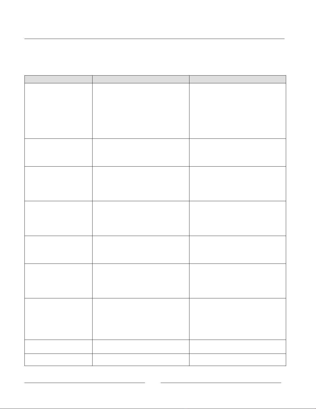
Problem Cause Correction
Poor coating material transfer
efficiency
Workpieces not properly grounded Check the workpiece-to-ground resistance.
Poor coating material formulation Check the coating material.
Booth air flow too high or too low Adjust the air flow.
Power supply or control unit defective Check the power supply output.
Defective high-voltage cable or IPS cable Check the cable resistance or continuity.
Defective charge ring Check the charge ring resistance.
Defective barrel resistor (cable-fed) Check the resistor resistance.
Poor connections Check all of the electrical connections.
Coating material wraps back
on atomizer
Spray booth air velocity too low Increase air flow through the booth.
Vector air pressure too low Increase the vector air pressure.
Poor coating material formulation Check the coating material.
No grounded part in front of atomizer Reprogram the system controls.
Poor coating material
atomization
Turbine speed too low Increase the turbine speed.
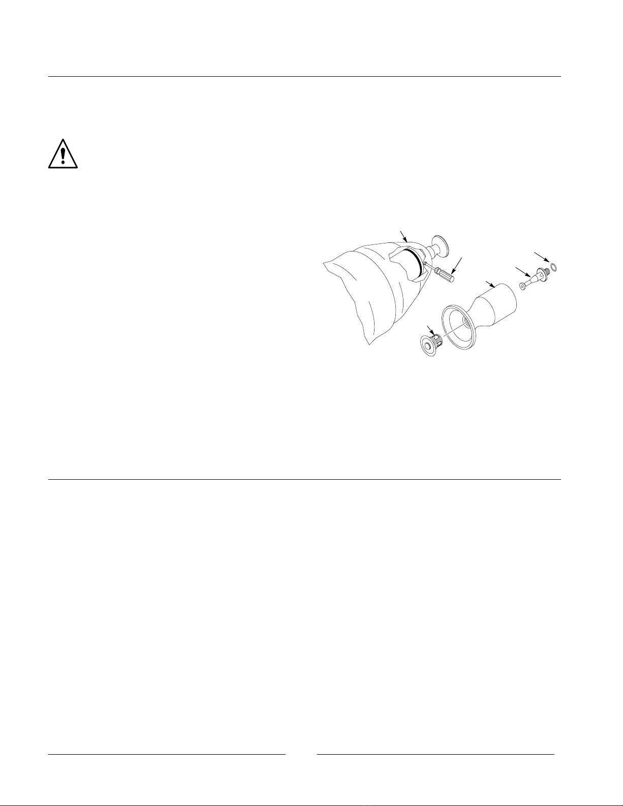
Cup assembly plugged or damaged Clean and inspect the cup assembly.
Coating material viscosity incorrect Change the material viscosity.
Flow rate too high Lower the flow rate.
Coating material not charging Check the electrostatic system.
Turbine will not rotate, rotates
slowly, or oscillates
Turbine or bearing air pressure low Check the turbine and bearing air pressure.
Leaking O-ring in interface plate Remove the turbine and replace the O-ring.
Turbine air regulators not set properly Check the regulator settings.
Turbine air bearings worn or plugged Repair or replace the turbine.
Cup out of balance or damaged Check the cup, and replace it if necessary.
No turbine speed control or
display
Defective transmitter assembly Check the transmitter output.
Defective fiber-optic cable Check the cable output.
Defective fiber-optic module Check the module output.
Defective display or control unit Repair or replace the defective component.
No spray when coating
material turned on
Nozzle or fluid tube plugged Clean or replace the nozzle or fluid tube.
Fluid tubing plugged Check the tubing for blockage.
Valve trigger air pressure low Check the trigger air pressure at valve.
Valve adjusted incorrectly or malfunctioning Repair or replace the valve.
Trigger air switch or solenoid defective Repair or replace the component.
Pattern can not be shaped,
no vector air or pressure low
Vector air tubing kinked or plugged Repair or replace the tubing.
Leaking O-ring in interface plate Remove the turbine and replace the O-ring.
Leak in charge ring or front shroud Replace the O-rings or duckbill seal.
Vector air slots plugged Clean the air slots in the charge ring.
Resistor sleeve installed incorrectly Install the sleeve correctly.
Valve or regulator malfunction Repair or replace the component.
Material keeps flowing when
valve is closed
Valve worn or jammed open Repair or replace the valve.
Switch or solenoid valve defective Repair or replace the component.
Material leaking from valve
weep holes
Valve seals worn Repair or replace the valve.

7
Recommended Cups/Nozzles/Fluid Tubes
Recommended Spare Parts
Cup Assemblies
Part Description Quantity Note
302126 Cup, 2 in. dia, w/fins, insert, assembly 1 A
302127 Cup, 2 in. dia, smooth, insert, assembly 1 A
302130 Cup, 2.5 in. dia, w/fins, insert, assembly 1 A
302131 Cup, 2.5 in. dia, smooth, insert, assembly 1 A
295369 SDistributor, cup 1 A
295368 SSDeflector, distributor 1 A
295390 Distributor, emulsion 1 B
Note A: All cups include a distributor assembly, part 295369.
Note B: Optional distributor, used with emulsions. Replaces distributor assembly, part 295369.
Nozzles
Part Description Quantity Note
295382 Nozzle, fluid, RA-20, 0.020 in. 1 A
295383 Nozzle, fluid, RA-20, 0.030 in. 1 A
295384 Nozzle, fluid, RA-20, 0.040 in. 1 A
295385 Nozzle, fluid, RA-20, 0.050 in. 1 A
295386 Nozzle, fluid, RA-20, 0.060 in. 1 A
295387 Nozzle, fluid, RA-20, 0.070 in. 1 A
295388 Nozzle, fluid, RA-20, 0.080 in. 1 A
940092 O-ring, Viton, black, 0.22 x 0.34 in. 1 A
Note A: All nozzles include an O-ring, part 940092.
Fluid Tubes
Part Description Quantity Note
181761 Tube, fluid, 0.160 in. dia orifice 1
168871 Tube, fluid, 0.100 in. dia orifice 1
Issued 10/2003
Original copyright 1997. Nordson and the Nordson logo are registered trademarks of Nordson Corporation.
Viton is a registered trademark of E.I. DuPont de Nemours & Co.

8
Other manuals for RA-20
2
Table of contents
Other Nordson Electronic Cigarette manuals