TAIFUN GT III User manual

Taifun® GT II /GT II Air–Bedienungsanleitung
deutsch
User Manual
english
GT III
®

english Taifun® GT III –User Manual
2
IMPORTANT
Please read these instructions carefully, before using your
Taifun®GT III rebuildable tank atomizer.
Thank you for purchasing a Taifun® GT III. With this product you
have purchased a high quality rebuildable tank atomizer, which
has been designed exclusively for use with e-liquid. Before use it
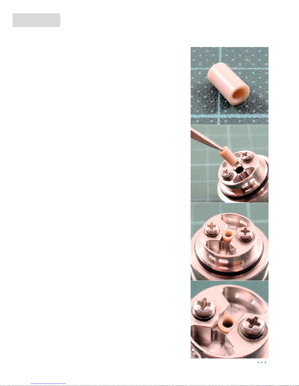
is necessary to install a coil of resistance wire (e.g. NiCr wire)
and a suitable wick (e.g. cotton) according to the instructions of
this manual.
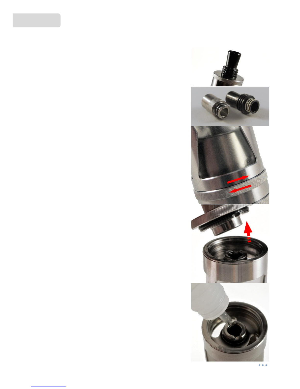
Furthermore, it is required to fill the atomizer with e-liquid after
coil setup. If you are having trouble making a suitable coil, or if
you have no previous experience with rebuildable atomizers,
please contact your supplier or www.smokerstore.de.
After the attachment of a new coil, the resistance should be
measured. To do this, use a multimeter or a suitable battery
device with resistance measurement. If a short circuit is
detected, the atomizer must never be put into operation. Short
circuits can cause damage to the battery device and/or
batteries. In this case, please correct the coil or make a new
coil.

Taifun® GT III –User Manual english
3
IMPORTANT
Please use only liquids which explicitly
are intended for use in e-cigarettes.
The Taifun® GT III is made of high quality materials and has
been thoroughly cleaned prior to delivery. Cleaning before use
is not necessary. Any visible residues are clean water and
glycerine used for pretreatment of o-rings.
If you want to clean the atomizer after longer use, a short rinse
of all parts under warm water is sufficient.
Please thoroughly dry all parts before assembling the atomizer
again. We also recommend that prior to assembly you moisten
the o-rings with a little liquid or glycerine. This increases the
durability of the o-rings and simplifies the assembly.
If an o-ring or an insulator is damaged, please replace it. The
necessary spare parts are partially included in delivery and can
be reordered via your supplier or www.smokerstore.de.

english Taifun® GT III –User Manual
4
Scope of delivery Taifun® GT III
1 x Rebuildable atomizer Taifun® GT III
1 x Info card for authenticity verification
1 x Drip Tip Taifun® GT III
1 x Sealing rings (spare parts)
1 x Giftbox
Specifications
Diameter: 23 mm
Length (without Drip Tip): 52,5 mm
Weight: approx. 82 g
Capacity: approx. 5 ml
Material: Stainless steel (1.4301),
Borosilicate glass,
PTFE (Polytetrafluorethylen)
PA (Polyamid)

Taifun® GT III –User Manual english
5
Attaching a coil
On the base there are 2 screws, which are used to fix the
wire (plus and minus pole).
The screws are slightly offset so that the wire can be easily
attached.
It is advisable to place the wire ends clockwise around the
screws and fix the coil by tightening the screws.
The coil should be located centrally above the air outlet and
should not touch the surrounding metal parts (risk of short
circuit).
The cotton is passed through the coil and into the side
pockets.
The side pockets should be completely covered with cotton
from the inside, but the cotton should not be plugged in.
Via the side openings (depending on the setting of the
Liquid Control) the liquid can get from the tank to the coil.
(see Coil Example, page 18)

english Taifun® GT III –User Manual
6
Liquid Control
The Liquid Control is adjusted by the Drip Tip. The Drip Tip
can be adjusted by 360 °.
The Liquid Control can be easily checked through the glass of
the tank.
Example: Liquid Control maximally opened.
(This picture without tank is only for illustration purposes)
Example: Liquid Control half opened.
(This picture without tank is only for illustration purposes)
Example: Liquid Control closed (for filling).
(This picture without tank is only for illustration purposes)

Taifun® GT III –User Manual english
7
Airflow Control
The adjustment of the airflow is supplied via the AFC ring
located on the underside of the base and has two differently
sized slots. There are eleven air holes under the AFC ring in
total.
While on the one side the holes 1,3,5,7 and 9 are located, the
holes 2,4,6,8,10 and 11 are placed on the opposite side.
Through the slots in the AFC ring you can now alternately
open or close another hole on each side.
You have the option either to adjust the air passage
between one and ten open air holes.
One of the holes is smaller and designed for a very reduced
airflow.

english Taifun® GT III –User Manual
8
Recucing the air channel
Optional available is a conical shaped PEEK tube
(3.35 x 3.55 x 6 mm) with an inside diameter of 2mm.
With this tube a very strong airflow can be achieved,
independent of air flow regulation. It also provides a direct
and stronger airflow direct to the coil, resulting in flavor
intensification.
It is recommended to use tweezers for insertion.
Important: When inserting the tube, make sure that the
narrow end is pushed into the opening first.
The tube should be pushed as completely as possible into
the deck. It should not come into contact with the coil later.

Taifun® GT III –User Manual english
9
Filling the tank
To fill the Taifun® GT III, first close the liquid control. Turn
the drip tip until the liquid control openings are completely
closed.
The liquid flow is now interrupted and you can unscrew the
top cap to fill the tank.
Important: The drip tip should be pulled up a little bit
before loosening the top cap, as otherwise the liquid
control could be adjusted further when loosening the top
cap.
After unscrewing the top cap, the liquid can be filled into
the tank via the side openings.
Important: After filling, the tank should be immediately
closed again with the top cap. The tank should only be
opened as short as necessary.

english Taifun® GT III –User Manual
10
Filling the tank (optional)
Since the supplied drip tip has two "teeth", which are
necessary for adjusting the liquid control, the liquid control
can not be adjusted with other drip tips and thus can not
be closed for filling.
In order to close the liquid control nevertheless for the
duration of the filling process, you have to unscrew the tank
a little. The liquid channels are displaced inside and are also
closed.
Nevertheless, the tank remains tight, as it is still sealed by
the built-in O-ring.
You can now unscrew the top cap as usual.
The tank is filled from above.
Important: After filling, the tank should be immediately
closed again with the top cap. The tank should only be
opened as short as necessary.

Taifun® GT III –User Manual english
11
Filling the tank (optional)
It is also possible to fill from tank from the bottom. To do
this, place the tank upside down and unscrew the base.
The tank must be held upside down during the entire filling
process.
If necessary, the chimney can be pushed aside.
Now, the liquid can be filled into the tank.
Important: When screwing in, you must pay attention to
keep the tank upside down.

english Taifun® GT III –User Manual
12
Adjusting the positive pole
The positive pole of the 510 connection can be adjusted to
match the pole of the used device/mod.
This requires a suitable screwdriver.
The positive pole should only be screwed out as far as
necessary.

Taifun® GT III –User Manual english
13
Taifun® GT III parts
1spring
2countersunk head screw
3positive pole base plate
4positive pole screw
5positive pole mount
6isolator (PA)
73x spacer (PA)
8O-ring 5x1,5 mm (NBR 50)
9positive pole isolator (PEEK)
10 negative pole screw
11 negative pole mount
12 AFC ring
13 base
14 O-ring 17x1 mm (NBR 50
15 O-ring 15x1 mm (NBR 50)
16 deck
17 O-ring 20x1 mm (NBR 40)
18 tank cover
19 glass tank
20 tank ring
21 O-ring 19x1 mm (NBR 70)
22 chamber/chimney
23 2x O-ring 5x1,5 mm (NBR 50)
24 top cap
25 O-ring 15x1 mm (NBR 50)
26 drip tip
27 2x O-ring 5x1,5 mm (NBR 50)
IMPORTANT
It is recommended to moisten the O-rings a little with liquid during assembly.
This allows the individual parts to be screwed together much easily.

english Taifun® GT III –User Manual
14
Taifun® GT III assembly
1spring
2countersunk head screw
3positive pole base plate
4positive pole screw
5positive pole mount
6isolator (PA)
73x spacer
8O-ring 5x1,5 mm
Pic 1: The isolator [6] is pushed over the
positive pole base plate [3].
Pic 2: The isolator [6] must be fully seated
on the positive pole base plate [3].
Pic 3: On the other side, the three spacers
[7] are attached.
Pic 4: The O-ring [8] is also pushed over
the isolator [6].
Pic 5: Push the O-ring [8] as far as possible
onto the insulator [6].
Pic 6: Then insert the positive-pole screw [4]
into the positive-pole holder [5].
Pic 7: Screw the screw [4] as far as it will go.
Pic 8: The screw [4] is now screwed into
the positive pole base plate [3].
Pic 9: The countersunk screw [2] is now
pushed into the spring [1].
Pic 10:Push the spring [1] as far as possible
onto the screw [2].
Pic 11:Put the screw [2] into the positive-
pole base [3] at the bottom.
Pic 12:Carefully screw in until it stops.

Taifun® GT III –User Manual english
15
Taifun® GT III assembly
Pic 13:The parts 9, 10, 11 as well as 15 and
16 are now required.
Pic 14:First, put the O-ring [15] in the
recess on the deck [16].
Pic 15:The O-ring [15] must be positioned
exactly at the intended location on the deck
[16].
Pic 16:Now insert the positive pole
insulator [9] into the hole provided in the
deck [16].
Pic 17:It is important to insert the insulator
[9] carefully, evenly and, if necessary, with
slight turning movements.
Pic 18:The isolator [9] must be fully seated
in the deck [16].
Pic 19:The negative pole screw [10] is
inserted through the negative pole holder
[11] …
Pic 20: …and then screwed to the deck
[16].
Pic 21:When the screw [10] is correctly
seated, only the screw head looks out of the
deck [16].
Pic 22: The positive pole base [3] is inserted
from below into the deck [16]. The spacers
are then positioned exactly in the recesses.
Pic 23:The positive pole [4] is now at the
same level as the negative pole [10].
Pic 24: The O-ring [14] is now installed on
the base [13].
Pic 25:The O-ring [14] should sit flush in
the recess of the base [13].
Pic 26: The AFC ring [12] is placed on the
base [13] and held there by the O-ring
[14].
Pic 27: The AFC ring [12] can now be
moved laterally on the base [13].
Pic 28: The deck [16] can now be inserted
into the base [13].

english Taifun® GT III –User Manual
16
Taifun® GT III assembly
Pic 29:
The deck [16] and the base [13] are now
screwed together.
Pic 30:Now the base should look like this.
Pic 31:The two O-rings [23] are installed in
the recesses at the upper end of the
chimney [22].
Pic 32:The O-rings [23] should now be
seated, as on this pic..
Pic 33:The O-ring [21] is now attached to
the tank ring [20].
Pic 34:For this purpose there is a fine edge
on the tank ring [20] in which the O-ring
[21] should be seated.
Pic 35:The O-ring [17] is now inserted into
the tank cover [18].
Pic 36:The O-ring [17] is located in a small
groove in the tank cover [18].
Pic 37:The glass tank [19] is now pushed
into the tank cover [18].
Pic 38:The glass tank [19] sits on the O-ring
[17] in the tank cover [18]. Check the
correct seat again if necessary.
Pic 39:The tank ring [20] is now placed on
the tank cover [18] …
Pic 40:... and screwed on there. If
necessary, use pointed pliers to grasp the
filling openings.
Pic 41:The tank ring [20] should now sit
correctly on the tank cover [18].
Pic 42:Now insert the chimney [22] into
the tank ring [20] through the tank cover
[18].
IMPORTANT: The O-rings on the chimney
should be moistened with some liquid
before this step.
Pic 43:The chimney [22] should now be
inserted into the tank [18].
Pic 44:On the top you can see the
chinmey [22] sitting in the tank ring [20].

Taifun® GT III –User Manual english
17
Taifun® GT III assembly
Pic 45:Attach the O-ring [25] on the top cap
[24].
Pic 46:In the top cap [24] there is a
corresponding recess for the O-ring [25].
Pic 46:The top cap [24] can now be
screwed onto the tank ring [20].
Pic 47:Top cap [24], tank ring [20] and tank
cover [18] should be flush with each other.
Pic 48:The O-rings [27] are mounted on the
drip tip [26].
Pic 49:Notice the two "teeth" at the lower
edge of the drip tip [26].
Pic 50:The drip tip [26] is placed on the top
cap [24] so that it "engages" exactly in the
chimney.
Pic 51:The drip tip [26] now sits flush on
the top cap [24]. The liquid control can be
operated with rotary movements.
Pic 52:The tank [18] is now crewed onto
the base [16].
Pic 53:Both parts are now screwed
together.
Pic 54:Done!

english Taifun® GT III –User Manual
18
Coil example
The two screws are loosened slightly,
in order to fix the wire.
The wire is placed behind the winding
aid.
Now guide the wire from bottom to
top around the winding aid.
Repeat this until you have the desired
number of turns.
Now you can fold the ends of the
wire a little. This makes the coil
easier to attach.
The wire is placed around the screws
...
... and then clockwise around the
screws.
Use a suitable screwdriver to tighten
the screws. The rotary movement
during clamping, also tightens the
wire.
The same is done with the second
screw. The winding aid should be
held so that the coil does not move.
Now you can adjust the coil a bit, if
necessary.
Carefully remove the winding aid.
Cut the wire ends flush with the screw
heads.

Taifun® GT III –User Manual english
19
Coil example
Viewed from above, the winding
should now be uniformly and
centrally aligned, covering the air
hole.
Now a broad strand cotton is needed.
The cotton is tipped on one side and
passed through the coil.
The cotton can then be shortened. On
each side should be about 8-10 mm
cotton.
One end of the cotton is now
carefully guided into the side
pockets.
On the other side, too.
The cotton should fill the pockets
completely, but it must not be
stuffed. The cotton wool must be
distributed loosely and airily.
It is important that there is some
cotton behind each liquid opening.
IMPORTANT
After applying a coil, the cotton must be pre-moistened with liquid
before the atomizer is screwed together and the tank is filled.
The winding shown here is only an example. Other wires, a different number of turns, and larger /
smaller diameters are also possible.

english Taifun® GT III –User Manual
20
SMOKERSTORE
ELECTRONIC VAPING PRODUCTS
SmokerStore GmbH
www.smokerstore.de
Table of contents
Other TAIFUN Electronic Cigarette manuals